Page 3045 of 5267
INSTALLATION
1. Install the input speed sensor (1) into the transmis-
sion case.
NOTE: Before installing the speed sensor bolt, it
will be necessary to replenish the sealing patch on
the bolt using MOPAR
Lock & Seal Adhesive.
2. Install the bolt to hold the input speed sensor into
the transmission case. Tighten the bolt to 9 Nꞏm
(80 in.lbs.).
3. Install the wiring connector onto the input speed
sensor
4. Verify the transmission fluid level. Add fluid as nec-
essary.
5. Lower vehicle.
Page 3051 of 5267

SENSOR-OUTPUT SPEED
DESCRIPTION
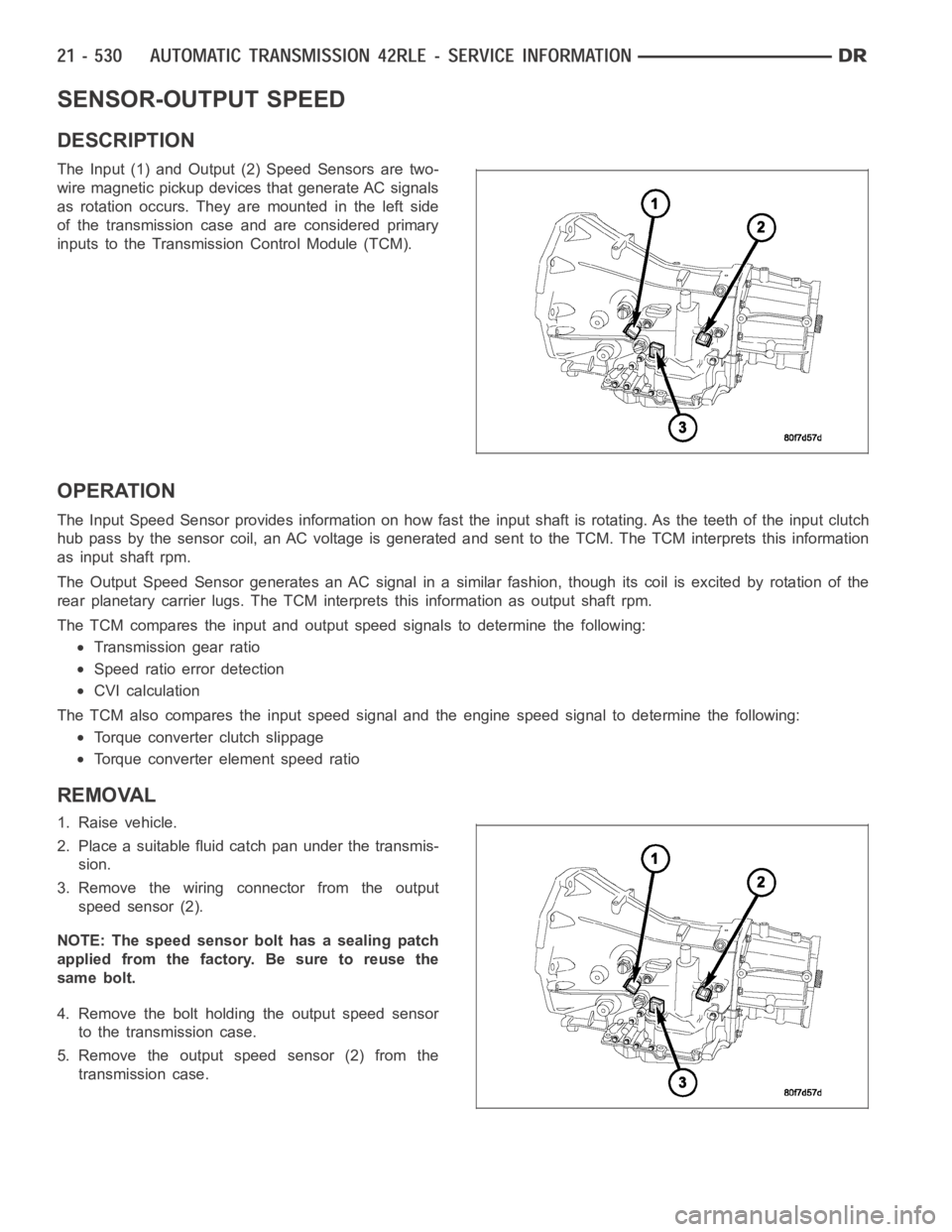
The Input (1) and Output (2) Speed Sensors are two-
wire magnetic pickup devices that generate AC signals
as rotation occurs. They are mounted in the left side
of the transmission case and are considered primary
inputs to the Transmission Control Module (TCM).
OPERATION
The Input Speed Sensor provides information on how fast the input shaft is rotating. As the teeth of the input clutch
hub pass by the sensor coil, an AC voltage is generated and sent to the TCM. The TCM interprets this information
as input shaft rpm.
The Output Speed Sensor generates an AC signal in a similar fashion, thoughitscoilisexcitedbyrotationofthe
rear planetary carrier lugs. The TCM interprets this information as outputshaftrpm.
The TCM compares the input and output speed signals to determine the following:
Transmission gear ratio
Speed ratio error detection
CVI calculation
The TCM also compares the input speed signal and the engine speed signal to determine the following:
Torque converter clutch slippage
Torque converter element speed ratio
REMOVAL
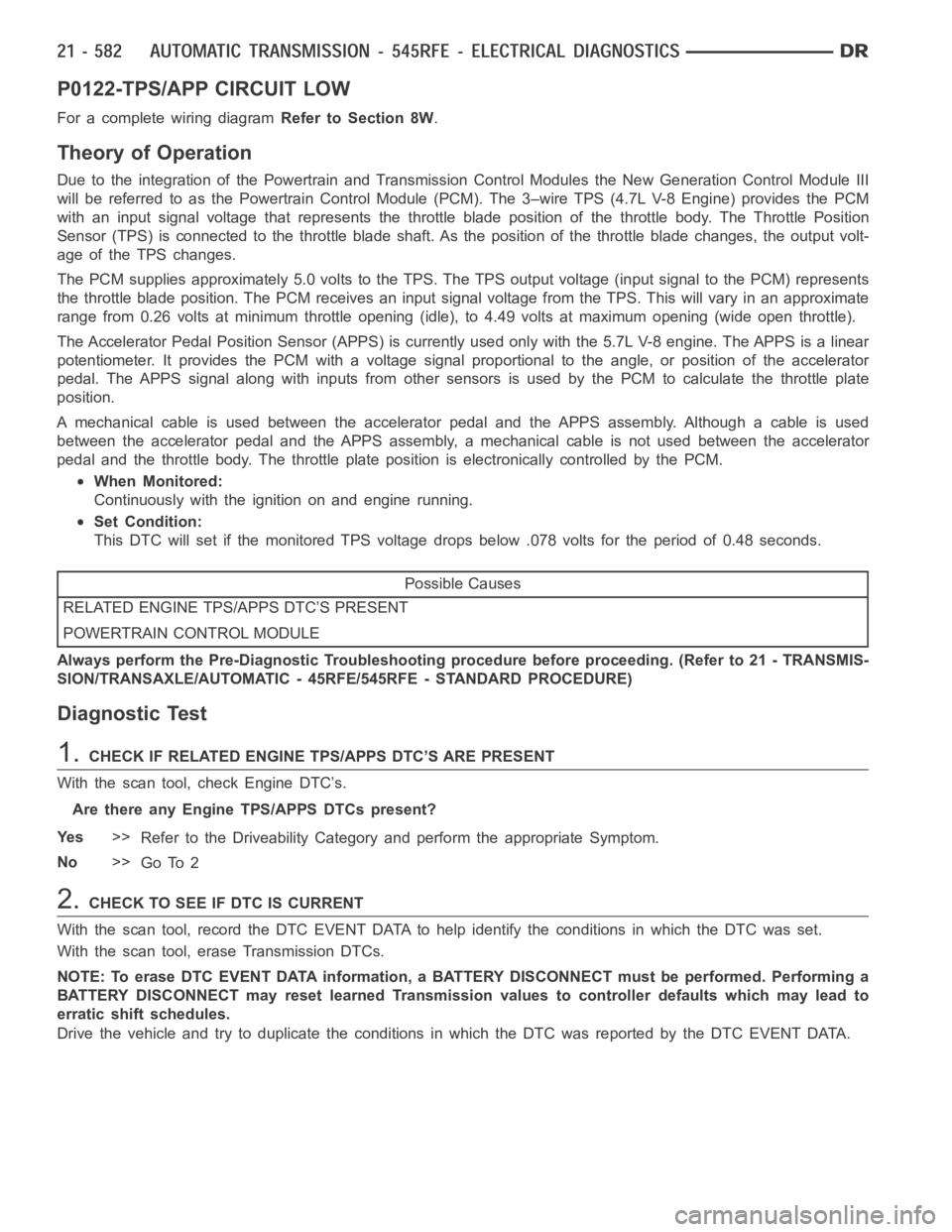
1. Raise vehicle.
2. Place a suitable fluid catch pan under the transmis-
sion.
3. Remove the wiring connector from the output
speed sensor (2).
NOTE: The speed sensor bolt has a sealing patch
applied from the factory. Be sure to reuse the
same bolt.
4. Remove the bolt holding the output speed sensor
to the transmission case.
5. Remove the output speed sensor (2) from the
transmission case.
Page 3052 of 5267
INSTALLATION
1. Install the output speed sensor (2) into the trans-
mission case.
NOTE: Before installing the speed sensor bolt, it
will be necessary to replenish the sealing patch on
the bolt using MOPAR
Lock & Seal Adhesive.
2. Install the bolt to hold the output speed sensor into
the transmission case. Tighten the bolt to 9 Nꞏm
(80 in.lbs.).
3. Install the wiring connector onto the output speed
sensor
4. Verify the transmission fluid level. Add fluid as nec-
essary.
5. Lower vehicle.
Page 3084 of 5267
1. Disconnect the transmission range sensor (5) and
solenoid/pressure switchassembly wiring connec-
tors.
2. Disconnect the variable line pressure connector (4),
if equipped.
3. Disconnect the shift cable from the shift lever (at
the transmission).
4. Move the manual shift lever clockwise as far as it
will go. This should be one position past the L posi-
tion. Then remove the manual shift lever.
NOTE: One of the oil pan bolts has a sealing patch
applied from the factory. Separate this bolts for
reuse.
5. Remove transmission pan bolts (2).
6. Remove transmission oil pan (1).
Page 3103 of 5267

P0122-TPS/APP CIRCUIT LOW
For a complete wiring diagramRefer to Section 8W.
Theory of Operation
Due to the integration of the Powertrain and Transmission Control Modulesthe New Generation Control Module III
will be referred to as the Powertrain Control Module (PCM). The 3–wire TPS (4.7L V-8 Engine) provides the PCM
with an input signal voltage that represents the throttle blade position of the throttle body. The Throttle Position
Sensor (TPS) is connected to the throttle blade shaft. As the position of the throttle blade changes, the output volt-
age of the TPS changes.
The PCM supplies approximately 5.0 volts to the TPS. The TPS output voltage(input signal to the PCM) represents
the throttle blade position. The PCM receives an input signal voltage fromthe TPS. This will vary in an approximate
range from 0.26 volts at minimum throttle opening (idle), to 4.49 volts at maximum opening (wide open throttle).
The Accelerator Pedal Position Sensor (APPS) is currently used only with the 5.7L V-8 engine. The APPS is a linear
potentiometer. It provides the PCM with a voltage signal proportional to the angle, or position of the accelerator
pedal. The APPS signal along with inputs from other sensors is used by the PCM to calculate the throttle plate
position.
A mechanical cable is used between the accelerator pedal and the APPS assembly. Although a cable is used
between the accelerator pedal and the APPS assembly, a mechanical cable isnot used between the accelerator
pedal and the throttle body. The throttle plate position is electronically controlled by the PCM.
When Monitored:
Continuously with the ignition on and engine running.
Set Condition:
This DTC will set if the monitored TPS voltage drops below .078 volts for theperiod of 0.48 seconds.
Possible Causes
RELATED ENGINE TPS/APPS DTC’S PRESENT
POWERTRAIN CONTROL MODULE
Always perform the Pre-Diagnostic Troubleshooting procedure before proceeding. (Refer to 21 - TRANSMIS-
SION/TRANSAXLE/AUTOMATIC - 45RFE/545RFE - STANDARD PROCEDURE)
Diagnostic Test
1.CHECK IF RELATED ENGINE TPS/APPS DTC’S ARE PRESENT
With the scan tool, check Engine DTC’s.
Are there any Engine TPS/APPS DTCs present?
Ye s>>
Refer to the Driveability Category and perform the appropriate Symptom.
No>>
Go To 2
2.CHECK TO SEE IF DTC IS CURRENT
With the scan tool, record the DTC EVENT DATA to help identify the conditionsinwhichtheDTCwasset.
With the scan tool, erase Transmission DTCs.
NOTE: To erase DTC EVENT DATA information, a BATTERY DISCONNECT must be performed. Performing a
BATTERY DISCONNECT may reset learned Transmission values to controller defaults which may lead to
erratic shift schedules.
Drive the vehicle and try to duplicate the conditions in which the DTC was reported by the DTC EVENT DATA.
Page 3104 of 5267

With the scan tool, read Transmission DTCs.
Did the DTC P0122 TPS/APPS LOW, reset?
Ye s>>
Using the schematics as a guide, check the Powertrain Control Module (PCM)terminals for corrosion,
damage, or terminal push out. Pay particular attention to all power and ground circuits. If no problems
are found, replace the PCM per the Service Information. With the scan tool,perform QUICK LEARN.
Perform 45RFE/545RFE TRANSMISSION VERIFICATION TEST - VER 1. (Refer to 21- TRANSMIS-
SION/TRANSAXLE/AUTOMATIC - 45RFE/545RFE - STANDARD PROCEDURE)
No>>
Go To 3
3.INTERMITTENT WIRING AND CONNECTORS
The conditions necessary to set the DTC are not present at this time.
Using the schematics as a guide, inspect the wiring and connectors specifictothiscircuit.
Wiggle the wiring and connectors while checking for shorted and open circuits.
With the scan tool, check the DTC EVENT DATA to help identify the conditionsin which the DTC was set.
Were there any problems found?
Ye s>>
Repair as necessary.
Perform 45RFE/545RFE TRANSMISSION VERIFICATION TEST - VER 1. (Refer to 21- TRANSMIS-
SION/TRANSAXLE/AUTOMATIC - 45RFE/545RFE - STANDARD PROCEDURE)
No>>
Te s t C o m p l e t e .
Page 3105 of 5267

P0123-TPS/APP CIRCUIT HIGH
For a complete wiring diagramRefer to Section 8W.
Theory of Operation
Due to the integration of the Powertrain and Transmission Control Modulesthe New Generation Control Module III
will be referred as the Powertrain Control Module (PCM). The 4.7L V-8 Throttle Positioning Sensor (TPS) provides
the PCM with an input signal voltage that represents the throttle blade position of the throttle body. The TPS is
connected to the throttle blade shaft. As the position of the throttle blade changes, the output voltage of the TPS
changes.
The 5.7L V-8 Accelerator Pedal Position Sensor (APPS) is a linear potentiometer that provides the PCM with a
voltage signal proportional to the angle, or position of the accelerator pedal. The APPS signal along with inputs from
other sensors is used by the PCM to calculate the throttle plate position which is electronically controlled.
When Monitored:
Continuously with the ignition on and engine running.
Set Condition:
This DTC will set if the monitored TPS voltage rises above 4.94 volts for theperiod of 0.48 seconds.
Possible Causes
RELATED ENGINE TPS/APPS DTC’S PRESENT
POWERTRAIN CONTROL MODULE
Always perform the Pre-Diagnostic Troubleshooting procedure before proceeding. (Refer to 21 - TRANSMIS-
SION/TRANSAXLE/AUTOMATIC - 45RFE/545RFE - STANDARD PROCEDURE)
Diagnostic Test
1.DETERMINING IF RELATED ENGINE TPS/APPS DTCS ARE PRESENT
With the scan tool, check Engine DTCs, this includes all one trip failures.
Are there any Engine TPS/APPS DTCs present?
Ye s>>
Refer to the Driveability category and perform the appropriate symptom.
No>>
Go To 2
2.CHECK IF THE DTC IS CURRENT
With the scan tool, record the DTC EVENT DATA to help identify the conditionsinwhichtheDTCwasset.
With the scan tool, erase Transmission DTCs.
NOTE: To erase DTC EVENT DATA information, a BATTERY DISCONNECT must be performed. Performing a
BATTERY DISCONNECT may reset all learned Transmission values to controller defaults that could lead to
an inconsistent shift schedule.
Drive the vehicle and try to duplicate the conditions in which the DTC was reported by the DTC EVENT DATA.
With the scan tool, read Transmission DTCs.
Did the DTC P0123 TPS/APPS HIGH, reset?
Ye s>>
Using the schematics as a guide, check the Powertrain Control Module (PCM)terminals for corrosion,
damage, or terminal push out. Pay particular attention to all power and ground circuits. If no problems
are found, replace the PCM per the Service Information. With the scan tool,perform QUICK LEARN.
Perform 45RFE/545RFE TRANSMISSION VERIFICATION TEST - VER 1. (Refer to 21- TRANSMIS-
SION/TRANSAXLE/AUTOMATIC - 45RFE/545RFE - STANDARD PROCEDURE)
No>>
Go To 3
Page 3106 of 5267
3.INTERMITTENT WIRING AND CONNECTORS
The conditions necessary to set the DTC are not present at this time.
Using the schematics as a guide, inspect the wiring and connectors specifictothiscircuit.
Wiggle the wiring and connectors while checking for shorted and open circuits.
With the scan tool, check the DTC EVENT DATA to help identify the conditionsin which the DTC was set.
Were there any problems found?
Ye s>>
Repair as necessary.
Perform 45RFE/545RFE TRANSMISSION VERIFICATION TEST - VER 1. (Refer to 21- TRANSMIS-
SION/TRANSAXLE/AUTOMATIC - 45RFE/545RFE - STANDARD PROCEDURE)
No>>
Te s t C o m p l e t e .