2006 DODGE RAM SRT-10 service
[x] Cancel search: servicePage 3183 of 5267
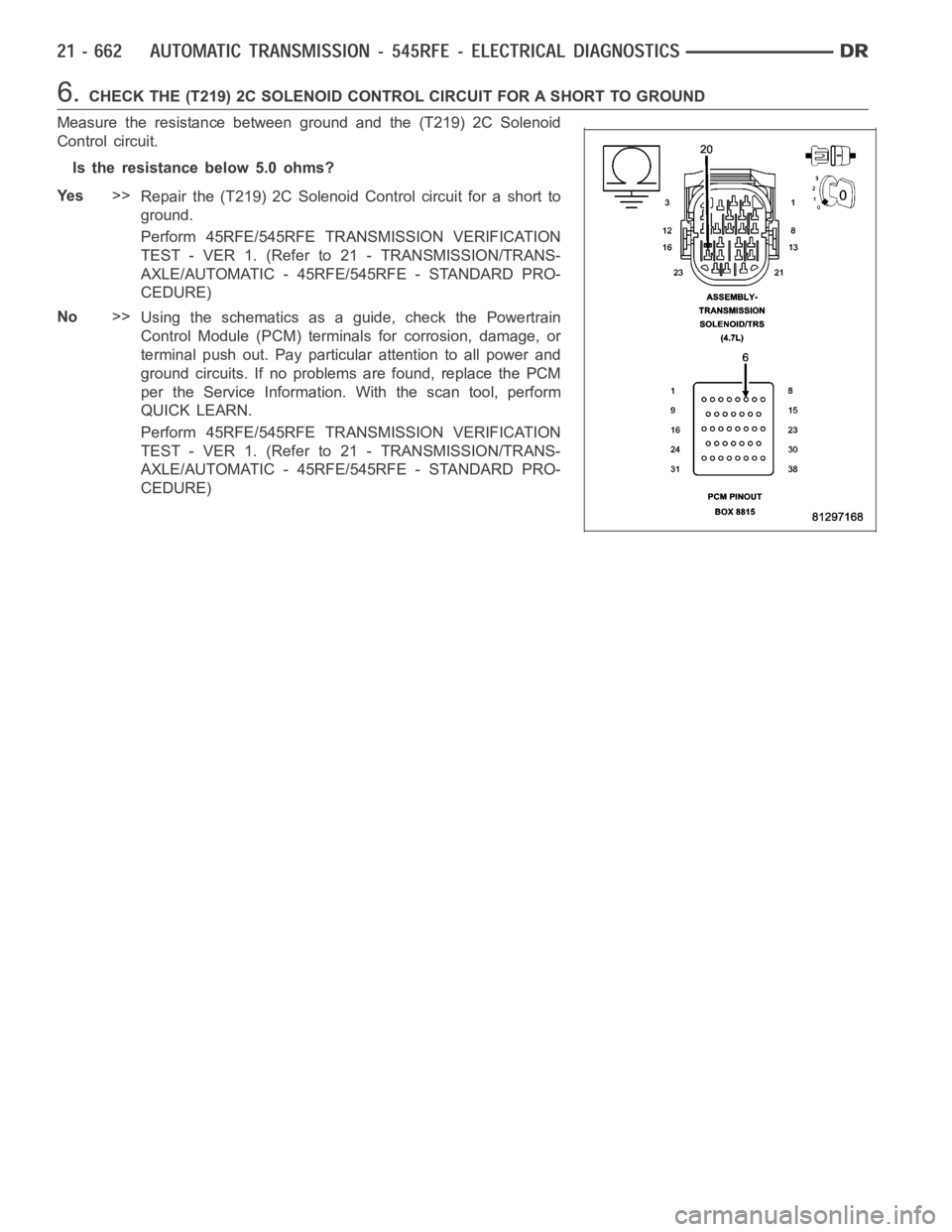
6.CHECK THE (T219) 2C SOLENOID CONTROL CIRCUIT FOR A SHORT TO GROUND
Measure the resistance between ground and the (T219) 2C Solenoid
Control circuit.
Is the resistance below 5.0 ohms?
Ye s>>
Repair the (T219) 2C Solenoid Control circuit for a short to
ground.
Perform 45RFE/545RFE TRANSMISSION VERIFICATION
TEST - VER 1. (Refer to 21 - TRANSMISSION/TRANS-
AXLE/AUTOMATIC - 45RFE/545RFE - STANDARD PRO-
CEDURE)
No>>
Using the schematics as a guide, check the Powertrain
Control Module (PCM) terminals for corrosion, damage, or
terminal push out. Pay particular attention to all power and
ground circuits. If no problems are found, replace the PCM
per the Service Information.With the scan tool, perform
QUICK LEARN.
Perform 45RFE/545RFE TRANSMISSION VERIFICATION
TEST - VER 1. (Refer to 21 - TRANSMISSION/TRANS-
AXLE/AUTOMATIC - 45RFE/545RFE - STANDARD PRO-
CEDURE)
Page 3186 of 5267
Monitor the OD Solenoid LED on the Transmission Simulator.
Did the OD Solenoid LED on the Transmission Simulator blink on and off?
Ye s>>
Go To 3
No>>
Go To 4
3.CHECK THE TRANSMISSION SOLENOID/TRS ASSEMBLY
With the scan tool, continue to actuate the OD Solenoid for the period of 2 minutes with the Transmission Simulator
still connected.
After 2 minutes of actuation, with the scan tool, stop the actuation and check for transmission DTCs.
Did the DTC P0760 reset during the actuation test?
Ye s>>
Go To 4
No>>
Replace the Transmission Solenoid/TRS Assembly per the Service Information. (Refer to 21 - TRANS-
MISSION/TRANSAXLE/AUTOMATIC - 45RFE/545RFE/TRANS SOLENOID/TRS ASSY -REMOVAL)
Perform 45RFE/545RFE TRANSMISSION VERIFICATION TEST - VER 1. (Refer to 21- TRANSMIS-
SION/TRANSAXLE/AUTOMATIC - 45RFE/545RFE - STANDARD PROCEDURE)
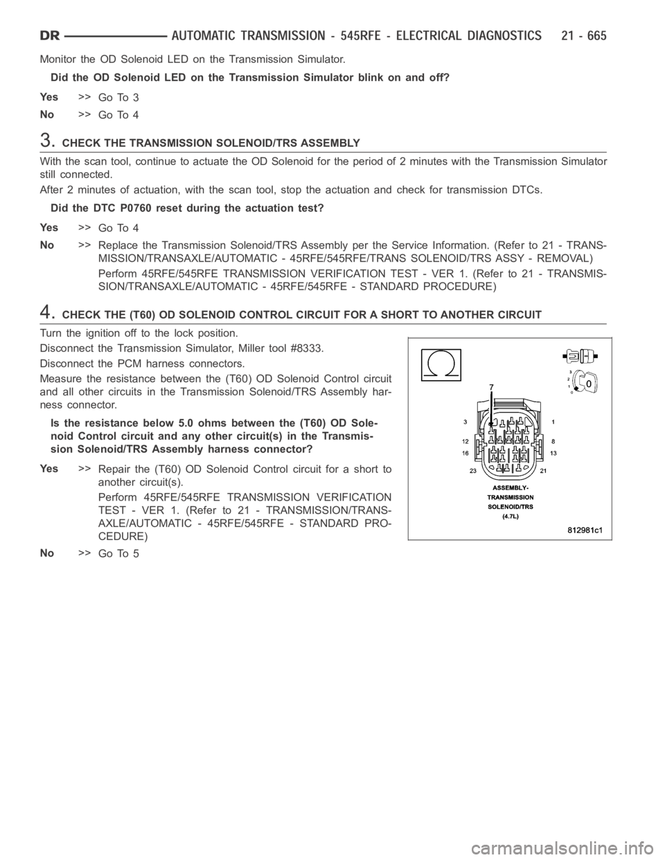
4.CHECK THE (T60) OD SOLENOID CONTROL CIRCUIT FOR A SHORT TO ANOTHER CIRCUIT
Turn the ignition off to the lock position.
Disconnect the Transmission Simulator, Miller tool #8333.
Disconnect the PCM harness connectors.
Measure the resistance between the (T60) OD Solenoid Control circuit
and all other circuits in the Transmission Solenoid/TRS Assembly har-
ness connector.
Is the resistance below 5.0 ohms between the (T60) OD Sole-
noid Control circuit and any other circuit(s) in the Transmis-
sion Solenoid/TRS Assembly harness connector?
Ye s>>
Repair the (T60) OD Solenoid Control circuit for a short to
another circuit(s).
Perform 45RFE/545RFE TRANSMISSION VERIFICATION
TEST - VER 1. (Refer to 21 - TRANSMISSION/TRANS-
AXLE/AUTOMATIC - 45RFE/545RFE - STANDARD PRO-
CEDURE)
No>>
Go To 5
Page 3187 of 5267
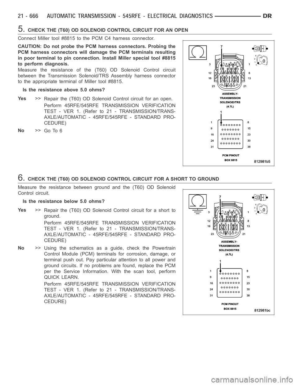
5.CHECK THE (T60) OD SOLENOID CONTROL CIRCUIT FOR AN OPEN
Connect Miller tool #8815 to the PCM C4 harness connector.
CAUTION: Do not probe the PCM harness connectors. Probing the
PCM harness connectors will damage the PCM terminals resulting
in poor terminal to pin connection. Install Miller special tool #8815
to perform diagnosis.
Measure the resistance of the (T60) OD Solenoid Control circuit
between the Transmission Solenoid/TRS Assembly harness connector
to the appropriate terminal of Miller tool #8815.
Is the resistance above 5.0 ohms?
Ye s>>
Repair the (T60) OD SolenoidControl circuit for an open.
Perform 45RFE/545RFE TRANSMISSION VERIFICATION
TEST - VER 1. (Refer to 21 - TRANSMISSION/TRANS-
AXLE/AUTOMATIC - 45RFE/545RFE - STANDARD PRO-
CEDURE)
No>>
Go To 6
6.CHECK THE (T60) OD SOLENOID CONTROL CIRCUIT FOR A SHORT TO GROUND
Measure the resistance between ground and the (T60) OD Solenoid
Control circuit.
Is the resistance below 5.0 ohms?
Ye s>>
Repair the (T60) OD Solenoid Control circuit for a short to
ground.
Perform 45RFE/545RFE TRANSMISSION VERIFICATION
TEST - VER 1. (Refer to 21 - TRANSMISSION/TRANS-
AXLE/AUTOMATIC - 45RFE/545RFE - STANDARD PRO-
CEDURE)
No>>
Using the schematics as a guide, check the Powertrain
Control Module (PCM) terminals for corrosion, damage, or
terminal push out. Pay particular attention to all power and
ground circuits. If no problems are found, replace the PCM
per the Service Information.With the scan tool, perform
QUICK LEARN.
Perform 45RFE/545RFE TRANSMISSION VERIFICATION
TEST - VER 1. (Refer to 21 - TRANSMISSION/TRANS-
AXLE/AUTOMATIC - 45RFE/545RFE - STANDARD PRO-
CEDURE)
Page 3190 of 5267
Monitor the UD Solenoid LED on the Transmission Simulator.
Did the UD Solenoid LED on the Transmission Simulator blink on and off?
Ye s>>
Go To 3
No>>
Go To 4
3.CHECK THE TRANSMISSION SOLENOID/TRS ASSEMBLY
With the scan tool, continue to actuatethe UD Solenoid for the period of 2 minutes with the Transmission Simulator
still connected.
After 2 minutes of actuation, with the scan tool, stop the actuation and check for transmission DTCs.
Did the DTC P0765 reset during the actuation test?
Ye s>>
Go To 4
No>>
Replace the Transmission Solenoid/TRS Assembly per the Service Information. (Refer to 21 - TRANS-
MISSION/TRANSAXLE/AUTOMATIC - 45RFE/545RFE/TRANS SOLENOID/TRS ASSY -REMOVAL)
Perform 45RFE/545RFE TRANSMISSION VERIFICATION TEST - VER 1. (Refer to 21- TRANSMIS-
SION/TRANSAXLE/AUTOMATIC - 45RFE/545RFE - STANDARD PROCEDURE)
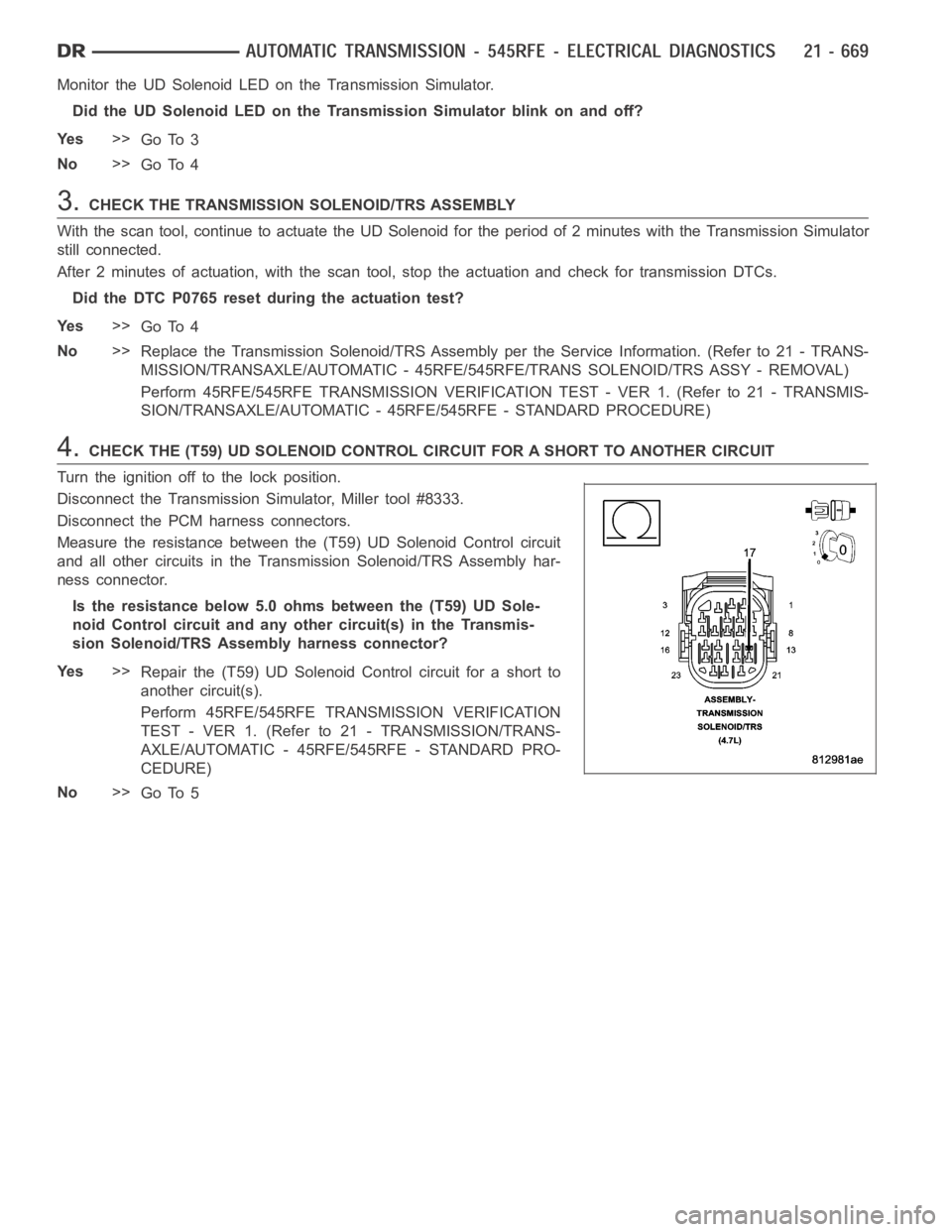
4.CHECK THE (T59) UD SOLENOID CONTROL CIRCUIT FOR A SHORT TO ANOTHER CIRCUIT
Turn the ignition off to the lock position.
Disconnect the Transmission Simulator, Miller tool #8333.
Disconnect the PCM harness connectors.
Measure the resistance between the (T59) UD Solenoid Control circuit
and all other circuits in the Transmission Solenoid/TRS Assembly har-
ness connector.
Is the resistance below 5.0 ohms between the (T59) UD Sole-
noid Control circuit and any other circuit(s) in the Transmis-
sion Solenoid/TRS Assembly harness connector?
Ye s>>
Repair the (T59) UD Solenoid Control circuit for a short to
another circuit(s).
Perform 45RFE/545RFE TRANSMISSION VERIFICATION
TEST - VER 1. (Refer to 21 - TRANSMISSION/TRANS-
AXLE/AUTOMATIC - 45RFE/545RFE - STANDARD PRO-
CEDURE)
No>>
Go To 5
Page 3191 of 5267
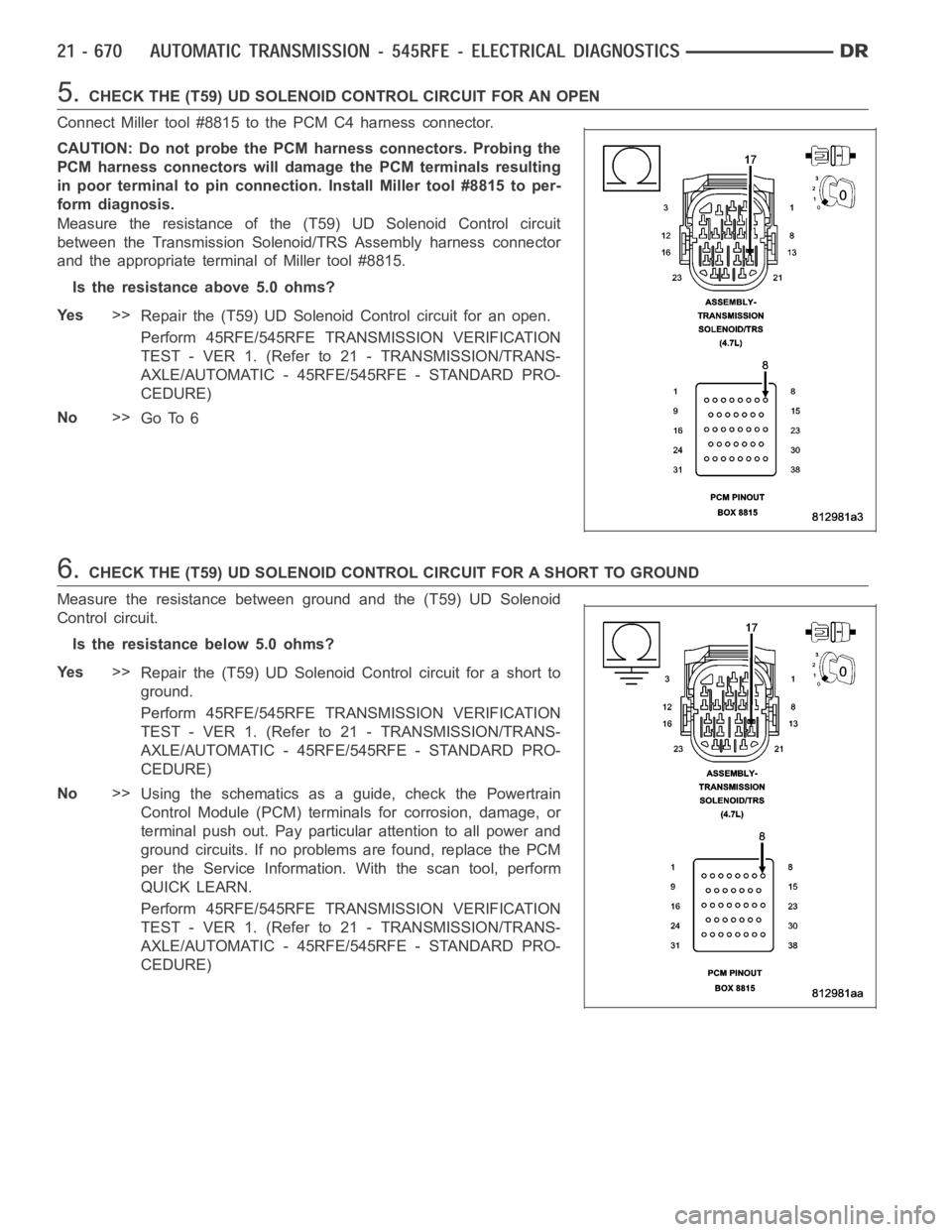
5.CHECK THE (T59) UD SOLENOID CONTROL CIRCUIT FOR AN OPEN
Connect Miller tool #8815 to the PCM C4 harness connector.
CAUTION: Do not probe the PCM harness connectors. Probing the
PCM harness connectors will damage the PCM terminals resulting
in poor terminal to pin connection. Install Miller tool #8815 to per-
form diagnosis.
Measure the resistance of the (T59) UD Solenoid Control circuit
between the Transmission Solenoid/TRS Assembly harness connector
and the appropriate terminal of Miller tool #8815.
Is the resistance above 5.0 ohms?
Ye s>>
Repair the (T59) UD Solenoid Control circuit for an open.
Perform 45RFE/545RFE TRANSMISSION VERIFICATION
TEST - VER 1. (Refer to 21 - TRANSMISSION/TRANS-
AXLE/AUTOMATIC - 45RFE/545RFE - STANDARD PRO-
CEDURE)
No>>
Go To 6
6.CHECK THE (T59) UD SOLENOID CONTROL CIRCUIT FOR A SHORT TO GROUND
Measure the resistance between ground and the (T59) UD Solenoid
Control circuit.
Is the resistance below 5.0 ohms?
Ye s>>
Repair the (T59) UD Solenoid Control circuit for a short to
ground.
Perform 45RFE/545RFE TRANSMISSION VERIFICATION
TEST - VER 1. (Refer to 21 - TRANSMISSION/TRANS-
AXLE/AUTOMATIC - 45RFE/545RFE - STANDARD PRO-
CEDURE)
No>>
Using the schematics as a guide, check the Powertrain
Control Module (PCM) terminals for corrosion, damage, or
terminal push out. Pay particular attention to all power and
ground circuits. If no problems are found, replace the PCM
per the Service Information.With the scan tool, perform
QUICK LEARN.
Perform 45RFE/545RFE TRANSMISSION VERIFICATION
TEST - VER 1. (Refer to 21 - TRANSMISSION/TRANS-
AXLE/AUTOMATIC - 45RFE/545RFE - STANDARD PRO-
CEDURE)
Page 3194 of 5267
Monitor the 4C Solenoid LED on the Transmission Simulator.
Did the 4C Solenoid LED on the Transmission Simulator blink on and off?
Ye s>>
Go To 3
No>>
Go To 4
3.CHECK THE TRANSMISSION SOLENOID/TRS ASSEMBLY
With the scan tool, continue to actuate the 4C Solenoid for the period of 2 minutes with the Transmission Simulator
still connected.
After 2 minutes of actuation, with the scan tool, stop the actuation and check for transmission DTCs.
Did the DTC P0770 reset during the actuation test?
Ye s>>
Go To 4
No>>
Replace the Transmission Solenoid/TRS Assembly per the Service Information. (Refer to 21 - TRANS-
MISSION/TRANSAXLE/AUTOMATIC - 45RFE/545RFE/TRANS SOLENOID/TRS ASSY -REMOVAL)
Perform 45RFE/545RFE TRANSMISSION VERIFICATION TEST - VER 1. (Refer to 21- TRANSMIS-
SION/TRANSAXLE/AUTOMATIC - 45RFE/545RFE - STANDARD PROCEDURE)
4.CHECK THE (T259) 4C SOLENOID CONTROL CIRCUIT FOR A SHORT TO ANOTHER CIRCUIT
Turn the ignition off to the lock position.
Disconnect the Transmission Simulator, Miller tool #8333.
Disconnect the PCM harness connectors.
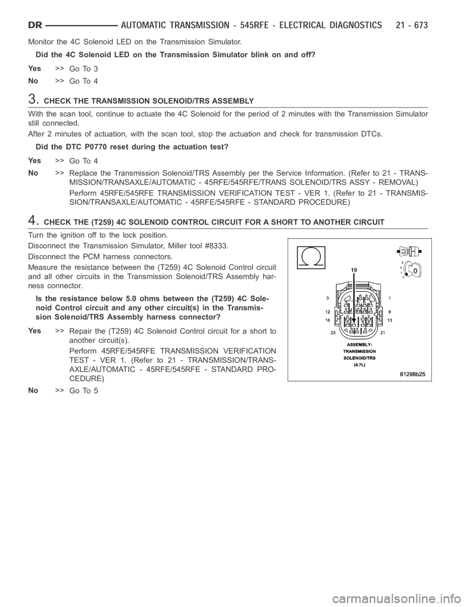
Measure the resistance between the (T259) 4C Solenoid Control circuit
and all other circuits in the Transmission Solenoid/TRS Assembly har-
ness connector.
Is the resistance below 5.0 ohms between the (T259) 4C Sole-
noid Control circuit and any other circuit(s) in the Transmis-
sion Solenoid/TRS Assembly harness connector?
Ye s>>
Repair the (T259) 4C Solenoid Control circuit for a short to
another circuit(s).
Perform 45RFE/545RFE TRANSMISSION VERIFICATION
TEST - VER 1. (Refer to 21 - TRANSMISSION/TRANS-
AXLE/AUTOMATIC - 45RFE/545RFE - STANDARD PRO-
CEDURE)
No>>
Go To 5
Page 3195 of 5267
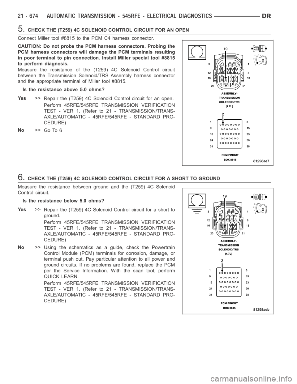
5.CHECK THE (T259) 4C SOLENOID CONTROL CIRCUIT FOR AN OPEN
Connect Miller tool #8815 to the PCM C4 harness connector.
CAUTION: Do not probe the PCM harness connectors. Probing the
PCM harness connectors will damage the PCM terminals resulting
in poor terminal to pin connection. Install Miller special tool #8815
to perform diagnosis.
Measure the resistance of the (T259) 4C Solenoid Control circuit
between the Transmission Solenoid/TRS Assembly harness connector
and the appropriate terminal of Miller tool #8815.
Is the resistance above 5.0 ohms?
Ye s>>
Repair the (T259) 4C Solenoid Control circuit for an open.
Perform 45RFE/545RFE TRANSMISSION VERIFICATION
TEST - VER 1. (Refer to 21 - TRANSMISSION/TRANS-
AXLE/AUTOMATIC - 45RFE/545RFE - STANDARD PRO-
CEDURE)
No>>
Go To 6
6.CHECK THE (T259) 4C SOLENOID CONTROL CIRCUIT FOR A SHORT TO GROUND
Measure the resistance between ground and the (T259) 4C Solenoid
Control circuit.
Is the resistance below 5.0 ohms?
Ye s>>
Repair the (T259) 4C Solenoid Control circuit for a short to
ground.
Perform 45RFE/545RFE TRANSMISSION VERIFICATION
TEST - VER 1. (Refer to 21 - TRANSMISSION/TRANS-
AXLE/AUTOMATIC - 45RFE/545RFE - STANDARD PRO-
CEDURE)
No>>
Using the schematics as a guide, check the Powertrain
Control Module (PCM) terminals for corrosion, damage, or
terminal push out. Pay particular attention to all power and
ground circuits. If no problems are found, replace the PCM
per the Service Information.With the scan tool, perform
QUICK LEARN.
Perform 45RFE/545RFE TRANSMISSION VERIFICATION
TEST - VER 1. (Refer to 21 - TRANSMISSION/TRANS-
AXLE/AUTOMATIC - 45RFE/545RFE - STANDARD PRO-
CEDURE)
Page 3199 of 5267
7.CHECKIFTHEDTCSETINFIRSTGEAR
With the DTC EVENT DATA recorded earlier, check what gear the transmissionwas in when the DTC P0841 was
set.
Does the DTC EVENT DATA show the Present Gear as first gear when the DTC P0841was set ?
Ye s>>
Go To 8
No>>
Replace the Transmission Solenoid/TRS Assembly per the Service Information. (Refer to 21 - TRANS-
MISSION/TRANSAXLE/AUTOMATIC - 45RFE/545RFE/TRANS SOLENOID/TRS ASSY -REMOVAL)
Perform 45RFE/545RFE TRANSMISSION VERIFICATION TEST - VER 1. (Refer to 21- TRANSMIS-
SION/TRANSAXLE/AUTOMATIC - 45RFE/545RFE - STANDARD PROCEDURE)
8.CHECK IF THE NO. 1 CHECK BALL IS CUT OR DAMAGED
Turn the ignition off to the lock position.
Remove the Transmission Valve Body per the Service Information.
Check the No. 1 Check Ball for any possible cuts or damage.
Is the No. 1 Check Ball cut or damaged?
Ye s>>
Replace the No. 1 Check Ball and check for clutch debris in the transmissionoil pan. If there is exces-
sive debris, perform internal repairs to the LR Clutch assembly. Refer to the Service Information for
proper repair procedures.
Perform 45RFE/545RFE TRANSMISSION VERIFICATION TEST - VER 1. (Refer to 21- TRANSMIS-
SION/TRANSAXLE/AUTOMATIC - 45RFE/545RFE - STANDARD PROCEDURE)
No>>
Go To 9
9.CHECK IF THE REVERSE CARRIER SNAP RING IS DISLODGED AND THE TRANSMISSION SOLENOID/
TRS ASSEMBLY
Looking through the windows in the bottom of the case, check whether the snapringatthefrontoftheReverse
(center) Carrier has dislodged.
NOTE: It may be necessary to pry the Input Annulus Gear Shell rearward to check this snap ring.
Is the Reverse Carrier Snap Ring dislodged?
Ye s>>
Repair as necessary.
Perform 45RFE/545RFE TRANSMISSION VERIFICATION TEST - VER 1. (Refer to 21- TRANSMIS-
SION/TRANSAXLE/AUTOMATIC - 45RFE/545RFE - STANDARD PROCEDURE)
No>>
Replace the Transmission Solenoid/TRS Assembly per the Service Information. (Refer to 21 - TRANS-
MISSION/TRANSAXLE/AUTOMATIC - 45RFE/545RFE/TRANS SOLENOID/TRS ASSY -REMOVAL)
Perform 45RFE/545RFE TRANSMISSION VERIFICATION TEST - VER 1. (Refer to 21- TRANSMIS-
SION/TRANSAXLE/AUTOMATIC - 45RFE/545RFE - STANDARD PROCEDURE)