2006 DODGE RAM SRT-10 service
[x] Cancel search: servicePage 3215 of 5267
11 .CHECK THE TRANSMISSION SOLENOID/TRS ASSEMBLY
Using the schematics as a guide, inspect the wiring and connectors specifictothiscircuit.
Wiggle the wires while checking for shorted and open circuits.
Where there any problems found?
Ye s>>
Repair as necessary.
Perform 45RFE/545RFE TRANSMISSION VERIFICATION TEST - VER 1.
No>>
Replace the Transmission Solenoid/TRS Assembly per the Service Information.
Perform 45RFE/545RFE TRANSMISSION VERIFICATION TEST - VER 1. (Refer to 21- TRANSMIS-
SION/TRANSAXLE/AUTOMATIC - 45RFE/545RFE - STANDARD PROCEDURE)
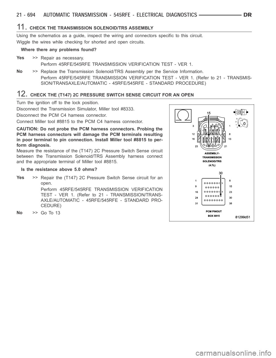
12.CHECK THE (T147) 2C PRESSURE SWITCH SENSE CIRCUIT FOR AN OPEN
Turn the ignition off to the lock position.
Disconnect the Transmission Simulator, Miller tool #8333.
Disconnect the PCM C4 harness connector.
Connect Miller tool #8815 to the PCM C4 harness connector.
CAUTION: Do not probe the PCM harness connectors. Probing the
PCM harness connectors will damage the PCM terminals resulting
in poor terminal to pin connection. Install Miller tool #8815 to per-
form diagnosis.
Measure the resistance of the (T147) 2C Pressure Switch Sense circuit
between the Transmission Solenoid/TRS Assembly harness connect
and the appropriate terminal of Miller tool #8815.
Is the resistance above 5.0 ohms?
Ye s>>
Repair the (T147) 2C Pressure Switch Sense circuit for an
open.
Perform 45RFE/545RFE TRANSMISSION VERIFICATION
TEST - VER 1. (Refer to 21 - TRANSMISSION/TRANS-
AXLE/AUTOMATIC - 45RFE/545RFE - STANDARD PRO-
CEDURE)
No>>
Go To 13
Page 3216 of 5267
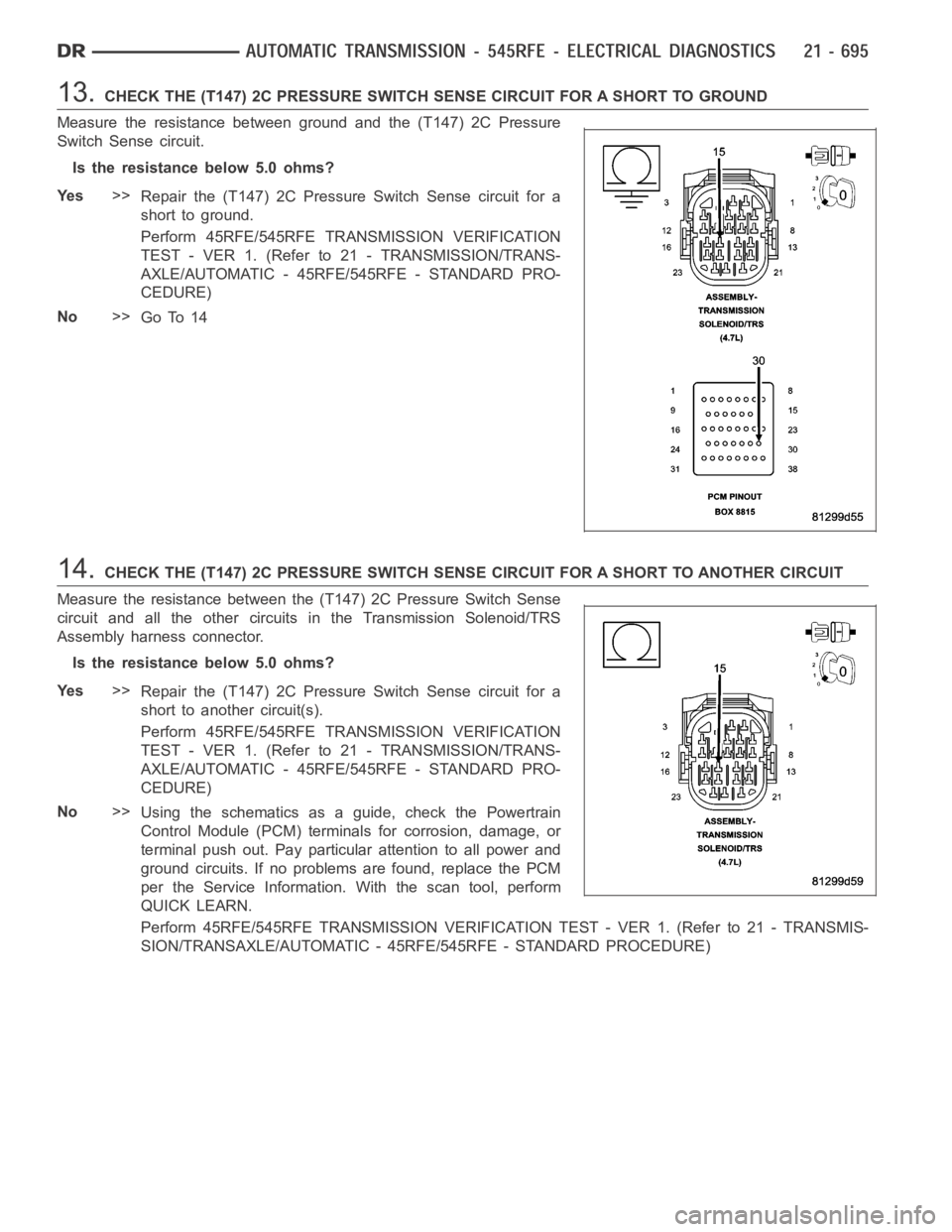
13.CHECK THE (T147) 2C PRESSURE SWITCH SENSE CIRCUIT FOR A SHORT TO GROUND
Measure the resistance between ground and the (T147) 2C Pressure
Switch Sense circuit.
Is the resistance below 5.0 ohms?
Ye s>>
Repair the (T147) 2C Pressure Switch Sense circuit for a
short to ground.
Perform 45RFE/545RFE TRANSMISSION VERIFICATION
TEST - VER 1. (Refer to 21 - TRANSMISSION/TRANS-
AXLE/AUTOMATIC - 45RFE/545RFE - STANDARD PRO-
CEDURE)
No>>
Go To 14
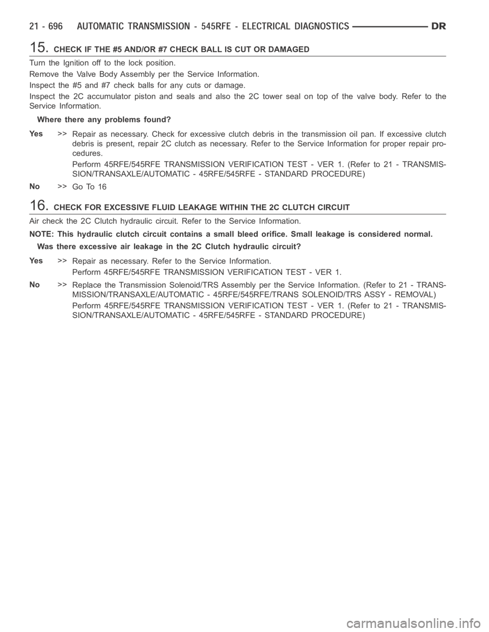
14.CHECK THE (T147) 2C PRESSURE SWITCH SENSE CIRCUIT FOR A SHORT TO ANOTHER CIRCUIT
Measure the resistance between the (T147) 2C Pressure Switch Sense
circuit and all the other circuits in the Transmission Solenoid/TRS
Assembly harness connector.
Is the resistance below 5.0 ohms?
Ye s>>
Repair the (T147) 2C Pressure Switch Sense circuit for a
short to another circuit(s).
Perform 45RFE/545RFE TRANSMISSION VERIFICATION
TEST - VER 1. (Refer to 21 - TRANSMISSION/TRANS-
AXLE/AUTOMATIC - 45RFE/545RFE - STANDARD PRO-
CEDURE)
No>>
Using the schematics as a guide, check the Powertrain
Control Module (PCM) terminals for corrosion, damage, or
terminal push out. Pay particular attention to all power and
ground circuits. If no problems are found, replace the PCM
per the Service Information.With the scan tool, perform
QUICK LEARN.
Perform 45RFE/545RFE TRANSMISSION VERIFICATION TEST - VER 1. (Refer to 21- TRANSMIS-
SION/TRANSAXLE/AUTOMATIC - 45RFE/545RFE - STANDARD PROCEDURE)
Page 3217 of 5267
15.CHECK IF THE #5 AND/OR #7 CHECK BALL IS CUT OR DAMAGED
Turn the Ignition off to the lock position.
Remove the Valve Body Assembly per the Service Information.
Inspect the #5 and #7 check balls for any cuts or damage.
Inspect the 2C accumulator piston and seals and also the 2C tower seal on topof the valve body. Refer to the
Service Information.
Where there any problems found?
Ye s>>
Repair as necessary. Check for excessive clutch debris in the transmission oil pan. If excessive clutch
debris is present, repair 2C clutch as necessary. Refer to the Service Information for proper repair pro-
cedures.
Perform 45RFE/545RFE TRANSMISSION VERIFICATION TEST - VER 1. (Refer to 21- TRANSMIS-
SION/TRANSAXLE/AUTOMATIC - 45RFE/545RFE - STANDARD PROCEDURE)
No>>
Go To 16
16.CHECK FOR EXCESSIVE FLUID LEAKAGE WITHIN THE 2C CLUTCH CIRCUIT
Air check the 2C Clutch hydraulic circuit. Refer to the Service Information.
NOTE: This hydraulic clutch circuit contains a small bleed orifice. Smallleakage is considered normal.
Was there excessive air leakage in the 2C Clutch hydraulic circuit?
Ye s>>
Repair as necessary. Refer to the Service Information.
Perform 45RFE/545RFE TRANSMISSION VERIFICATION TEST - VER 1.
No>>
Replace the Transmission Solenoid/TRS Assembly per the Service Information. (Refer to 21 - TRANS-
MISSION/TRANSAXLE/AUTOMATIC - 45RFE/545RFE/TRANS SOLENOID/TRS ASSY -REMOVAL)
Perform 45RFE/545RFE TRANSMISSION VERIFICATION TEST - VER 1. (Refer to 21- TRANSMIS-
SION/TRANSAXLE/AUTOMATIC - 45RFE/545RFE - STANDARD PROCEDURE)
Page 3221 of 5267
5.CHECK THE LINE PRESSURE SENSOR
Turn the ignition off to the lock position.
Disconnect the Transmission Simulator, Miller tool #8333 and reconnect all previously disconnected connectors.
Install the Line Pressure Adaptor, Miller tool #8259, and the Pressure Gauge, Miller tool #C-3293, 0 to 2000 kPa or
0to300psi.
Start the engine in park.
Monitor the line pressure readings of both the scan tool and the pressure gauge and compare the two readings.
Is the line pressure gauge reading within 34 kPa or 5 psi of the scan tool reading?
Ye s>>
Go To 6
No>>
Replace the Line Pressure Sensor per the Service Information.
Perform 45RFE/545RFE TRANSMISSION VERIFICATION TEST - VER 1. (Refer to 21- TRANSMIS-
SION/TRANSAXLE/AUTOMATIC - 45RFE/545RFE - STANDARD PROCEDURE)
6.CHECK FOR A PLUGGED TRANSMISSION OIL FILTER
Turn the ignition off to the lock position.
Remove and inspect the Transmission Oil Pan for excessive debris per the Service Information.
Remove and inspect the Primary Oil Filter per the Service Information.
NOTE: Make sure the Primary Transmission Oil Filter and/or O-ring is not cracked or split.
Does the Oil Pan contain excessive debris and/or is the Primary Oil Filter cracked or plugged?
Ye s>>
Repair the plugged, cracked, or split Primary Transmission Oil Filter and/or O-ring. If the Primary Trans-
mission Oil Filter is plugged refer to the Service Information for the proper Hydraulic repair procedure.
Perform 45RFE/545RFE TRANSMISSION VERIFICATION TEST - VER 1. (Refer to 21- TRANSMIS-
SION/TRANSAXLE/AUTOMATIC - 45RFE/545RFE - STANDARD PROCEDURE)
No>>
Repair internal transmission and inspect the Transmission Oil Pump per the Service Information and
replace if necessary. If no problem is found, replace the Solenoid/TRS Assembly.
Perform 45RFE/545RFE TRANSMISSION VERIFICATION TEST - VER 1. (Refer to 21- TRANSMIS-
SION/TRANSAXLE/AUTOMATIC - 45RFE/545RFE - STANDARD PROCEDURE)
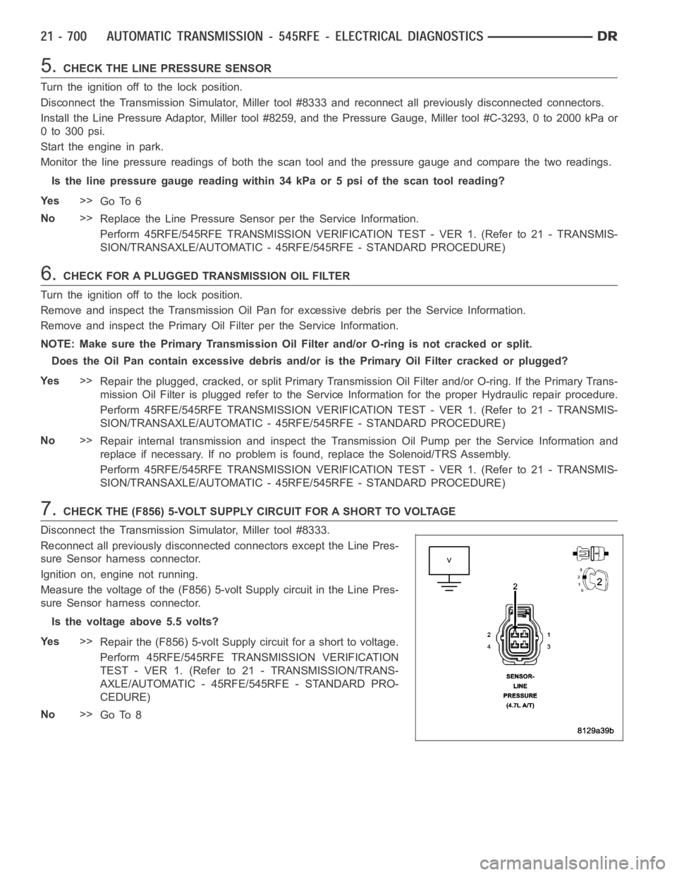
7.CHECK THE (F856) 5-VOLT SUPPLY CIRCUIT FOR A SHORT TO VOLTAGE
Disconnect the Transmission Simulator, Miller tool #8333.
Reconnect all previously disconnected connectors except the Line Pres-
sure Sensor harness connector.
Ignition on, engine not running.
Measure the voltage of the (F856) 5-volt Supply circuit in the Line Pres-
sure Sensor harness connector.
Is the voltage above 5.5 volts?
Ye s>>
Repair the (F856) 5-volt Supply circuit for a short to voltage.
Perform 45RFE/545RFE TRANSMISSION VERIFICATION
TEST - VER 1. (Refer to 21 - TRANSMISSION/TRANS-
AXLE/AUTOMATIC - 45RFE/545RFE - STANDARD PRO-
CEDURE)
No>>
Go To 8
Page 3223 of 5267
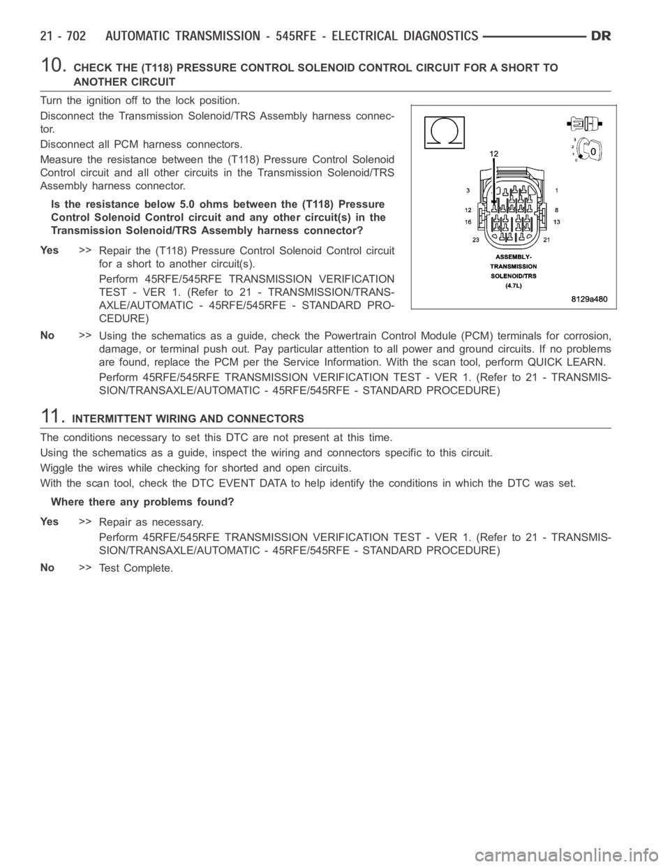
10.CHECK THE (T118) PRESSURE CONTROL SOLENOID CONTROL CIRCUIT FOR A SHORT TO
ANOTHER CIRCUIT
Turn the ignition off to the lock position.
Disconnect the Transmission Solenoid/TRS Assembly harness connec-
tor.
Disconnect all PCM harness connectors.
Measure the resistance between the (T118) Pressure Control Solenoid
Control circuit and all other circuits in the Transmission Solenoid/TRS
Assembly harness connector.
Is the resistance below 5.0 ohms between the (T118) Pressure
Control Solenoid Control circuit and any other circuit(s) in the
Transmission Solenoid/TRS Assembly harness connector?
Ye s>>
Repair the (T118) Pressure Control Solenoid Control circuit
for a short to another circuit(s).
Perform 45RFE/545RFE TRANSMISSION VERIFICATION
TEST - VER 1. (Refer to 21 - TRANSMISSION/TRANS-
AXLE/AUTOMATIC - 45RFE/545RFE - STANDARD PRO-
CEDURE)
No>>
Using the schematics as a guide, check the Powertrain Control Module (PCM)terminals for corrosion,
damage, or terminal push out. Pay particular attention to all power and ground circuits. If no problems
are found, replace the PCM per the Service Information. With the scan tool,perform QUICK LEARN.
Perform 45RFE/545RFE TRANSMISSION VERIFICATION TEST - VER 1. (Refer to 21- TRANSMIS-
SION/TRANSAXLE/AUTOMATIC - 45RFE/545RFE - STANDARD PROCEDURE)
11 .INTERMITTENT WIRING AND CONNECTORS
The conditions necessary to set this DTC are not present at this time.
Using the schematics as a guide, inspect the wiring and connectors specifictothiscircuit.
Wiggle the wires while checking for shorted and open circuits.
With the scan tool, check the DTC EVENT DATA to help identify the conditionsin which the DTC was set.
Where there any problems found?
Ye s>>
Repair as necessary.
Perform 45RFE/545RFE TRANSMISSION VERIFICATION TEST - VER 1. (Refer to 21- TRANSMIS-
SION/TRANSAXLE/AUTOMATIC - 45RFE/545RFE - STANDARD PROCEDURE)
No>>
Te s t C o m p l e t e .
Page 3226 of 5267
3.CHECK THE LINE PRESSURE SENSOR CONNECTION
Ignition on, engine not running.
With the scan tool, monitor the Transmission Line Pressure.
Firmly push the Line Pressure Sensor harness connector inward towards theTransmission.
Did the Line Pressure change to about 207 kPa or 30 psi when the sensor connector was pushed?
Ye s>>
Disconnect and properly reconnect the Line Pressure Sensor connector. Inspect terminals and repair as
necessary.
Perform 45RFE/545RFE TRANSMISSION VERIFICATION TEST - VER 1. (Refer to 21- TRANSMIS-
SION/TRANSAXLE/AUTOMATIC - 45RFE/545RFE - STANDARD PROCEDURE)
No>>
Go To 4
4.CHECK THE PCM AND WIRING
Turn the ignition off to the lock position.
Remove the Ignition Switch Feed fuse from the TIPM.
CAUTION: Removal of the Ignition Switch Feed fuse from the TIPM will prevent the vehicle from being
startedingear.
WARNING: The Ignition Switch Feed fuse must be removed from the TIPM. Failure to do so can result in
personal injury or death.
Install the Transmission Simulator, Miller tool #8333.
With the Transmission Simulator select the
OFFposition on theInput/Output Speedswitch.
Ignition on, engine not running.
With the scan tool, monitor the Line Pressure during the following step.
Using the Transmission Simulator, set the rotary switch to each of the 3 line pressure positions.
NOTE: All three scan tool Line Pressure readings should be steady and ±14 kPa or 2.0 psi of the reading
specified on the Transmission Simulator.
Did the Line Pressure read within ±14 kPA or 2.0 psi in all three positions?
Ye s>>
Go To 5
No>>
Go To 6
5.CHECK THE LINE PRESSURE SENSOR CALIBRATION
Turn the ignition off to the lock position.
Disconnect the Transmission Simulator, Miller tool #8333 and reconnect all previously disconnected connectors.
Install the Line Pressure Adaptor,Miller tool #8259, and Pressure Gauge,Miller tool #C-3293, 0 to 2000 kPa or 0
to 300 psi.
Start the engine in park.
Monitor the Line Pressure readings on the scan tool and the pressure gauge.
Compare the Line Pressure readings between the scan tool and the pressure gauge.
Is the pressure gauge reading within 34 kPa or 5 psi of the scan tool reading?
Ye s>>
Repair the internal transmission and inspect the Transmission Oil Pump per the Service Information and
replace if necessary. If no problem is found, replace the Transmission Solenoid/TRS Assembly, possible
cause is a stuck Pressure Control Solenoid.
Perform 45RFE/545RFE TRANSMISSION VERIFICATION TEST - VER 1. (Refer to 21- TRANSMIS-
SION/TRANSAXLE/AUTOMATIC - 45RFE/545RFE - STANDARD PROCEDURE)
No>>
Replace the Line Pressure Sensor per the Service information.
Perform 45RFE/545RFE TRANSMISSION VERIFICATION TEST - VER 1. (Refer to 21- TRANSMIS-
SION/TRANSAXLE/AUTOMATIC - 45RFE/545RFE - STANDARD PROCEDURE)
Page 3228 of 5267
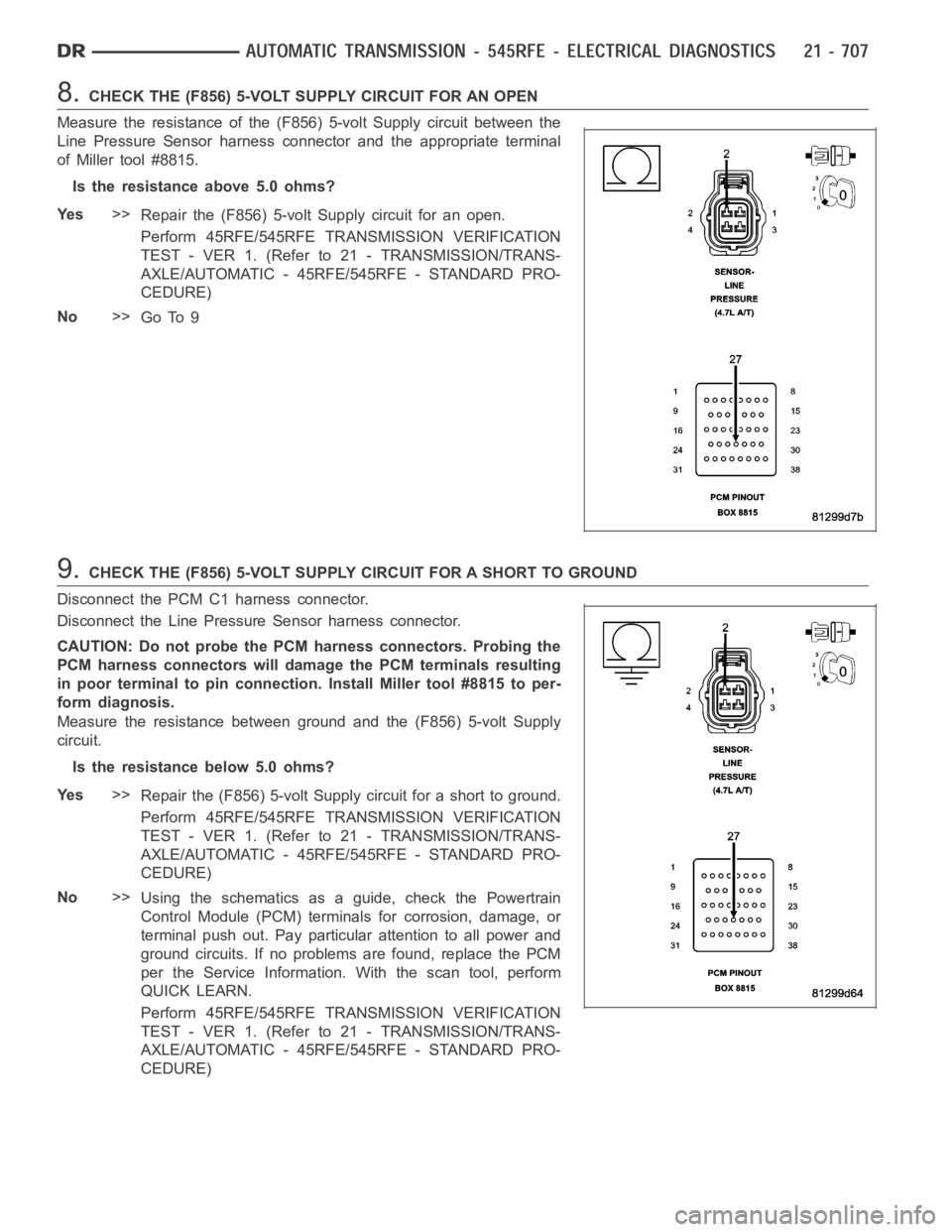
8.CHECK THE (F856) 5-VOLT SUPPLY CIRCUIT FOR AN OPEN
Measure the resistance of the (F856) 5-volt Supply circuit between the
Line Pressure Sensor harness connector and the appropriate terminal
of Miller tool #8815.
Is the resistance above 5.0 ohms?
Ye s>>
Repair the (F856) 5-volt Supply circuit for an open.
Perform 45RFE/545RFE TRANSMISSION VERIFICATION
TEST - VER 1. (Refer to 21 - TRANSMISSION/TRANS-
AXLE/AUTOMATIC - 45RFE/545RFE - STANDARD PRO-
CEDURE)
No>>
Go To 9
9.CHECK THE (F856) 5-VOLT SUPPLY CIRCUIT FOR A SHORT TO GROUND
Disconnect the PCM C1 harness connector.
Disconnect the Line Pressure Sensor harness connector.
CAUTION: Do not probe the PCM harness connectors. Probing the
PCM harness connectors will damage the PCM terminals resulting
in poor terminal to pin connection. Install Miller tool #8815 to per-
form diagnosis.
Measure the resistance between ground and the (F856) 5-volt Supply
circuit.
Is the resistance below 5.0 ohms?
Ye s>>
Repair the (F856) 5-volt Supply circuit for a short to ground.
Perform 45RFE/545RFE TRANSMISSION VERIFICATION
TEST - VER 1. (Refer to 21 - TRANSMISSION/TRANS-
AXLE/AUTOMATIC - 45RFE/545RFE - STANDARD PRO-
CEDURE)
No>>
Using the schematics as a guide, check the Powertrain
Control Module (PCM) terminals for corrosion, damage, or
terminal push out. Pay particular attention to all power and
ground circuits. If no problems are found, replace the PCM
per the Service Information.With the scan tool, perform
QUICK LEARN.
Perform 45RFE/545RFE TRANSMISSION VERIFICATION
TEST - VER 1. (Refer to 21 - TRANSMISSION/TRANS-
AXLE/AUTOMATIC - 45RFE/545RFE - STANDARD PRO-
CEDURE)
Page 3233 of 5267
7.CHECK THE LINE PRESSURE SENSOR OPERATION
Turn the ignition off to the lock position.
Remove the Ignition Switch Feed fuse from the TIPM.
CAUTION: Removal of the Ignition Switch Feed fuse from the TIPM will prevent the vehicle from being
startedingear.
WARNING: The Ignition Switch Feed fuse must be removed from the TIPM. Failure to do so can result in
personal injury or death.
Install the Transmission Simulator, Miller tool #8333.
With the Transmission Simulator select the
OFFposition on theInput/Output Speedswitch.
Ignition on, engine not running.
With the scan tool, monitor the Line Pressure while turning the Pressure Switch selector to each of the 3 line pres-
sure positions on the Transmission Simulator.
NOTE: All three scan tool Line Pressure readings should be steady and ±14 kPa or 2.0 psi of the reading
specified on the Transmission Simulator.
Did the scan tool Line Pressure readings match the specified readings on the Transmission Simulator
and remain steady in all three positions?
Ye s>>
Replace the Line Pressure Sensor per the Service Information.
Perform 45RFE/545RFE TRANSMISSION VERIFICATION TEST - VER 1. (Refer to 21- TRANSMIS-
SION/TRANSAXLE/AUTOMATIC - 45RFE/545RFE - STANDARD PROCEDURE)
No>>
Go To 8
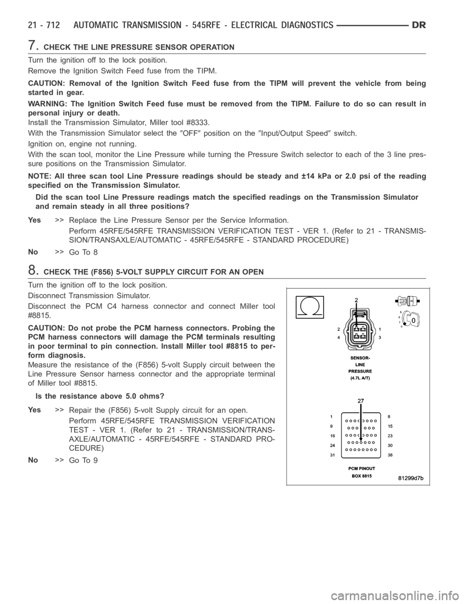
8.CHECK THE (F856) 5-VOLT SUPPLY CIRCUIT FOR AN OPEN
Turn the ignition off to the lock position.
Disconnect Transmission Simulator.
Disconnect the PCM C4 harness connector and connect Miller tool
#8815.
CAUTION: Do not probe the PCM harness connectors. Probing the
PCM harness connectors will damage the PCM terminals resulting
in poor terminal to pin connection. Install Miller tool #8815 to per-
form diagnosis.
Measure the resistance of the (F856) 5-volt Supply circuit between the
Line Pressure Sensor harness connector and the appropriate terminal
of Miller tool #8815.
Is the resistance above 5.0 ohms?
Ye s>>
Repair the (F856) 5-volt Supply circuit for an open.
Perform 45RFE/545RFE TRANSMISSION VERIFICATION
TEST - VER 1. (Refer to 21 - TRANSMISSION/TRANS-
AXLE/AUTOMATIC - 45RFE/545RFE - STANDARD PRO-
CEDURE)
No>>
Go To 9