2006 DODGE RAM SRT-10 service
[x] Cancel search: servicePage 3169 of 5267
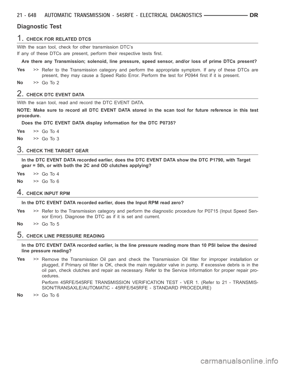
Diagnostic Test
1.CHECKFORRELATEDDTCS
With the scan tool, check for other transmission DTC’s
If any of these DTCs are present, perform their respective tests first.
Are there any Transmission; solenoid, line pressure, speed sensor, and/or loss of prime DTCs present?
Ye s>>
Refer to the Transmission category and perform the appropriate symptom. If any of these DTCs are
present, they may cause a Speed Ratio Error. Perform the test for P0944 firstifitispresent.
No>>
Go To 2
2.CHECK DTC EVENT DATA
With the scan tool, read and record the DTC EVENT DATA.
NOTE: Make sure to record all DTC EVENT DATA stored in the scan tool for future reference in this test
procedure.
Does the DTC EVENT DATA display information for the DTC P0735?
Ye s>>
Go To 4
No>>
Go To 3
3.CHECK THE TARGET GEAR
In the DTC EVENT DATA recorded earlier, does the DTC EVENT DATA show the DTC P1790, with Target
gear = 5th, or with both the 2C and OD clutches applying?
Ye s>>
Go To 4
No>>
Go To 6
4.CHECK INPUT RPM
In the DTC EVENT DATA recorded earlier, does the Input RPM read zero?
Ye s>>
Refer to the Transmission category and perform the diagnostic procedure for P0715 (Input Speed Sen-
sor Error). Diagnose the DTC as if it is set and current.
No>>
Go To 5
5.CHECK LINE PRESSURE READING
In the DTC EVENT DATA recorded earlier, is the line pressure reading more than 10 PSI below the desired
line pressure reading?
Ye s>>
Remove the Transmission Oil pan and check the Transmission Oil filter for improper installation or
plugged, if Primary oil filter is OK, check the main regulator valve in pump. If excessive debris is in the
oil pan, check clutches and repair as necessary. Refer to the Service Information for proper repair pro-
cedures.
Perform 45RFE/545RFE TRANSMISSION VERIFICATION TEST - VER 1. (Refer to 21- TRANSMIS-
SION/TRANSAXLE/AUTOMATIC - 45RFE/545RFE - STANDARD PROCEDURE)
No>>
Go To 6
Page 3170 of 5267
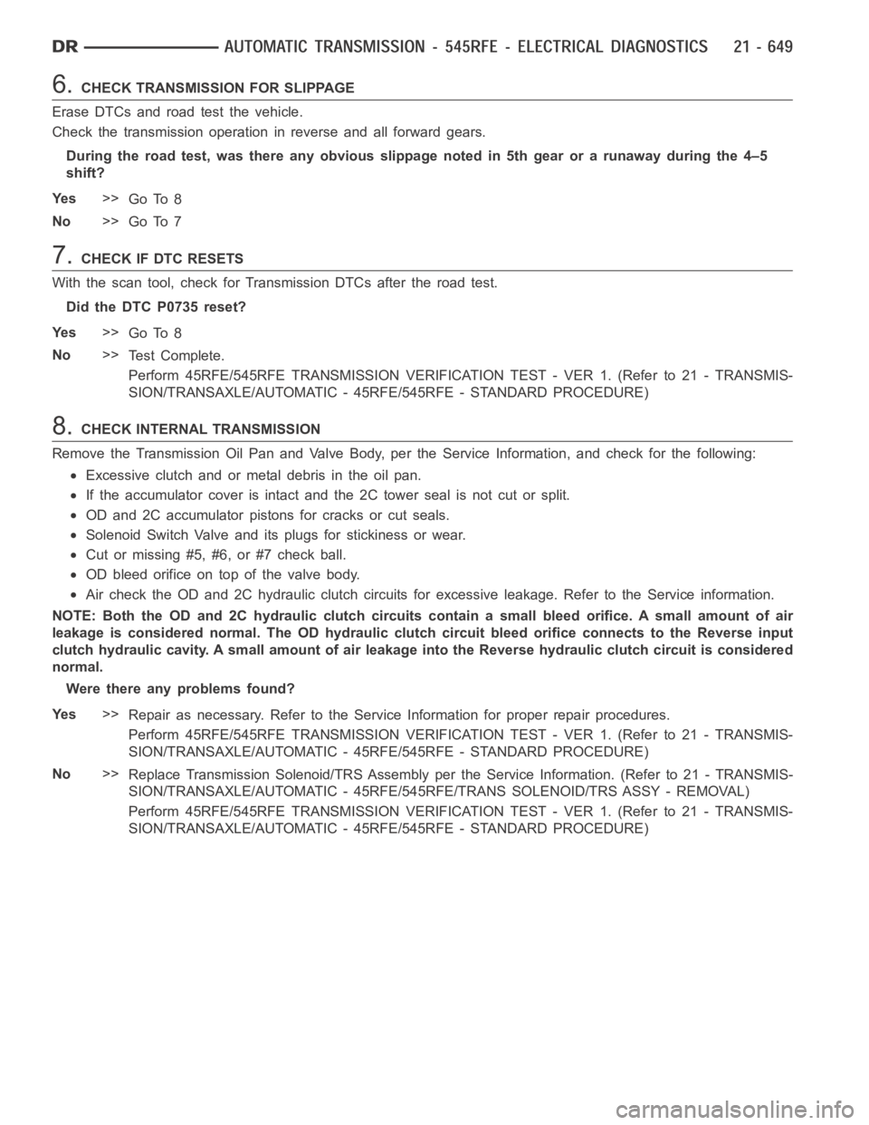
6.CHECK TRANSMISSION FOR SLIPPAGE
Erase DTCs and road test the vehicle.
Check the transmission operation in reverse and all forward gears.
During the road test, was there any obvious slippage noted in 5th gear or a runaway during the 4–5
shift?
Ye s>>
Go To 8
No>>
Go To 7
7.CHECK IF DTC RESETS
With the scan tool, check for Transmission DTCs after the road test.
Did the DTC P0735 reset?
Ye s>>
Go To 8
No>>
Te s t C o m p l e t e .
Perform 45RFE/545RFE TRANSMISSION VERIFICATION TEST - VER 1. (Refer to 21- TRANSMIS-
SION/TRANSAXLE/AUTOMATIC - 45RFE/545RFE - STANDARD PROCEDURE)
8.CHECK INTERNAL TRANSMISSION
Remove the Transmission Oil Pan and Valve Body, per the Service Information, and check for the following:
Excessive clutch and or metal debris in the oil pan.
If the accumulator cover is intact and the 2C tower seal is not cut or split.
OD and 2C accumulator pistons for cracks or cut seals.
Solenoid Switch Valve and its plugs for stickiness or wear.
Cut or missing #5, #6, or #7 check ball.
OD bleed orifice on top of the valve body.
Air check the OD and 2C hydraulic clutch circuits for excessive leakage. Refer to the Service information.
NOTE: Both the OD and 2C hydraulic clutch circuits contain a small bleed orifice. A small amount of air
leakage is considered normal. The OD hydraulic clutch circuit bleed orifice connects to the Reverse input
clutch hydraulic cavity. A small amount of air leakage into the Reverse hydraulic clutch circuit is considered
normal.
Were there any problems found?
Ye s>>
Repair as necessary. Refer to the Service Information for proper repair procedures.
Perform 45RFE/545RFE TRANSMISSION VERIFICATION TEST - VER 1. (Refer to 21- TRANSMIS-
SION/TRANSAXLE/AUTOMATIC - 45RFE/545RFE - STANDARD PROCEDURE)
No>>
Replace Transmission Solenoid/TRS Assembly per the Service Information. (Refer to 21 - TRANSMIS-
SION/TRANSAXLE/AUTOMATIC - 45RFE/545RFE/TRANS SOLENOID/TRS ASSY - REMOVAL)
Perform 45RFE/545RFE TRANSMISSION VERIFICATION TEST - VER 1. (Refer to 21- TRANSMIS-
SION/TRANSAXLE/AUTOMATIC - 45RFE/545RFE - STANDARD PROCEDURE)
Page 3172 of 5267
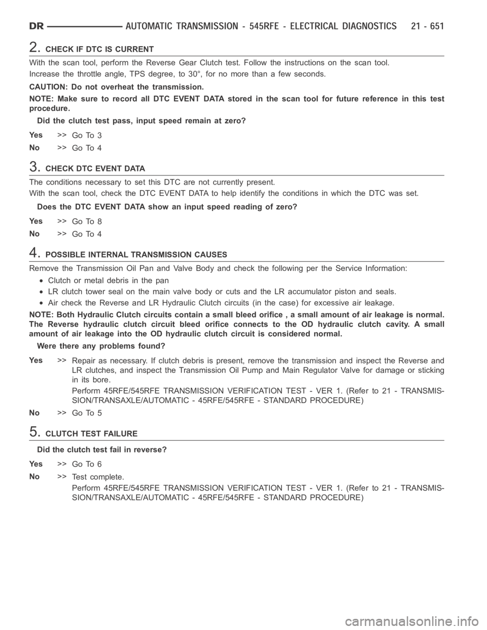
2.CHECK IF DTC IS CURRENT
With the scan tool, perform the Reverse Gear Clutch test. Follow the instructions on the scan tool.
Increase the throttle angle, TPS degree, to 30°, for no more than a few seconds.
CAUTION: Do not overheat the transmission.
NOTE: Make sure to record all DTC EVENT DATA stored in the scan tool for future reference in this test
procedure.
Did the clutch test pass, input speed remain at zero?
Ye s>>
Go To 3
No>>
Go To 4
3.CHECK DTC EVENT DATA
The conditions necessary to set this DTC are not currently present.
With the scan tool, check the DTC EVENT DATA to help identify the conditionsin which the DTC was set.
Does the DTC EVENT DATA show an input speed reading of zero?
Ye s>>
Go To 8
No>>
Go To 4
4.POSSIBLE INTERNAL TRANSMISSION CAUSES
Remove the Transmission Oil Pan and Valve Body and check the following per the Service Information:
Clutch or metal debris in the pan
LR clutch tower seal on the main valve body or cuts and the LR accumulator piston and seals.
Air check the Reverse and LR Hydraulic Clutch circuits (in the case) for excessive air leakage.
NOTE: Both Hydraulic Clutch circuitscontain a small bleed orifice , a small amount of air leakage is normal.
The Reverse hydraulic clutch circuit bleed orifice connects to the OD hydraulic clutch cavity. A small
amount of air leakage into the OD hydraulic clutch circuit is considered normal.
Were there any problems found?
Ye s>>
Repair as necessary. If clutch debris is present, remove the transmissionand inspect the Reverse and
LR clutches, and inspect the Transmission Oil Pump and Main Regulator Valve for damage or sticking
in its bore.
Perform 45RFE/545RFE TRANSMISSION VERIFICATION TEST - VER 1. (Refer to 21- TRANSMIS-
SION/TRANSAXLE/AUTOMATIC - 45RFE/545RFE - STANDARD PROCEDURE)
No>>
Go To 5
5.CLUTCH TEST FAILURE
Did the clutch test fail in reverse?
Ye s>>
Go To 6
No>>
Te s t c o m p l e t e .
Perform 45RFE/545RFE TRANSMISSION VERIFICATION TEST - VER 1. (Refer to 21- TRANSMIS-
SION/TRANSAXLE/AUTOMATIC - 45RFE/545RFE - STANDARD PROCEDURE)
Page 3173 of 5267
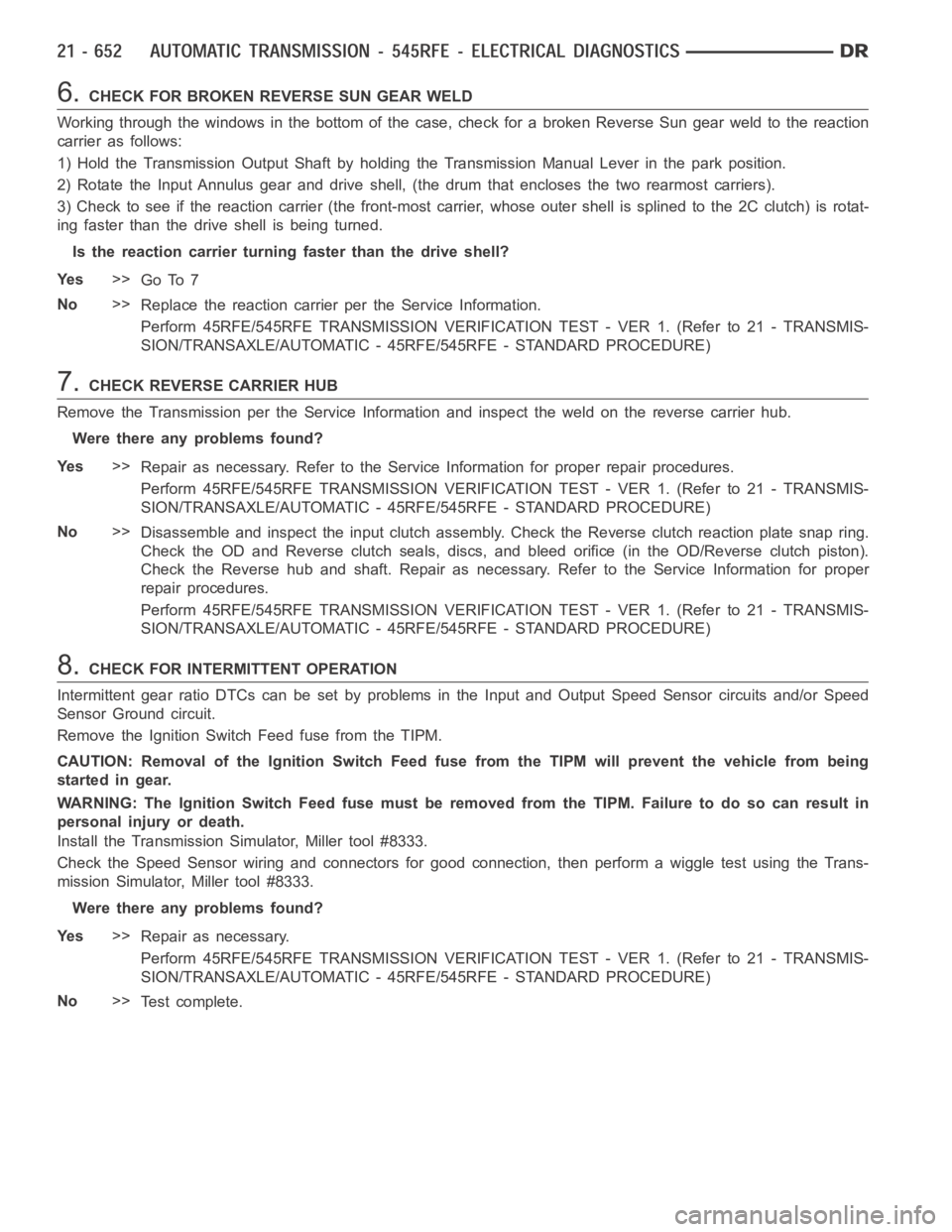
6.CHECK FOR BROKEN REVERSE SUN GEAR WELD
Working through the windows in the bottom of the case, check for a broken Reverse Sun gear weld to the reaction
carrier as follows:
1) Hold the Transmission Output Shaft by holding the Transmission Manual Lever in the park position.
2) Rotate the Input Annulus gear and drive shell, (the drum that encloses the two rearmost carriers).
3) Check to see if the reaction carrier (the front-most carrier, whose outer shell is splined to the 2C clutch) is rotat-
ing faster than the drive shell is being turned.
Is the reaction carrier turning faster than the drive shell?
Ye s>>
Go To 7
No>>
Replace the reaction carrier per the Service Information.
Perform 45RFE/545RFE TRANSMISSION VERIFICATION TEST - VER 1. (Refer to 21- TRANSMIS-
SION/TRANSAXLE/AUTOMATIC - 45RFE/545RFE - STANDARD PROCEDURE)
7.CHECK REVERSE CARRIER HUB
Remove the Transmission per the Service Information and inspect the weld on the reverse carrier hub.
Were there any problems found?
Ye s>>
Repair as necessary. Refer to the Service Information for proper repair procedures.
Perform 45RFE/545RFE TRANSMISSION VERIFICATION TEST - VER 1. (Refer to 21- TRANSMIS-
SION/TRANSAXLE/AUTOMATIC - 45RFE/545RFE - STANDARD PROCEDURE)
No>>
Disassemble and inspect the input clutch assembly. Check the Reverse clutch reaction plate snap ring.
Check the OD and Reverse clutch seals, discs, and bleed orifice (in the OD/Reverse clutch piston).
Check the Reverse hub and shaft. Repair as necessary. Refer to the Service Information for proper
repair procedures.
Perform 45RFE/545RFE TRANSMISSION VERIFICATION TEST - VER 1. (Refer to 21- TRANSMIS-
SION/TRANSAXLE/AUTOMATIC - 45RFE/545RFE - STANDARD PROCEDURE)
8.CHECK FOR INTERMITTENT OPERATION
Intermittent gear ratio DTCs can be set by problems in the Input and Output Speed Sensor circuits and/or Speed
Sensor Ground circuit.
Remove the Ignition Switch Feed fuse from the TIPM.
CAUTION: Removal of the Ignition Switch Feed fuse from the TIPM will prevent the vehicle from being
startedingear.
WARNING: The Ignition Switch Feed fuse must be removed from the TIPM. Failure to do so can result in
personal injury or death.
Install the Transmission Simulator, Miller tool #8333.
Check the Speed Sensor wiring and connectors for good connection, then performawiggletestusingtheTrans-
mission Simulator, Miller tool #8333.
Were there any problems found?
Ye s>>
Repair as necessary.
Perform 45RFE/545RFE TRANSMISSION VERIFICATION TEST - VER 1. (Refer to 21- TRANSMIS-
SION/TRANSAXLE/AUTOMATIC - 45RFE/545RFE - STANDARD PROCEDURE)
No>>
Te s t c o m p l e t e .
Page 3175 of 5267
3.CHECK WIRING AND CONNECTORS
The conditions necessary to set this DTC are not present at this time. Usingthe schematics as a guide, inspect the
wiring and connectors specific to this circuit. Wiggle the wires while checking for shorts and open circuits.
Using the schematics as a guide, inspect the wiring and connectors specifictothiscircuit.
Wiggle the wires while checking for shorts and open circuits.
With the scan tool, check the DTC EVENT DATA to help identify the conditionsin which the DTC was set.
Were there any problems found?
Ye s>>
Repair as necessary.
Perform 45RFE/545RFE TRANSMISSION VERIFICATION TEST - VER 1. (Refer to 21- TRANSMIS-
SION/TRANSAXLE/AUTOMATIC - 45RFE/545RFE - STANDARD PROCEDURE)
No>>
Te s t C o m p l e t e .
4.CHECK THE LR SOLENOID
With the scan tool, check for other transmission DTC’s.
Are the DTCs P1775 and P0841 present also?
Ye s>>
Replace Transmission Solenoid/TRS Assembly per the Service Information. (Refer to 21 - TRANSMIS-
SION/TRANSAXLE/AUTOMATIC - 45RFE/545RFE/TRANS SOLENOID/TRS ASSY - REMOVAL)
Perform 45RFE/545RFE TRANSMISSION VERIFICATION TEST - VER 1. (Refer to 21- TRANSMIS-
SION/TRANSAXLE/AUTOMATIC - 45RFE/545RFE - STANDARD PROCEDURE)
No>>
Go To 5
5.CHECK THE TORQUE CONVERTER AND/OR INTERNAL TRANSMISSION
Repair internal transmission as necessary.
Check for the following possible causes. Refer to the Service informationfor the proper repair procedures.
Inspect the Transmission Oil Pump and Valve Body.
If no problems are found, replace the Transmission Solenoid/TRS Assembly.
Check the Torque Converter Switch Valve and the Torque Converter Clutch Control Valve for sticking in the bore.
Check the Teflon seal rings on the input shaft. Note: If one of the seal ringsis , the loose piece will often lodge in
the TCC switch valve, causing it to stick in it bore.
View repair
Repair
In all cases, replace the Torque Converter. Make sure to check all other possible causes in addition to
the Torque Converter.
Perform 45RFE/545RFE TRANSMISSION VERIFICATION TEST - VER 1. (Refer to 21- TRANSMIS-
SION/TRANSAXLE/AUTOMATIC - 45RFE/545RFE - STANDARD PROCEDURE)
Page 3178 of 5267
Monitor the LR Solenoid LED on the Transmission Simulator.
Did the LR Solenoid LED on the Transmission Simulator blink on and off?
Ye s>>
Go To 3
No>>
Go To 4
3.CHECK THE TRANSMISSION SOLENOID/TRS ASSEMBLY
With the scan tool, continue to actuate the LR Solenoid for the period of 2 minutes with the Transmission Simulator
still connected.
After 2 minutes of actuation, with the scan tool, stop the actuation and check for transmission DTCs.
Did the DTC P0750 reset during the actuation test?
Ye s>>
Go To 4
No>>
Replace the Transmission Solenoid/TRS Assembly per the Service Information. (Refer to 21 - TRANS-
MISSION/TRANSAXLE/AUTOMATIC - 45RFE/545RFE/TRANS SOLENOID/TRS ASSY -REMOVAL)
Perform 45RFE/545RFE TRANSMISSION VERIFICATION TEST - VER 1. (Refer to 21- TRANSMIS-
SION/TRANSAXLE/AUTOMATIC - 45RFE/545RFE - STANDARD PROCEDURE)
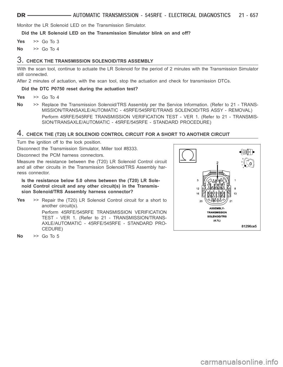
4.CHECK THE (T20) LR SOLENOID CONTROL CIRCUIT FOR A SHORT TO ANOTHER CIRCUIT
Turn the ignition off to the lock position.
Disconnect the Transmission Simulator, Miller tool #8333.
Disconnect the PCM harness connectors.
Measure the resistance between the (T20) LR Solenoid Control circuit
and all other circuits in the Transmission Solenoid/TRS Assembly har-
ness connector.
Is the resistance below 5.0 ohms between the (T20) LR Sole-
noid Control circuit and any other circuit(s) in the Transmis-
sion Solenoid/TRS Assembly harness connector?
Ye s>>
Repair the (T20) LR Solenoid Control circuit for a short to
another circuit(s).
Perform 45RFE/545RFE TRANSMISSION VERIFICATION
TEST - VER 1. (Refer to 21 - TRANSMISSION/TRANS-
AXLE/AUTOMATIC - 45RFE/545RFE - STANDARD PRO-
CEDURE)
No>>
Go To 5
Page 3179 of 5267
5.CHECK THE (T20) LR SOLENOID CONTROL CIRCUIT FOR AN OPEN
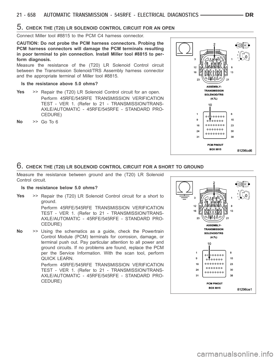
Connect Miller tool #8815 to the PCM C4 harness connector.
CAUTION: Do not probe the PCM harness connectors. Probing the
PCM harness connectors will damage the PCM terminals resulting
in poor terminal to pin connection. Install Miller tool #8815 to per-
form diagnosis.
Measure the resistance of the (T20) LR Solenoid Control circuit
between the Transmission Solenoid/TRS Assembly harness connector
and the appropriate terminal of Miller tool #8815.
Is the resistance above 5.0 ohms?
Ye s>>
Repair the (T20) LR Solenoid Control circuit for an open.
Perform 45RFE/545RFE TRANSMISSION VERIFICATION
TEST - VER 1. (Refer to 21 - TRANSMISSION/TRANS-
AXLE/AUTOMATIC - 45RFE/545RFE - STANDARD PRO-
CEDURE)
No>>
Go To 6
6.CHECK THE (T20) LR SOLENOID CONTROL CIRCUIT FOR A SHORT TO GROUND
Measure the resistance between ground and the (T20) LR Solenoid
Control circuit.
Is the resistance below 5.0 ohms?
Ye s>>
Repair the (T20) LR Solenoid Control circuit for a short to
ground.
Perform 45RFE/545RFE TRANSMISSION VERIFICATION
TEST - VER 1. (Refer to 21 - TRANSMISSION/TRANS-
AXLE/AUTOMATIC - 45RFE/545RFE - STANDARD PRO-
CEDURE)
No>>
Using the schematics as a guide, check the Powertrain
Control Module (PCM) terminals for corrosion, damage, or
terminal push out. Pay particular attention to all power and
ground circuits. If no problems are found, replace the PCM
per the Service Information.With the scan tool, perform
QUICK LEARN.
Perform 45RFE/545RFE TRANSMISSION VERIFICATION
TEST - VER 1. (Refer to 21 - TRANSMISSION/TRANS-
AXLE/AUTOMATIC - 45RFE/545RFE - STANDARD PRO-
CEDURE)
Page 3182 of 5267
3.CHECK THE TRANSMISSION SOLENOID/TRS ASSEMBLY
With the scan tool, continue to actuate the 2C Solenoid for the period of 2 minutes with the Transmission Simulator
still connected.
After 2 minutes of actuation, with the scan tool, stop the actuation and check for transmission DTCs.
Did the DTC P0755 reset during the actuation test?
Ye s>>
Go To 4
No>>
Replace the Transmission Solenoid/TRS Assembly per the Service Information. (Refer to 21 - TRANS-
MISSION/TRANSAXLE/AUTOMATIC - 45RFE/545RFE/TRANS SOLENOID/TRS ASSY -REMOVAL)
Perform 45RFE/545RFE TRANSMISSION VERIFICATION TEST - VER 1. (Refer to 21- TRANSMIS-
SION/TRANSAXLE/AUTOMATIC - 45RFE/545RFE - STANDARD PROCEDURE)
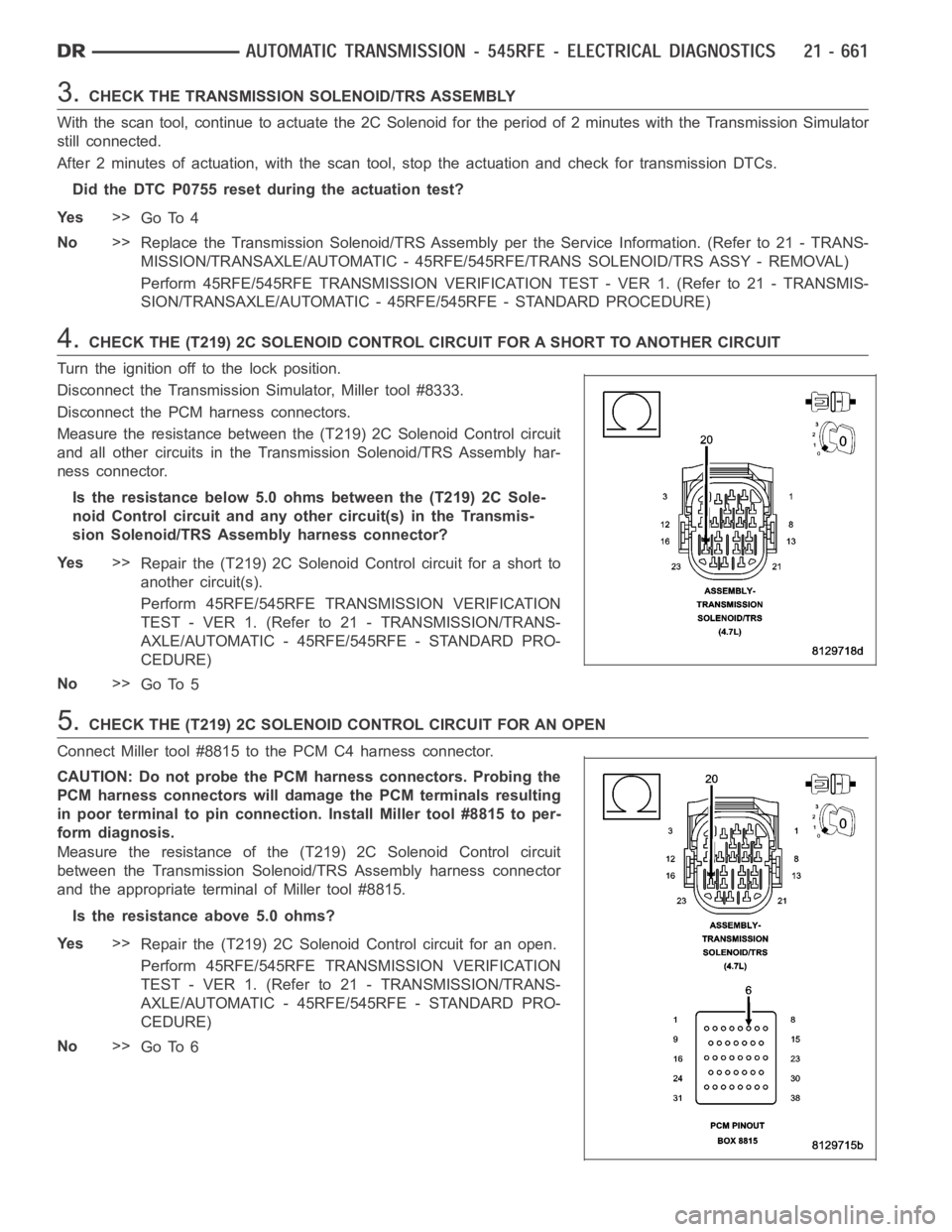
4.CHECK THE (T219) 2C SOLENOID CONTROL CIRCUIT FOR A SHORT TO ANOTHER CIRCUIT
Turn the ignition off to the lock position.
Disconnect the Transmission Simulator, Miller tool #8333.
Disconnect the PCM harness connectors.
Measure the resistance between the (T219) 2C Solenoid Control circuit
and all other circuits in the Transmission Solenoid/TRS Assembly har-
ness connector.
Is the resistance below 5.0 ohms between the (T219) 2C Sole-
noid Control circuit and any other circuit(s) in the Transmis-
sion Solenoid/TRS Assembly harness connector?
Ye s>>
Repair the (T219) 2C Solenoid Control circuit for a short to
another circuit(s).
Perform 45RFE/545RFE TRANSMISSION VERIFICATION
TEST - VER 1. (Refer to 21 - TRANSMISSION/TRANS-
AXLE/AUTOMATIC - 45RFE/545RFE - STANDARD PRO-
CEDURE)
No>>
Go To 5
5.CHECK THE (T219) 2C SOLENOID CONTROL CIRCUIT FOR AN OPEN
Connect Miller tool #8815 to the PCM C4 harness connector.
CAUTION: Do not probe the PCM harness connectors. Probing the
PCM harness connectors will damage the PCM terminals resulting
in poor terminal to pin connection. Install Miller tool #8815 to per-
form diagnosis.
Measure the resistance of the (T219) 2C Solenoid Control circuit
between the Transmission Solenoid/TRS Assembly harness connector
and the appropriate terminal of Miller tool #8815.
Is the resistance above 5.0 ohms?
Ye s>>
Repair the (T219) 2C Solenoid Control circuit for an open.
Perform 45RFE/545RFE TRANSMISSION VERIFICATION
TEST - VER 1. (Refer to 21 - TRANSMISSION/TRANS-
AXLE/AUTOMATIC - 45RFE/545RFE - STANDARD PRO-
CEDURE)
No>>
Go To 6