2006 DODGE RAM SRT-10 service
[x] Cancel search: servicePage 3128 of 5267
Compare the scan tool readings with the numbers listed on the TransmissionSimulator.
Do the readings on the Transmission Simulator match the scan tool readings± 0.2 volts?
Ye s>>
Replace Transmission Solenoid/TRS Assembly per the Service Information.
Perform 45RFE/545RFE TRANSMISSION VERIFICATION TEST - VER 1. (Refer to 21- TRANSMIS-
SION/TRANSAXLE/AUTOMATIC - 45RFE/545RFE - STANDARD PROCEDURE)
No>>
Go To 4
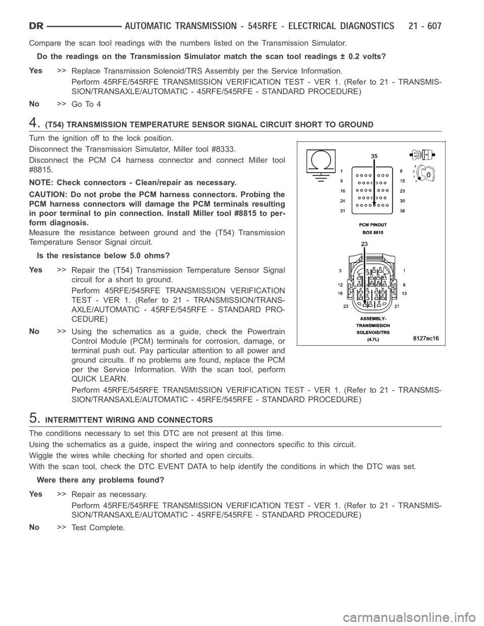
4.(T54) TRANSMISSION TEMPERATURE SENSOR SIGNAL CIRCUIT SHORT TO GROUND
Turn the ignition off to the lock position.
Disconnect the Transmission Simulator, Miller tool #8333.
Disconnect the PCM C4 harness connector and connect Miller tool
#8815.
NOTE: Check connectors - Clean/repair as necessary.
CAUTION: Do not probe the PCM harness connectors. Probing the
PCM harness connectors will damage the PCM terminals resulting
in poor terminal to pin connection. Install Miller tool #8815 to per-
form diagnosis.
Measure the resistance between ground and the (T54) Transmission
Temperature Sensor Signal circuit.
Is the resistance below 5.0 ohms?
Ye s>>
Repair the (T54) Transmission Temperature Sensor Signal
circuit for a short to ground.
Perform 45RFE/545RFE TRANSMISSION VERIFICATION
TEST - VER 1. (Refer to 21 - TRANSMISSION/TRANS-
AXLE/AUTOMATIC - 45RFE/545RFE - STANDARD PRO-
CEDURE)
No>>
Using the schematics as a guide, check the Powertrain
Control Module (PCM) terminals for corrosion, damage, or
terminal push out. Pay particular attention to all power and
ground circuits. If no problems are found, replace the PCM
per the Service Information.With the scan tool, perform
QUICK LEARN.
Perform 45RFE/545RFE TRANSMISSION VERIFICATION TEST - VER 1. (Refer to 21- TRANSMIS-
SION/TRANSAXLE/AUTOMATIC - 45RFE/545RFE - STANDARD PROCEDURE)
5.INTERMITTENT WIRING AND CONNECTORS
The conditions necessary to set this DTC are not present at this time.
Using the schematics as a guide, inspect the wiring and connectors specifictothiscircuit.
Wiggle the wires while checking for shorted and open circuits.
With the scan tool, check the DTC EVENT DATA to help identify the conditionsin which the DTC was set.
Were there any problems found?
Ye s>>
Repair as necessary.
Perform 45RFE/545RFE TRANSMISSION VERIFICATION TEST - VER 1. (Refer to 21- TRANSMIS-
SION/TRANSAXLE/AUTOMATIC - 45RFE/545RFE - STANDARD PROCEDURE)
No>>
Te s t C o m p l e t e .
Page 3131 of 5267
Compare the scan tool readings with the numbers listed on the TransmissionSimulator.
Do the readings on the Transmission Simulator match the scan tool readings± 0.2 volts?
Ye s>>
Replace Transmission Solenoid/TRS assembly per the Service Information.
Perform 45RFE/545RFE TRANSMISSION VERIFICATION TEST - VER 1. (Refer to 21- TRANSMIS-
SION/TRANSAXLE/AUTOMATIC - 45RFE/545RFE - STANDARD PROCEDURE)
No>>
Go To 4
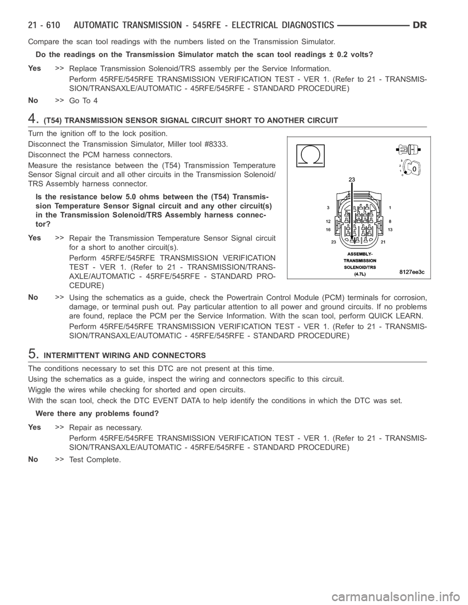
4.(T54) TRANSMISSION SENSOR SIGNAL CIRCUIT SHORT TO ANOTHER CIRCUIT
Turn the ignition off to the lock position.
Disconnect the Transmission Simulator, Miller tool #8333.
Disconnect the PCM harness connectors.
Measure the resistance between the (T54) Transmission Temperature
Sensor Signal circuit and all other circuits in the Transmission Solenoid/
TRS Assembly harness connector.
Is the resistance below 5.0 ohms between the (T54) Transmis-
sion Temperature Sensor Signal circuit and any other circuit(s)
in the Transmission Solenoid/TRS Assembly harness connec-
tor?
Ye s>>
Repair the Transmission Temperature Sensor Signal circuit
for a short to another circuit(s).
Perform 45RFE/545RFE TRANSMISSION VERIFICATION
TEST - VER 1. (Refer to 21 - TRANSMISSION/TRANS-
AXLE/AUTOMATIC - 45RFE/545RFE - STANDARD PRO-
CEDURE)
No>>
Using the schematics as a guide, check the Powertrain Control Module (PCM)terminals for corrosion,
damage, or terminal push out. Pay particular attention to all power and ground circuits. If no problems
are found, replace the PCM per the Service Information. With the scan tool,perform QUICK LEARN.
Perform 45RFE/545RFE TRANSMISSION VERIFICATION TEST - VER 1. (Refer to 21- TRANSMIS-
SION/TRANSAXLE/AUTOMATIC - 45RFE/545RFE - STANDARD PROCEDURE)
5.INTERMITTENT WIRING AND CONNECTORS
The conditions necessary to set this DTC are not present at this time.
Using the schematics as a guide, inspect the wiring and connectors specifictothiscircuit.
Wiggle the wires while checking for shorted and open circuits.
With the scan tool, check the DTC EVENT DATA to help identify the conditionsin which the DTC was set.
Were there any problems found?
Ye s>>
Repair as necessary.
Perform 45RFE/545RFE TRANSMISSION VERIFICATION TEST - VER 1. (Refer to 21- TRANSMIS-
SION/TRANSAXLE/AUTOMATIC - 45RFE/545RFE - STANDARD PROCEDURE)
No>>
Te s t C o m p l e t e .
Page 3134 of 5267
Compare the scan tool readings with the numbers listed on the TransmissionSimulator.
Do the readings on the Transmission Simulator match a non-fluctuating scan tool reading ± 0.2 volts?
Ye s>>
Replace the Transmission Solenoid/TRS Assembly per the Service Information. (Refer to 21 - TRANS-
MISSION/TRANSAXLE/AUTOMATIC - 45RFE/545RFE/TRANS SOLENOID/TRS ASSY -REMOVAL)
Perform 45RFE/545RFE TRANSMISSION VERIFICATION TEST - VER 1. (Refer to 21- TRANSMIS-
SION/TRANSAXLE/AUTOMATIC - 45RFE/545RFE - STANDARD PROCEDURE)
No>>
Using the schematics as a guide, check the Powertrain Control Module (PCM)terminals for corrosion,
damage, or terminal push out. Pay particular attention to all power and ground circuits. If no problems
are found, replace the PCM per the Service Information. With the scan tool,perform QUICK LEARN.
Perform 45RFE/545RFE TRANSMISSION VERIFICATION TEST - VER 1. (Refer to 21- TRANSMIS-
SION/TRANSAXLE/AUTOMATIC - 45RFE/545RFE - STANDARD PROCEDURE)
4.INTERMITTENT WIRING AND CONNECTORS
The conditions necessary to set this DTC are not present at this time.
Using the schematics as a guide, inspect the wiring and connectors specifictothiscircuit.
Wiggle the wires while checking for shorted and open circuits.
With the scan tool, check the DTC EVENT DATA to help identify the conditionsin which the DTC was set.
Were there any problems found?
Ye s>>
Repair as necessary.
Perform 45RFE/545RFE TRANSMISSION VERIFICATION TEST - VER 1. (Refer to 21- TRANSMIS-
SION/TRANSAXLE/AUTOMATIC - 45RFE/545RFE - STANDARD PROCEDURE)
No>>
Te s t C o m p l e t e .
Page 3137 of 5267
2.INPUT SPEED SENSOR
Turn the ignition off to the lock position.
Remove the Ignition Switch Feed fuse from the TIPM.
CAUTION: Removal of the Ignition Switch Feed fuse from the TIPM will prevent the vehicle from being
startedingear.
WARNING: The Ignition Switch Feed fuse must be removed from the TIPM. Failure to do so can result in
personal injury or death.
Install the Transmission Simulator, Miller tool #8333.
Ignition on, engine not running.
With the Transmission Simulator, set the selector switch to 3000/1000 andthe Input/Output switch to ON.
With the scan tool, monitor the Input and Output Speed Sensor RPM.
Does the Input speed read 3000 RPM and the Output speed read 1000 RPM ± 50 RPM?
Ye s>>
Replace the Input Speed Sensor per the Service Information.
Perform 45RFE/545RFE TRANSMISSION VERIFICATION TEST - VER 1. (Refer to 21- TRANSMIS-
SION/TRANSAXLE/AUTOMATIC - 45RFE/545RFE - STANDARD PROCEDURE)
No>>
Go To 3
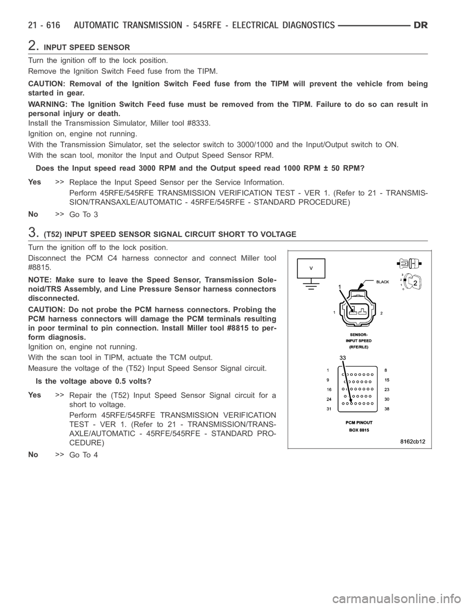
3.(T52) INPUT SPEED SENSOR SIGNAL CIRCUIT SHORT TO VOLTAGE
Turn the ignition off to the lock position.
Disconnect the PCM C4 harness connector and connect Miller tool
#8815.
NOTE: Make sure to leave the Speed Sensor, Transmission Sole-
noid/TRS Assembly, and Line Pressure Sensor harness connectors
disconnected.
CAUTION: Do not probe the PCM harness connectors. Probing the
PCM harness connectors will damage the PCM terminals resulting
in poor terminal to pin connection. Install Miller tool #8815 to per-
form diagnosis.
Ignition on, engine not running.
With the scan tool in TIPM, actuate the TCM output.
Measure the voltage of the (T52) Input Speed Sensor Signal circuit.
Is the voltage above 0.5 volts?
Ye s>>
Repair the (T52) Input Speed Sensor Signal circuit for a
short to voltage.
Perform 45RFE/545RFE TRANSMISSION VERIFICATION
TEST - VER 1. (Refer to 21 - TRANSMISSION/TRANS-
AXLE/AUTOMATIC - 45RFE/545RFE - STANDARD PRO-
CEDURE)
No>>
Go To 4
Page 3140 of 5267
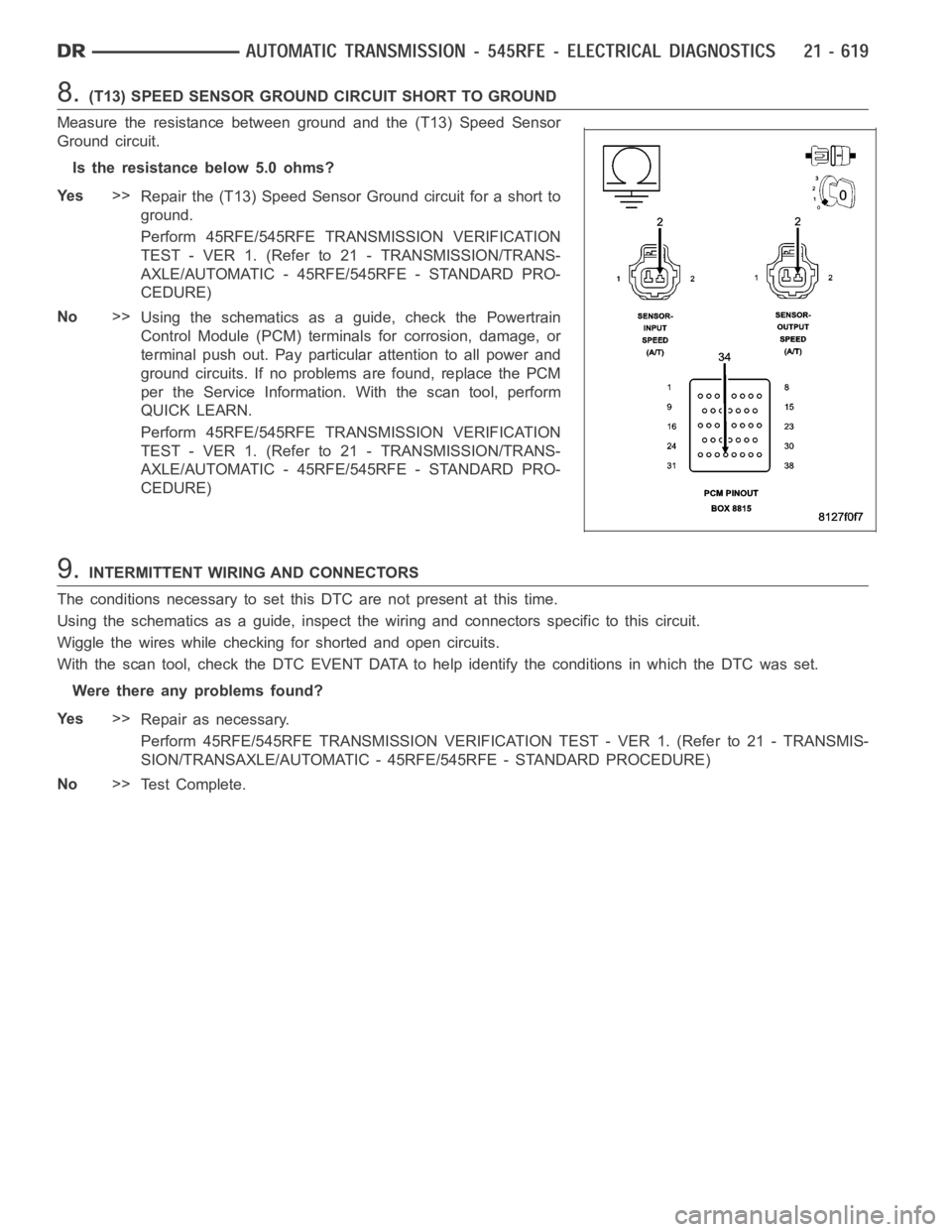
8.(T13) SPEED SENSOR GROUND CIRCUIT SHORT TO GROUND
Measure the resistance between ground and the (T13) Speed Sensor
Ground circuit.
Is the resistance below 5.0 ohms?
Ye s>>
Repair the (T13) Speed Sensor Ground circuit for a short to
ground.
Perform 45RFE/545RFE TRANSMISSION VERIFICATION
TEST - VER 1. (Refer to 21 - TRANSMISSION/TRANS-
AXLE/AUTOMATIC - 45RFE/545RFE - STANDARD PRO-
CEDURE)
No>>
Using the schematics as a guide, check the Powertrain
Control Module (PCM) terminals for corrosion, damage, or
terminal push out. Pay particular attention to all power and
ground circuits. If no problems are found, replace the PCM
per the Service Information.With the scan tool, perform
QUICK LEARN.
Perform 45RFE/545RFE TRANSMISSION VERIFICATION
TEST - VER 1. (Refer to 21 - TRANSMISSION/TRANS-
AXLE/AUTOMATIC - 45RFE/545RFE - STANDARD PRO-
CEDURE)
9.INTERMITTENT WIRING AND CONNECTORS
The conditions necessary to set this DTC are not present at this time.
Using the schematics as a guide, inspect the wiring and connectors specifictothiscircuit.
Wiggle the wires while checking for shorted and open circuits.
With the scan tool, check the DTC EVENT DATA to help identify the conditionsin which the DTC was set.
Were there any problems found?
Ye s>>
Repair as necessary.
Perform 45RFE/545RFE TRANSMISSION VERIFICATION TEST - VER 1. (Refer to 21- TRANSMIS-
SION/TRANSAXLE/AUTOMATIC - 45RFE/545RFE - STANDARD PROCEDURE)
No>>
Te s t C o m p l e t e .
Page 3143 of 5267
2.OUTPUT SPEED SENSOR
Turn the ignition off to the lock position.
Remove the Ignition Switch Feed fuse from the TIPM.
CAUTION: Removal of the Ignition Switch Feed fuse from the TIPM will prevent the vehicle from being
startedingear.
WARNING: The Ignition Switch Feed fuse must be removed from the TIPM. Failure to do so can result in
personal injury or death.
Install the Transmission Simulator, Miller tool #8333.
Ignition on, engine not running.
With the Transmission Simulator, set the selector switch to 3000/1000 andthe Input/Output switch to ON.
With the scan tool, monitor the Input and Output Speed Sensor RPM
Does the Input Speed read 3000 RPM and the Output Speed read 1000 RPM, ± 50 RPM?
Ye s>>
Replace the Output Speed Sensor per the Service Information.
Perform 45RFE/545RFE TRANSMISSION VERIFICATION TEST - VER 1. (Refer to 21- TRANSMIS-
SION/TRANSAXLE/AUTOMATIC - 45RFE/545RFE - STANDARD PROCEDURE)
No>>
Go To 3
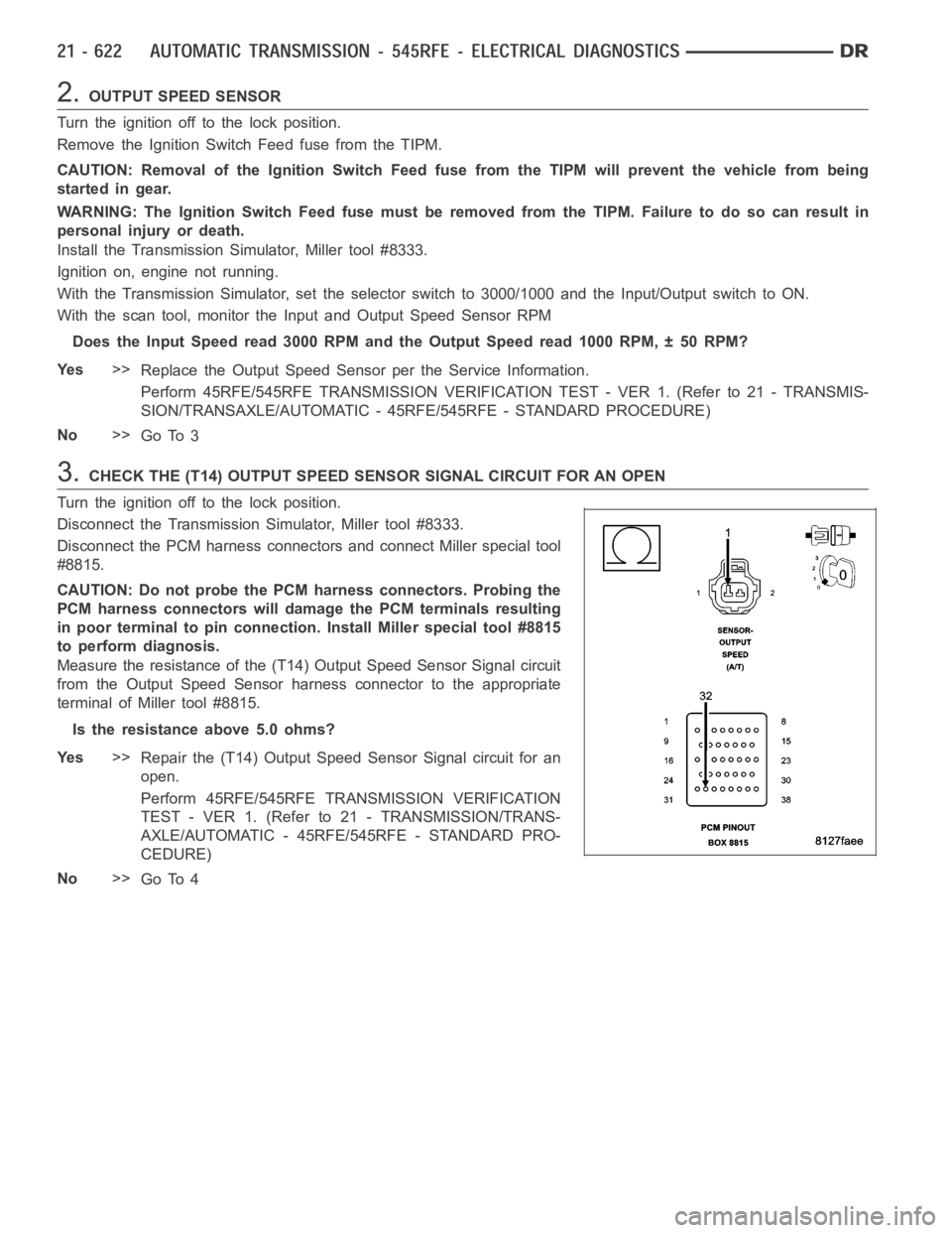
3.CHECK THE (T14) OUTPUT SPEED SENSOR SIGNAL CIRCUIT FOR AN OPEN
Turn the ignition off to the lock position.
Disconnect the Transmission Simulator, Miller tool #8333.
Disconnect the PCM harness connectors and connect Miller special tool
#8815.
CAUTION: Do not probe the PCM harness connectors. Probing the
PCM harness connectors will damage the PCM terminals resulting
in poor terminal to pin connection. Install Miller special tool #8815
to perform diagnosis.
Measure the resistance of the (T14) Output Speed Sensor Signal circuit
from the Output Speed Sensor harness connector to the appropriate
terminal of Miller tool #8815.
Is the resistance above 5.0 ohms?
Ye s>>
Repair the (T14) Output Speed Sensor Signal circuit for an
open.
Perform 45RFE/545RFE TRANSMISSION VERIFICATION
TEST - VER 1. (Refer to 21 - TRANSMISSION/TRANS-
AXLE/AUTOMATIC - 45RFE/545RFE - STANDARD PRO-
CEDURE)
No>>
Go To 4
Page 3146 of 5267
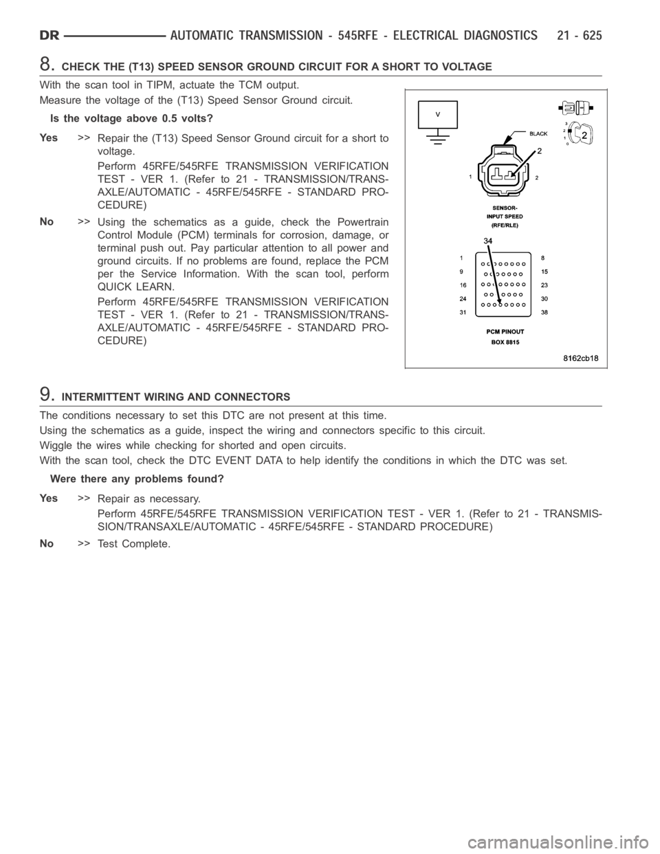
8.CHECK THE (T13) SPEED SENSOR GROUND CIRCUIT FOR A SHORT TO VOLTAGE
With the scan tool in TIPM, actuate the TCM output.
Measure the voltage of the (T13) Speed Sensor Ground circuit.
Is the voltage above 0.5 volts?
Ye s>>
Repair the (T13) Speed Sensor Ground circuit for a short to
voltage.
Perform 45RFE/545RFE TRANSMISSION VERIFICATION
TEST - VER 1. (Refer to 21 - TRANSMISSION/TRANS-
AXLE/AUTOMATIC - 45RFE/545RFE - STANDARD PRO-
CEDURE)
No>>
Using the schematics as a guide, check the Powertrain
Control Module (PCM) terminals for corrosion, damage, or
terminal push out. Pay particular attention to all power and
ground circuits. If no problems are found, replace the PCM
per the Service Information.With the scan tool, perform
QUICK LEARN.
Perform 45RFE/545RFE TRANSMISSION VERIFICATION
TEST - VER 1. (Refer to 21 - TRANSMISSION/TRANS-
AXLE/AUTOMATIC - 45RFE/545RFE - STANDARD PRO-
CEDURE)
9.INTERMITTENT WIRING AND CONNECTORS
The conditions necessary to set this DTC are not present at this time.
Using the schematics as a guide, inspect the wiring and connectors specifictothiscircuit.
Wiggle the wires while checking for shorted and open circuits.
With the scan tool, check the DTC EVENT DATA to help identify the conditionsin which the DTC was set.
Were there any problems found?
Ye s>>
Repair as necessary.
Perform 45RFE/545RFE TRANSMISSION VERIFICATION TEST - VER 1. (Refer to 21- TRANSMIS-
SION/TRANSAXLE/AUTOMATIC - 45RFE/545RFE - STANDARD PROCEDURE)
No>>
Te s t C o m p l e t e .
Page 3147 of 5267
P0725-ENGINE SPEED SENSOR CIRCUIT
For a complete wiring diagramRefer to Section 8W.
When Monitored:
Continuously every 7 msec with the ignition on and engine running.
Set Condition:
This DTC will set when the calculated engine speed is less than 390 RPM with the engine running, or greater
than 8000 RPM, for the period of 2.0 seconds. The PCM will place the Transmission in Limp-in when this DTC
is set.Note: This is not a Transmission Input Speed Sensor DTC.
Possible Causes
RELATED ENGINE DTC’S PRESENT
CRANK POSITION SENSOR OR WIRING
POWERTRAIN CONTROL MODULE
Always perform the 45RFE/545RFE Pre-Diagnostic Troubleshooting Procedure before proceeding. (Refer to
21 - TRANSMISSION/TRANSAXLE/AUTOMATIC - 45RFE/545RFE - STANDARD PROCEDURE)
Theory of Operation
The Transmission Control System calculates the engine RPM by directly reading the engine crank position sensor.
It compares the calculated value to the engine speed sensor signal transmitted from the Engine Control System
over the controllers internal BUS. The calculated engine RPM is also comparedtoaminimumandamaximum
value.Note: Due to the integration of the Powertrain Control Module (PCM) and Transmission Control Mod-
ule (TCM), BUS communication between the modules is internal and unserviceable.
Diagnostic Test
1.CHECKFORRELATEDENGINEDTCS
NOTE: This is not a Transmission Input Speed Sensor DTC.
Ignition on, engine not running.
With the scan tool, read all Engine DTCs. This includes any active or storedor one trip DTCs.
Are there any engine RPM related DTCs present?
Ye s>>
Refer to the Powertrain category and perform the appropriate symptom.
Perform 45RFE/545RFE TRANSMISSION VERIFICATION TEST - VER 1. (Refer to 21- TRANSMIS-
SION/TRANSAXLE/AUTOMATIC - 45RFE/545RFE - STANDARD PROCEDURE)
No>>
Go To 2
2.CHECK IF DTC IS CURRENT
Ignition on, engine not running.
With a scan tool, read and record all DTC EVENT DATA.
Withthescantool,eraseallactiveandstoredtransmissionDTCs.(Note:it may be necessary to perform a battery
disconnect with the scan tool to clear DTC EVENT DATA.)
Using the DTC EVENT DATA, duplicate theconditions in which the original DTCset.
With the scan tool, read transmission and engine DTCs.
NOTE: Refer to all engine DTCs first in the following question.
Pick the answer below that best describes your findings, (this includes one trip failures).
Transmission DTC P0725 set
Using the schematics as a guide, check the Powertrain Control Module (PCM)terminals for corrosion,
damage, or terminal push out. Also check the Crank Position sensor and wiring. Pay particular attention