Page 3911 of 5267
ASSEMBLY
GEARTRAIN AND DIRECT CLUTCH
1. Soak direct clutch and overdrive clutch discs in
Mopar
ATF +4, Automatic Transmission fluid.
Allow discs to soak for 10-20 minutes.
2. Install annulus gear (3) on output shaft, if removed.
Then install annulus gear retaining snap-ring (1).
3. Align and install clutch drum (3) on annulus gear
(1). Be sure drum is engaged in annulus gear lugs.
4. Install clutch drum outer retaining ring (2).
5. Slide clutch drum (3) forward and install inner
retaining ring (2).
Page 3912 of 5267
6. Install rear bearing (1) and snap-ring (2) on output
shaft. Be sure locating ring groove in bearing is
toward rear.
7. Install overrunning clutch (2) on hub (1). Note that
clutch only fits one way. Shoulder on clutch should
seat in small recess at edge of hub.
8. Install thrust bearing on overrunning clutch hub.
Use generous amount of petroleum jelly to hold
bearing in place for installation. Bearing fits one
way only. Be sure bearing is seated squarely
against hub. Reinstall bearing if it does not seat
squarely.
9. Install overrunning clutch (2) in output shaft (6).
Insert snap-ring pliers inhub splines. Expand pliers
to grip hub. Then install assembly with counter-
clockwise, twisting motion.
Page 3914 of 5267
14. Mount assembled output shaft, annulus gear, and
clutch drum in shop press (3). Direct clutch
spring, hub and clutch pack are easier to install
with assembly mounted in press.
15. Align splines in hubs of planetary gear and over-
running clutch with Alignment tool 6227-2 (1).
Insert tool through sun gear and into splines of
both hubs. Be sure alignment tool is fully seated
before proceeding.
16. Install direct clutch spring (2). Be sure spring is
properly seated on spring plate (4).
Page 3915 of 5267
NOTE: The direct clutch in a 48RE transmission
uses 10 double-sided clutch discs.
17. Assemble and install direct clutch pack on hub as
follows:
a. Install direct clutch reaction plate (2) on clutch
hub first. Note that one side of reaction plate is
counterbored (1). Be sure this side faces rear-
ward. Splines at rear of hub (3) are raised
slightly. Counterbore in plate fits over raised
splines. Plate should be flush with this end of
hub (3).
b. Install first friction disc with internal splines, fol-
lowed by a steel seperator disc with external
lugs. Continue alternating internal and external
discs until all discs have been installed.
18. Install pressure plate (1). This is last clutch pack
(2) item to be installed. Be sure plate is installed
with shoulder side facing upward (3).
Page 3916 of 5267

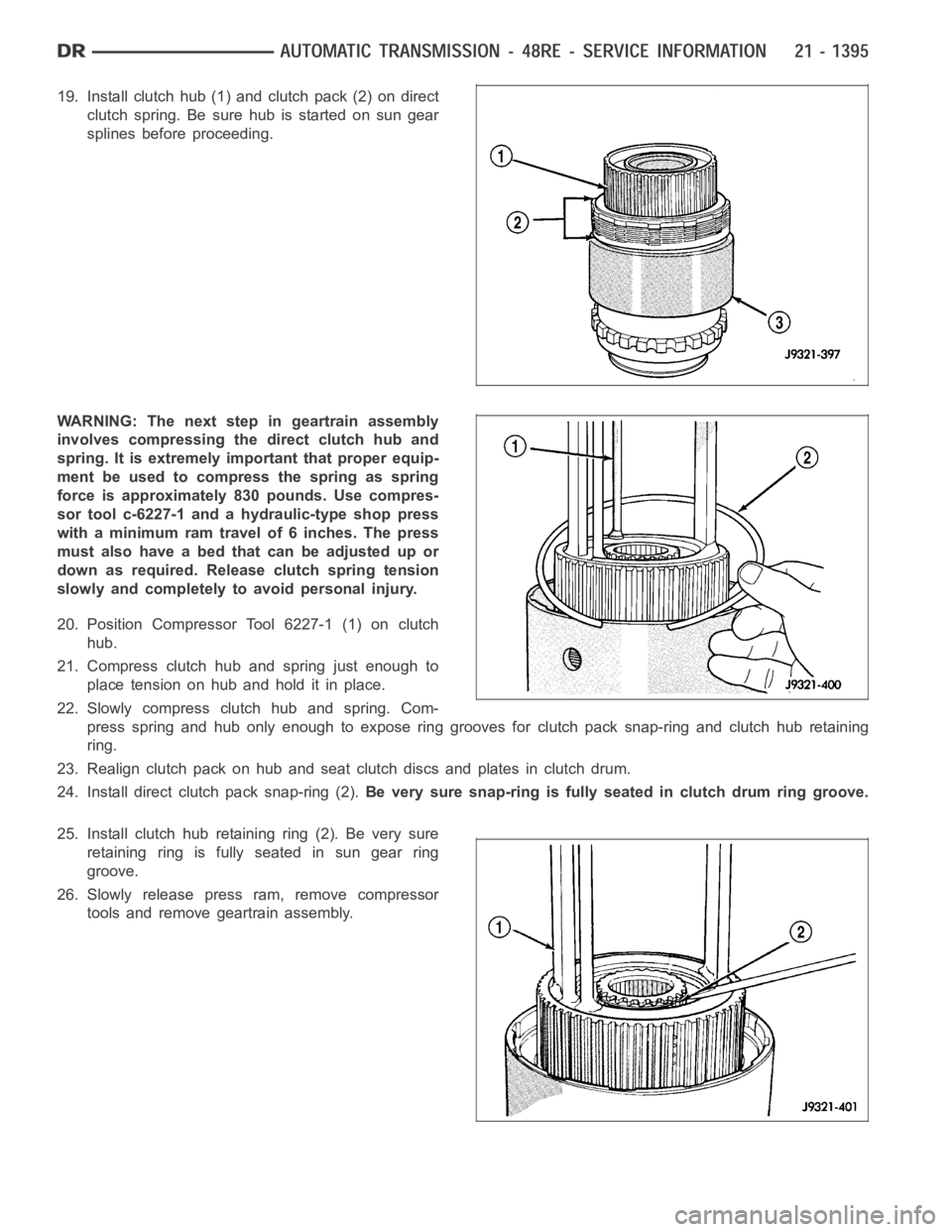
19. Install clutch hub (1) and clutch pack (2) on direct
clutch spring. Be sure hub is started on sun gear
splines before proceeding.
WARNING: The next step in geartrain assembly
involves compressing the direct clutch hub and
spring. It is extremely important that proper equip-
ment be used to compress the spring as spring
force is approximately 830 pounds. Use compres-
sor tool c-6227-1 and a hydraulic-type shop press
with a minimum ram travel of 6 inches. The press
must also have a bed that can be adjusted up or
down as required. Release clutch spring tension
slowly and completely to avoid personal injury.
20. Position Compressor Tool 6227-1 (1) on clutch
hub.
21. Compress clutch hub and spring just enough to
place tension on hub and hold it in place.
22. Slowly compress clutch hub and spring. Com-
press spring and hub only enough to expose ring grooves for clutch pack snap-ring and clutch hub retaining
ring.
23. Realign clutch pack on hub and seat clutch discs and plates in clutch drum.
24. Install direct clutch pack snap-ring (2).Be very sure snap-ring is fully seated in clutch drum ring groove.
25. Install clutch hub retaining ring (2). Be very sure
retaining ring is fully seated in sun gear ring
groove.
26. Slowly release press ram, remove compressor
tools and remove geartrain assembly.
Page 3918 of 5267
6. Support geartrain on Tool 6227-1. Be sure tool is
securely seated in clutch hub.
7. Install overdrive gear case (2) on geartrain (1).
8. Expand front bearing locating ring with snap-ring
pliers (1). Then slide case downward until locating
ring locks in bearing groove and release snap-ring.
9. Install locating ring access cover, gasket and
screws (2) in overdrive unit case.
OVERDRIVE CLUTCH
NOTE: The overdrive clutch in a 48RE transmis-
sion uses 5 or 6 clutch discs depending on the
application.
1. Install overdrive clutch reaction ring (1) first. Reac-
tion ring is flat with notched ends.
Page 3919 of 5267

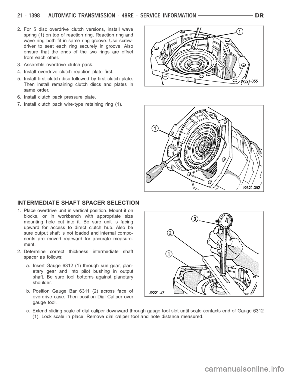
2. For 5 disc overdrive clutch versions, install wave
spring (1) on top of reaction ring. Reaction ring and
waveringbothfitinsameringgroove.Usescrew-
driver to seat each ring securely in groove. Also
ensure that the ends of the two rings are offset
from each other.
3. Assemble overdrive clutch pack.
4. Install overdrive clutch reaction plate first.
5. Install first clutch disc followed by first clutch plate.
Then install remaining clutch discs and plates in
same order.
6. Install clutch pack pressure plate.
7. Install clutch pack wire-type retaining ring (1).
INTERMEDIATE SHAFT SPACER SELECTION
1. Place overdrive unit in vertical position. Mount it on
blocks, or in workbench with appropriate size
mounting hole cut into it. Be sure unit is facing
upward for access to direct clutch hub. Also be
sure output shaft is not loaded and internal compo-
nents are moved rearward for accurate measure-
ment.
2. Determine correct thickness intermediate shaft
spacer as follows:
a. Insert Gauge 6312 (1) through sun gear, plan-
etary gear and into pilot bushing in output
shaft. Be sure tool bottoms against planetary
shoulder.
b. Position Gauge Bar 6311 (2) across face of
overdrive case. Then position Dial Caliper over
gauge tool.
c. Extend sliding scale of dial caliper downward through gauge tool slot until scale contacts end of Gauge 6312
(1). Lock scale in place. Remove dial caliper tool and note distance measured.
Page 3920 of 5267

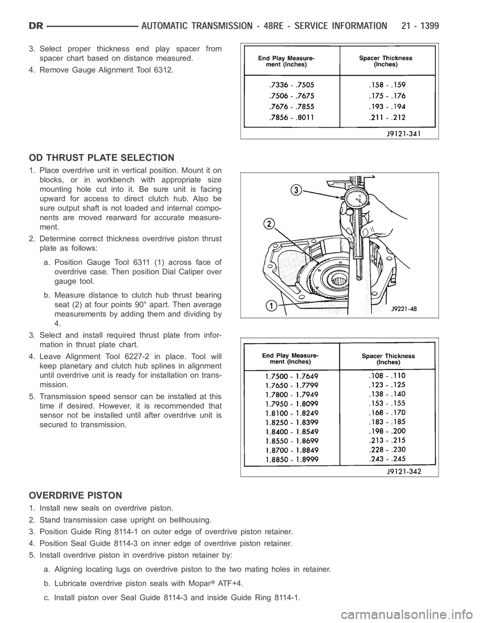
3. Select proper thickness end play spacer from
spacer chart based on distance measured.
4. Remove Gauge Alignment Tool 6312.
OD THRUST PLATE SELECTION
1. Place overdrive unit in vertical position. Mount it on
blocks, or in workbench with appropriate size
mounting hole cut into it. Be sure unit is facing
upward for access to direct clutch hub. Also be
sure output shaft is not loaded and internal compo-
nents are moved rearward for accurate measure-
ment.
2. Determine correct thickness overdrive piston thrust
plate as follows:
a. Position Gauge Tool 6311 (1) across face of
overdrive case. Then position Dial Caliper over
gauge tool.
b. Measure distance to clutch hub thrust bearing
seat (2) at four points 90° apart. Then average
measurements by adding them and dividing by
4.
3. Select and install required thrust plate from infor-
mation in thrust plate chart.
4. Leave Alignment Tool 6227-2 in place. Tool will
keep planetary and clutch hub splines in alignment
until overdrive unit is ready for installation on trans-
mission.
5. Transmission speed sensor can be installed at this
time if desired. However, it is recommended that
sensor not be installed until after overdrive unit is
secured to transmission.
OVERDRIVE PISTON
1. Install new seals on overdrive piston.
2. Stand transmission case upright on bellhousing.
3. Position Guide Ring 8114-1 on outer edge of overdrive piston retainer.
4. Position Seal Guide 8114-3 on inner edge of overdrive piston retainer.
5. Install overdrive piston in overdrive piston retainer by:
a. Aligning locating lugs on overdrive piston to the two mating holes in retainer.
b. Lubricate overdrive piston seals with Mopar
ATF+4.
c. Install piston over Seal Guide 8114-3 and inside Guide Ring 8114-1.