Page 3972 of 5267
3-4 shift valve
3-4 timing valve
3-4 quick fill valve
3-4 accumulator
Converter clutch lock-up valve
Converter clutch lock-up timing Valve
OPERATION
NOTE: Refer to the Hydraulic Schematics for a visual aid in determining valve location, operation and
design.
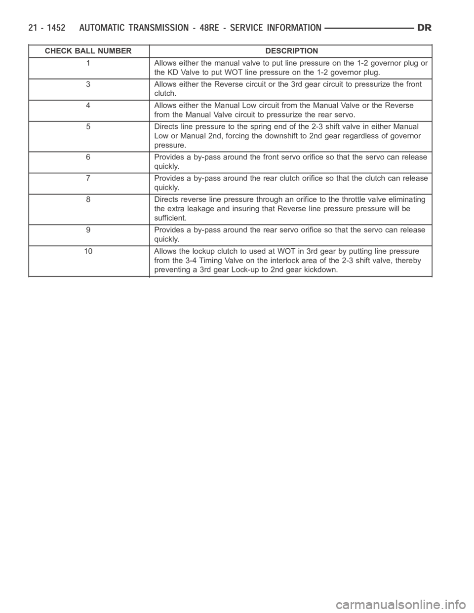
CHECK BALLS
Lower Housing Shift Valves and Springs
1 - 3-4 ACCUMULATOR HOUSING 11 - TIMING VALVE COVER
2 - 3-4 SHIFT VALVE AND SPRING 12 - PLUG
3 - PLUG 13 - 3-4 TIMING VALVE AND SPRING
4 - SPRING RETAINER 14 - LOWER HOUSING
5 - CONVERTER CLUTCH VALVE AND SPRING 15 - ACCUMULATOR END PLATE
6 - CONVERTER CLUTCH TIMING VALVE AND SPRING 16 - 3-4 ACCUMULATOR PISTON ANDSPRING
7 - OVERDRIVE SEPARATOR PLATE 17 - E-CLIP
8 - CASE CONNECTOR 18 - 3-4 QUICK FILL SPRING AND VALVE
9 - CONVERTER CLUTCH SOLENOID 19 - SOLENOID GASKET
10 - OVERDRIVE SOLENOID 20 - HARNESS
Page 3973 of 5267

CHECK BALL NUMBER DESCRIPTION
1 Allows either the manual valve to put line pressure on the 1-2 governor plugor
the KD Valve to put WOT line pressure on the 1-2 governor plug.
3 Allows either the Reverse circuit or the 3rd gear circuit to pressurize thefront
clutch.
4 Allows either the Manual Low circuit from the Manual Valve or the Reverse
from the Manual Valve circuit to pressurize the rear servo.
5 Directs line pressure to the spring end of the 2-3 shift valve in either Manual
Low or Manual 2nd, forcing the downshift to 2nd gear regardless of governor
pressure.
6 Provides a by-pass around the front servo orifice so that the servo can release
quickly.
7 Provides a by-pass around the rear clutch orifice so that the clutch can release
quickly.
8 Directs reverse line pressure through an orifice to the throttle valve eliminating
the extra leakage and insuring that Reverse line pressure pressure will be
sufficient.
9 Provides a by-pass around the rear servo orifice so that the servo can release
quickly.
10 AllowsthelockupclutchtousedatWOTin3rdgearbyputtinglinepressure
from the 3-4 Timing Valve on the interlock area of the 2-3 shift valve, thereby
preventing a 3rd gear Lock-up to 2nd gear kickdown.
Page 3982 of 5267

2-3 shift valve is larger in diameter than the 1-2 shift valve, the 2-3 shiftwill always happen at a greater speed than
the 1-2 shift. When this happens, the governor plug is forced against the shift valve moving it to the right. The shift
valve causes land #4 to close the passage supplying throttle pressure to the 2-3 shift valve. Without throttle pres-
sure present in the circuit now, the governor plug will push the valve over far enough to bottom the valve in its bore.
This allows land #2 to direct line pressure to the front clutch.
After the shift , line pressure is directed to the release side of the kickdown servo. This releases the front band and
applies the front clutch, shifting into third gear or direct drive. The rear clutch remains applied, as it has been in the
other gears. During a manual “1” or manual “2” gear selection, line pressure is sent between the two lands of the
2-3 governor plug. This line pressure at the governor plug locks the shift valve into the second gear position, pre-
venting an upshift into direct drive. The theory for the blocking of the valve is the same as that of the 1-2 shift valve.
If the manual “2” or manual “1” gear position is selected from the drive position, the PCM will control the timing of
the downshift by targeting for a high governor pressure. When a safe vehicle speed is reached, the PCM will switch
to its normal control governor curve and the downshift will occur.
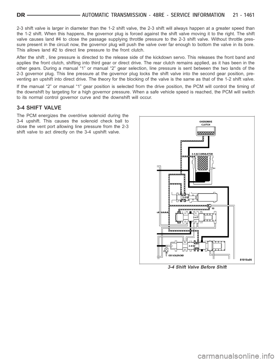
3-4 SHIFT VALVE
The PCM energizes the overdrive solenoid during the
3-4 upshift. This causes the solenoid check ball to
close the vent port allowing line pressure from the 2-3
shift valve to act directly on the 3-4 upshift valve.
3-4ShiftValveBeforeShift
Page 3984 of 5267
3-4 TIMING VALVE
The 3-4 timing valve is moved by line pressure com-
ing through the 3-4 shift valve or the converter clutch
valve.
3-4 Shift Valve After Shift
Page 3985 of 5267
After the shift, the timing valve holds the 2-3 shift
valve in an upshift position. The purpose is to prevent
the 2-3 valve from downshifting while either the over-
drive clutch or converter clutch is applied.
3-4ShiftValveBeforeShift
Page 3986 of 5267
3-4 QUICK FILL VALVE
The 3-4 quick fill valve provides faster engagement of
the overdrive clutch during 3-4 upshifts. The valve
temporarily bypasses the clutch piston feed orifice at
the start of a 3-4 upshift.
3-4ShiftValveBeforeShift
Page 3987 of 5267

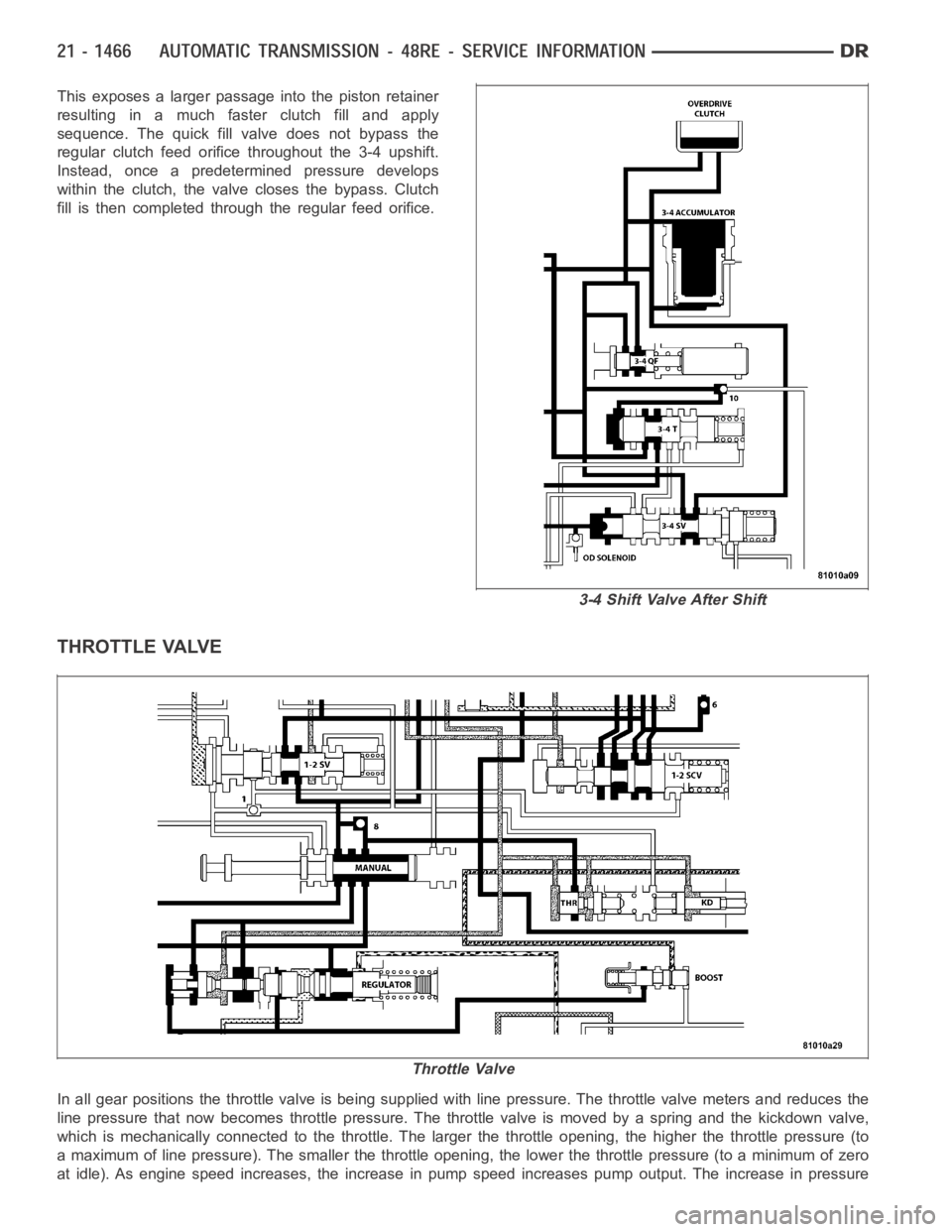
This exposes a larger passage into the piston retainer
resulting in a much faster clutch fill and apply
sequence. The quick fill valve does not bypass the
regular clutch feed orifice throughout the 3-4 upshift.
Instead, once a predetermined pressure develops
within the clutch, the valve closes the bypass. Clutch
fill is then completed through the regular feed orifice.
THROTTLE VALVE
In all gear positions the throttle valve is being supplied with line pressure. The throttle valve meters and reduces the
line pressure that now becomes throttle pressure. The throttle valve is moved by a spring and the kickdown valve,
which is mechanically connected to the throttle. The larger the throttle opening, the higher the throttle pressure (to
a maximum of line pressure). The smaller the throttle opening, the lower thethrottlepressure(toaminimumofzero
at idle). As engine speed increases, the increase in pump speed increases pump output. The increase in pressure
3-4 Shift Valve After Shift
Throttle Valve
Page 3991 of 5267

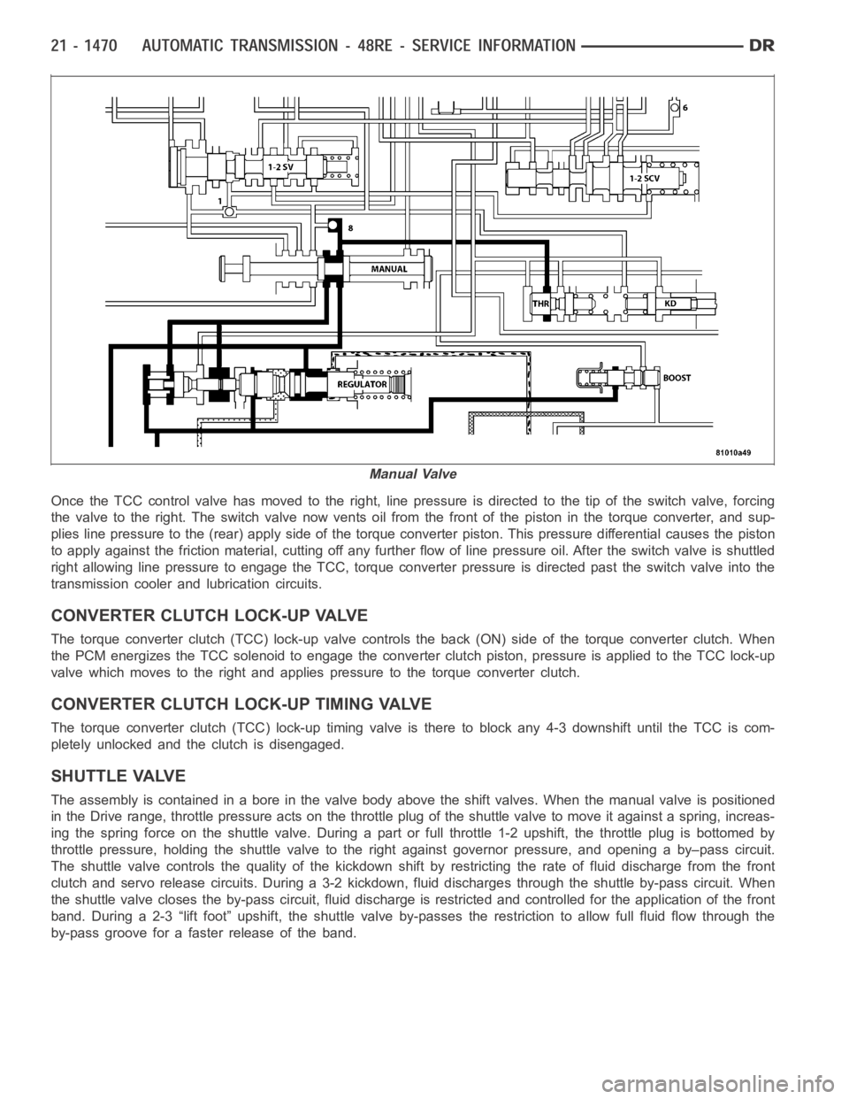
Once the TCC control valve has moved to the right, line pressure is directedto the tip of the switch valve, forcing
the valve to the right. The switch valve now vents oil from the front of the piston in the torque converter, and sup-
plies line pressure to the (rear) apply side of the torque converter piston. This pressure differential causes the piston
to apply against the friction material, cutting off any further flow of line pressure oil. After the switch valve is shuttled
right allowing line pressure to engage the TCC, torque converter pressureis directed past the switch valve into the
transmission cooler and lubrication circuits.
CONVERTER CLUTCH LOCK-UP VALVE
The torque converter clutch (TCC) lock-up valve controls the back (ON) side of the torque converter clutch. When
the PCM energizes the TCC solenoid to engage the converter clutch piston, pressure is applied to the TCC lock-up
valve which moves to the right and applies pressure to the torque converterclutch.
CONVERTER CLUTCH LOCK-UP TIMING VALVE
The torque converter clutch (TCC) lock-up timing valve is there to block any 4-3 downshift until the TCC is com-
pletely unlocked and the clutch is disengaged.
SHUTTLE VALVE
The assembly is contained in a bore in the valve body above the shift valves.When the manual valve is positioned
in the Drive range, throttle pressure acts on the throttle plug of the shuttle valve to move it against a spring, increas-
ing the spring force on the shuttle valve. During a part or full throttle 1-2upshift, the throttle plug is bottomed by
throttle pressure, holding the shuttle valve to the right against governor pressure, and opening a by–pass circuit.
The shuttle valve controls the quality of the kickdown shift by restricting the rate of fluid discharge from the front
clutch and servo release circuits. During a 3-2 kickdown, fluid discharges through the shuttle by-pass circuit. When
the shuttle valve closes the by-pass circuit, fluid discharge is restricted and controlled for the application of the front
band. During a 2-3 “lift foot” upshift, the shuttle valve by-passes the restriction to allow full fluid flow through the
by-pass groove for a faster release of the band.
Manual Valve