Page 4266 of 5267

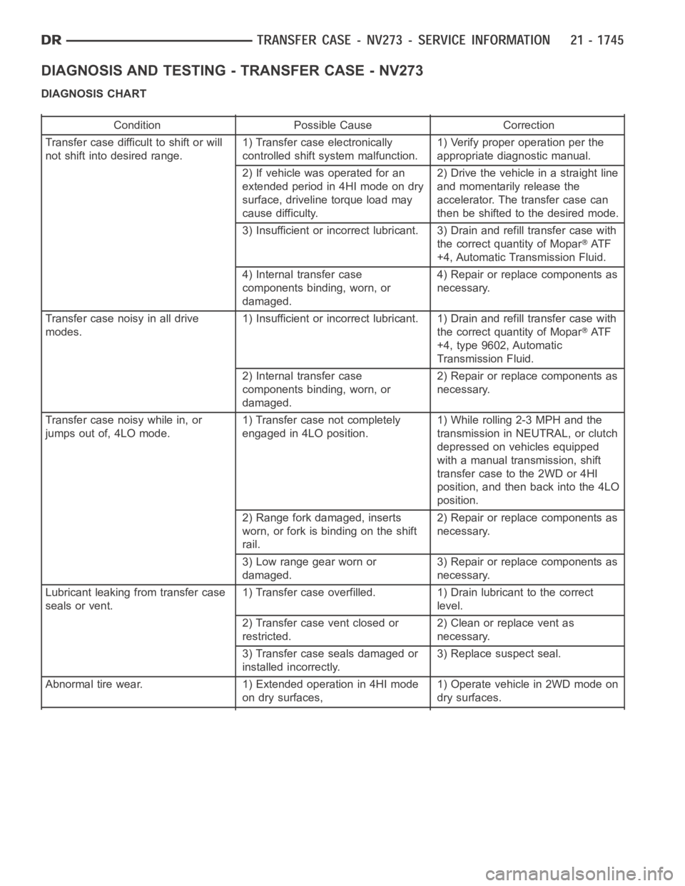
DIAGNOSIS AND TESTING - TRANSFER CASE - NV273
DIAGNOSIS CHART
Condition Possible Cause Correction
Transfer case difficult to shift or will
not shift into desired range.1) Transfer case electronically
controlled shift system malfunction.1) Verify proper operation per the
appropriate diagnostic manual.
2) If vehicle was operated for an
extended period in 4HI mode on dry
surface, driveline torque load may
cause difficulty.2) Drive the vehicle in a straight line
and momentarily release the
accelerator. The transfer case can
then be shifted to the desired mode.
3) Insufficient or incorrect lubricant. 3) Drain and refill transfer casewith
the correct quantity of Mopar
AT F
+4, Automatic Transmission Fluid.
4) Internal transfer case
components binding, worn, or
damaged.4) Repair or replace components as
necessary.
Transfer case noisy in all drive
modes.1) Insufficient or incorrect lubricant. 1) Drain and refill transfer casewith
the correct quantity of Mopar
AT F
+4, type 9602, Automatic
Transmission Fluid.
2) Internal transfer case
components binding, worn, or
damaged.2) Repair or replace components as
necessary.
Transfer case noisy while in, or
jumps out of, 4LO mode.1) Transfer case not completely
engaged in 4LO position.1) While rolling 2-3 MPH and the
transmission in NEUTRAL, or clutch
depressed on vehicles equipped
with a manual transmission, shift
transfer case to the 2WD or 4HI
position, and then back into the 4LO
position.
2) Range fork damaged, inserts
worn, or fork is binding on the shift
rail.2) Repair or replace components as
necessary.
3) Low range gear worn or
damaged.3) Repair or replace components as
necessary.
Lubricant leaking from transfer case
seals or vent.1) Transfer case overfilled. 1) Drain lubricant to the correct
level.
2) Transfer case vent closed or
restricted.2) Clean or replace vent as
necessary.
3) Transfer case seals damaged or
installed incorrectly.3) Replace suspect seal.
Abnormal tire wear. 1) Extended operation in 4HI mode
on dry surfaces,1) Operate vehicle in 2WD mode on
dry surfaces.
Page 4277 of 5267
11. Remove range fork (2) and hub (1) as an assem-
bly. Note fork position for installation reference.
12. Remove the shift sector (1).
MAINSHAFT
1. Remove the clutch gear (2) from the output shaft
(1).
Page 4293 of 5267
4. Install the mode hub (2) retaining ring (3) onto the
mainshaft (1).
5. Install the clutch gear (2) onto the output shaft (1).
Verify that the pointed ends of the clutch gear teeth
are pointing to the front of the mainshaft.
6. Lubricate sector shaft with transmission fluid and
install shift sector (1) in case. Position slot in sector
so it will be aligned with shift fork pin when shift
forks are installed.
7. Apply Loctite™ 242, or equivalent, to the threads of
the sector support to replenish the factory applied
patch. Install the shift sector support. Tighten the
sector support with Socket 9033 to 27-34 Nꞏm
(20-25 ft.lbs.).
Page 4658 of 5267

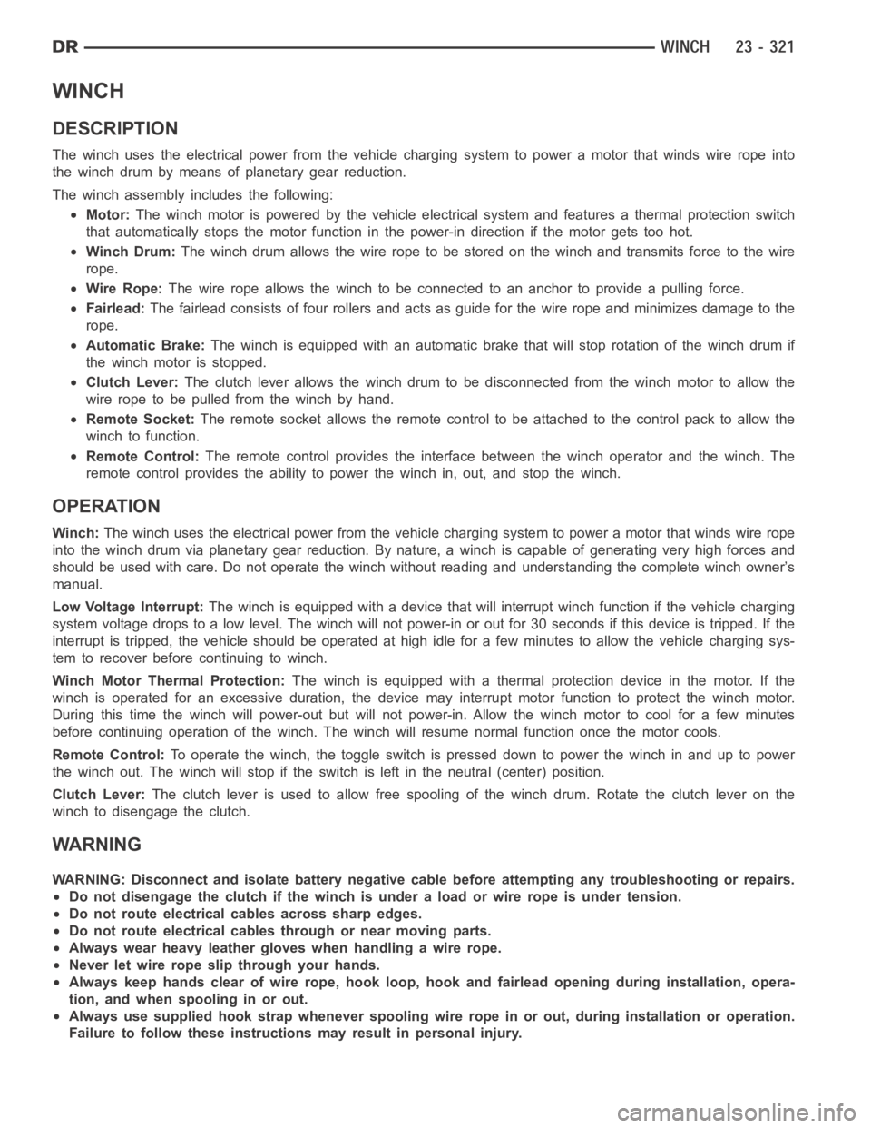
WINCH
DESCRIPTION
The winch uses the electrical power from the vehicle charging system to power a motor that winds wire rope into
the winch drum by means of planetary gear reduction.
The winch assembly includes the following:
Motor:The winch motor is powered by the vehicle electrical system and features a thermal protection switch
that automatically stops the motor function in the power-in direction if the motor gets too hot.
Winch Drum:The winch drum allows the wire rope to be stored on the winch and transmits forcetothewire
rope.
Wire Rope:The wire rope allows the winch to be connected to an anchor to provide a pulling force.
Fairlead:The fairlead consists of four rollers and acts as guide for the wire rope andminimizes damage to the
rope.
Automatic Brake:The winch is equipped with an automatic brake that will stop rotation of thewinch drum if
the winch motor is stopped.
Clutch Lever:The clutch lever allows the winch drum to be disconnected from the winch motor to allow the
wire rope to be pulled from the winch by hand.
Remote Socket:The remote socket allows the remote control to be attached to the control pack to allow the
winchtofunction.
Remote Control:The remote control provides the interface between the winch operator and the winch. The
remote control provides the ability to power the winch in, out, and stop thewinch.
OPERATION
Winch:The winch uses the electrical power from the vehicle charging system to power a motor that winds wire rope
into the winch drum via planetary gear reduction. By nature, a winch is capable of generating very high forces and
should be used with care. Do not operate the winch without reading and understanding the complete winch owner’s
manual.
Low Voltage Interrupt:The winch is equipped with a device that will interrupt winch function if the vehicle charging
system voltage drops to a low level. The winch will not power-in or out for 30seconds if this device is tripped. If the
interrupt is tripped, the vehicle should be operated at high idle for a few minutes to allow the vehicle charging sys-
tem to recover before continuing to winch.
Winch Motor Thermal Protection:The winch is equipped with athermalprotectiondeviceinthemotor.Ifthe
winch is operated for an excessive duration, the device may interrupt motor function to protect the winch motor.
During this time the winch will power-out but will not power-in. Allow the winch motor to cool for a few minutes
before continuing operation of the winch. The winch will resume normal function once the motor cools.
Remote Control:Tooperatethewinch,thetoggleswitchispresseddowntopowerthewinchinand up to power
the winch out. The winch will stop if the switch is left in the neutral (center) position.
Clutch Lever:The clutch lever is used to allow free spooling of the winch drum. Rotate theclutch lever on the
winch to disengage the clutch.
WARNING
WARNING: Disconnect and isolate battery negative cable before attempting any troubleshooting or repairs.
Do not disengage the clutch if the winch is under a load or wire rope is under tension.
Do not route electrical cables across sharp edges.
Do not route electrical cables through or near moving parts.
Always wear heavy leather gloves when handling a wire rope.
Never let wire rope slip through your hands.
Always keep hands clear of wire rope, hook loop, hook and fairlead opening during installation, opera-
tion, and when spooling in or out.
Always use supplied hook strap whenever spooling wire rope in or out, during installation or operation.
Failure to follow these instructions may result in personal injury.
Page 4659 of 5267

CAUTION: Do not leave the remote plugged into the winch when not in use. Leaving the remote plugged in,
may result in a dangerous condition and/or battery drain.
Always make sure the clutch is fully engaged or disengaged.
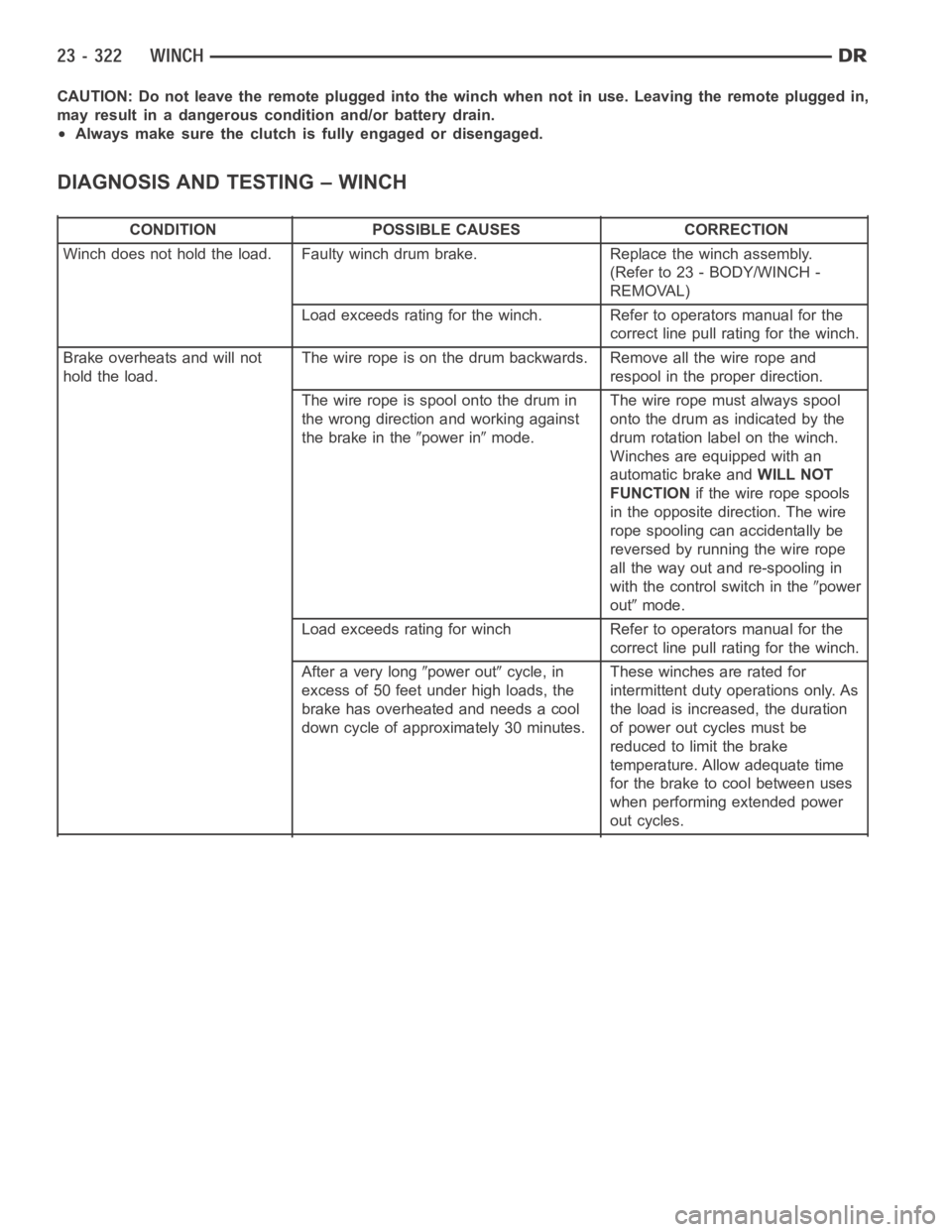
DIAGNOSIS AND TESTING – WINCH
CONDITION POSSIBLE CAUSES CORRECTION
Winch does not hold the load. Faulty winch drum brake. Replace the winch assembly.
(Refer to 23 - BODY/WINCH -
REMOVAL)
Load exceeds rating for the winch. Refer to operators manual for the
correct line pull rating for the winch.
Brake overheats and will not
hold the load.The wire rope is on the drum backwards. Remove all the wire rope and
respool in the proper direction.
Thewireropeisspoolontothedrumin
the wrong direction and working against
the brake in the
power inmode.The wire rope must always spool
onto the drum as indicated by the
drum rotation label on the winch.
Winches are equipped with an
automatic brake andWILL NOT
FUNCTIONif the wire rope spools
intheoppositedirection.Thewire
rope spooling can accidentally be
reversed by running the wire rope
all the way out and re-spooling in
with the control switch in the
power
out
mode.
Load exceeds rating for winch Refer to operators manual for the
correct line pull rating for the winch.
After a very long
power outcycle, in
excess of 50 feet under high loads, the
brake has overheated and needs a cool
down cycle of approximately 30 minutes.These winches are rated for
intermittent duty operations only. As
the load is increased, the duration
of power out cycles must be
reduced to limit the brake
temperature. Allow adequate time
for the brake to cool between uses
when performing extended power
out cycles.
Page 4660 of 5267

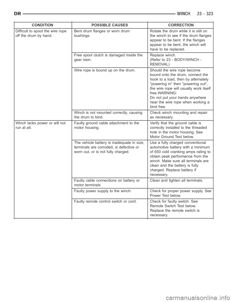
CONDITION POSSIBLE CAUSES CORRECTION
Difficult to spool the wire rope
off the drum by hand.Bent drum flanges or worn drum
bushings.Rotate the drum while it is still on
the winch to see if the drum flanges
appear to be bent. If the flanges
appear to be bent, the winch will
have to be replaced.
Free spool clutch is damaged inside the
gear train.Replace winch.
(Refer to 23 - BODY/WINCH -
REMOVAL)
Wire rope is bound up on the drum. Should the wire rope become
bound onto the drum, connect the
hook to a load, then by alternately
powering inthenpowering out,
the wire rope will usually work itself
free.WARNING:
Do not put your hands anywhere
near the wire rope when working a
bind free.
Winch is not mounted correctly, causing
the drum to bind.Check winch mounting and repair
as necessary.
Winch lacks power or will not
run at all.Faulty ground cable attachment to the
motor housing.Verify that the ground cable is
correctly installed to the threaded
hole in the motor housing. See
Motor Ground Test below.
The vehicle battery is inadequate in size,
terminals are corroded, is defective or
worn out, or is not fully charged.Use a fully charged conventional
automotive battery with a minimum
of650coldcrankingampsratingto
obtain peak performance from the
winch. Make sure all terminals are
clean and the battery is fully
charged. Replace battery if
necessary.
Faulty cable connections on battery or
motor terminalsClean and tighten all terminals.
Faulty power supply to the winch. Check for proper power supply. See
Power Test below.
Faulty remote control switch or cord. Check for faulty switch. See
Remote Switch Test below.
Replace the remote switch is
necessary.
Page 4679 of 5267
5. Stand winch assembly on the clutch end with the
motoruptomakeiteasiertoalignthemotorcou-
pler and drive shaft.
6. Remove the two motor mounting bolts (1) and
carefully lift the motor (2) off of the drum assembly.
INSTALLATION
1. With the winch assembly (1) standing on the clutch
side verify that the motor coupler (2) is centered in
the drive shaft opening (3).
Page 4692 of 5267
WIRE ROPE
REMOVAL
1. Move the clutch lever (2) to “Free Spool” and dis-
engage the wire rope. Pull out a portion to give it
some slack.
2. Remove the clip (2), pin (1) and remove the hook
(5) from the wire rope (4).
3. Pull the wire rope out and unwind the winch drum
(1).
4. Remove the bolt (2) and remove the rope (3).