Page 4015 of 5267
5. Slide tube brace (2) under tube and into alignment
with valve body screw holes.
6. Install and finger tighten three screws that secure
tube brace to valve body housings.
7. Bend tube brace tabs up and against tube to hold it
in position.
8. Tighten all valve body housing screws to 4 Nꞏm (35
in. lbs.) torque after tube and brace are installed.
Tighten screws in diagonal pattern starting at cen-
ter and working outward.
3-4 ACCUMULATOR
1. Position converter clutch valve (4) and 3-4 shift
valve (3) springs in housing.
2. Loosely attach accumulator housing (2) with right-
side screw (1). Install only one screw at this time
as accumulator must be free to pivot upward for
ease of installation.
3. Install 3-4 shift valve and spring (3).
Page 4016 of 5267

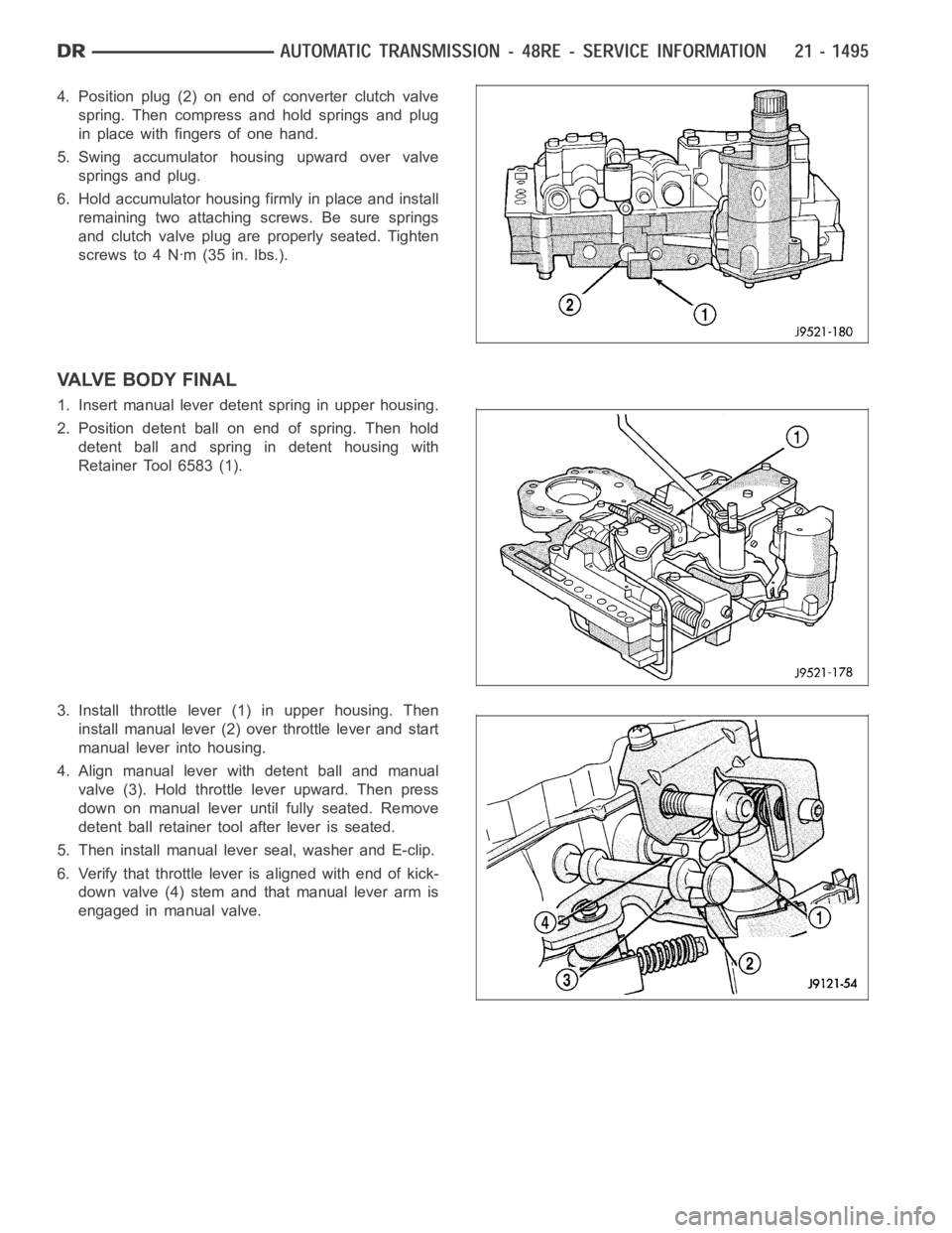
4. Position plug (2) on end of converter clutch valve
spring. Then compress and hold springs and plug
in place with fingers of one hand.
5. Swing accumulator housing upward over valve
springs and plug.
6. Hold accumulator housing firmly in place and install
remaining two attaching screws. Be sure springs
and clutch valve plug are properly seated. Tighten
screws to 4 Nꞏm (35 in. lbs.).
VALVE BODY FINAL
1. Insert manual lever detent spring in upper housing.
2. Position detent ball on end of spring. Then hold
detent ball and spring in detent housing with
Retainer Tool 6583 (1).
3. Install throttle lever (1) in upper housing. Then
install manual lever (2) over throttle lever and start
manual lever into housing.
4. Align manual lever with detent ball and manual
valve (3). Hold throttle lever upward. Then press
down on manual lever until fully seated. Remove
detent ball retainer tool after lever is seated.
5. Then install manual lever seal, washer and E-clip.
6. Verify that throttle lever is aligned with end of kick-
down valve (4) stem and that manual lever arm is
engaged in manual valve.
Page 4083 of 5267

TRANSFER CASE VERIFICATION TEST
1.
Disconnect all jumper wires and reconnect all previously disconnected components and connectors.
With the scan tool, select clear Stored DTCs.
Make sure that all accessories are turned off and that the battery is fully charged.
Test drive the vehicle in each Transfer Case range and verify proper operation in each range.
To select or deselect 2WD, AWD or 4HI mode, vehicle speed must be below 88 Kmh(55 mph) with all wheels
at vehicle speed.
Shifts will not take place with a wheel speed difference of greater than 21 Kmh (13 mph) between the front
and rear wheels.
To select or deselect 4LO (if equipped), vehicle speed must be below 5 Kmh (3mph) with the ignition ON and
the transmission in neutral (auto trans) or the clutch pedal pressed (man trans).
To select or deselect Transfer Case Neutral, vehicle speed must be 0 Kmh (0 mph) with the ignition ON,
engine OFF, the brake pedal applied, and the transmission in neutral (autotrans) or the clutch pedal pressed
(man trans). Press the Neutral button (if equipped) on the Transfer Case Selector Switch until the Neutral Indi-
cator is illuminated.
WARNING: Apply the parking brake. The vehicle may roll with the Transfer Case in neutral.
To verify that the Transfer Case is in Neutral, shift the automatic transmission into reverse and release the
brake pedal for three seconds or shift the manual transmission into gear andslowlyreleasetheclutchpedal.
There should be no vehicle movement if the Transfer Case is in Neutral.
With the scan tool, select View DTCs in the Totally Integrated Power Module(TIPM) and in the Instrument Cluster.
Are there any DTCs present in the Totally Integrated Power Module (TIPM) orin the Instrument Cluster?
Ye s>>
Return to the symptom list and perform the appropriate diagnostic test.
No>>
Repair is complete.
Page 4086 of 5267

A straight line shift pattern is used with a NEUTRAL detent. Lever range positions are imprinted in the shift knob.
SHIFTING
The transfer case can be shifted between the 2H and 4H operating ranges while the vehicle is in motion. The vehi-
cle must have the transmission placed in NEUTRAL, or the clutch depressed in the case of a manual transmission,
and be moving less than 2-3 MPH when shifting into and out of the 4L operatingrange.
DIAGNOSIS AND TESTING - TRANSFER CASE - NV241 GENII
Before beginning repair on a suspected transfer case malfunction, check all other driveline components beforehand.
The actual cause of a problem may be related to such items as: front hubs, axles, propeller shafts, wheels and tires,
transmission, or clutch instead. If all other driveline components are ingood condition and operating properly, refer
to the Diagnosis Chart for further information.
DIAGNOSIS CHART
Condition Possible Cause Correction
Transfer Case difficult to shift or will
not shift into desired range.1) Vehicle speed too great to permit
shifting.1) Stop vehicle and shift into
desired range. Or, reduce speed to
below 3-4 km/h (2-3 mph) before
attempting the shift.
2) If vehicle was operated for an
extended period in 4H on a dry
paved surface, the driveline torque
load may be causing a bind.2) Stop vehicle and shift the
transmission into neutral. Shift the
transfer case to 2H and operate
vehicle in 2H on dry paved
surfaces.
3) Transfer case external shift
linkage binding.3) Lubricate, repair, or replace
linkage bushings, or tighten loose
components as necessary.
4) Insufficient or incorrect lubricant. 4) Drain and refill to edge of fillhole
with Mopar
ATF +4, Automatic
Transmission fluid.
5) Internal components binding,
worn, or damaged.5) Disassemble the transfer case
and replace worn or damaged
components as necessary.
Transfer Case noisy in all operating
ranges.1) Insufficient or incorrect lubricant. 1) Drain and refill to edge of fillhole
with Mopar
ATF +4, Automatic
Transmission fluid.
Noisy in, or jumps out of, four wheel
drive low range.1) Transfer case not completely
engaged in 4L position.1) With the transmission in
NEUTRAL, or the clutch depressed
in the case of a manual
transmission and the vehicle moving
under 3-4 km/h (2-3 mph), shift the
transfer case to NEUTRAL and then
shift into the 4L position.
2) Shift linkage out of adjustment. 2) Adjust linkage.
3) Shift linkage loose or binding. 3) Tighten, lubricate, or repair
linkage as necessary.
4) Range fork damaged, inserts
worn, or fork is binding on the shift
rail.4) Disassemble unit and repair as
necessary.
5) Low range gear worn or
damaged.5) Disassemble unit and repair as
necessary.
Page 4096 of 5267
3. Remove drive sprocket (2) from the output shaft
(1).
4. Remove the clutch gear (2) from the output shaft
(1).
Remove the sprocket hub (2) from the output shaft
(1).
Page 4108 of 5267
5. Install the clutch gear (2) onto the output shaft (1).
6. Install the drive sprocket (2) onto the output shaft
(1).
7. Install the drive sprocket (3) thrust washer (2) onto
the output shaft (1).
Page 4128 of 5267

A straight line shift pattern is used with a NEUTRAL detent. Lever range positions are imprinted in the shift knob.
SHIFTING
The transfer case can be shifted between the 2H and 4H operating ranges while the vehicle is in motion. The vehi-
cle must have the transmission placed in NEUTRAL, or the clutch depressed in the case of a manual transmission,
and be moving less than 2-3 MPH when shifting into and out of the 4L operatingrange.
DIAGNOSIS AND TESTING - TRANSFER CASE - NV271
Before beginning repair on a suspected transfer case malfunction, check all other driveline components beforehand.
The actual cause of a problem may be related to such items as: front hubs, axles, propeller shafts, wheels and tires,
transmission, or clutch instead. If all other driveline components are ingood condition and operating properly, refer
to the Diagnosis Chart for further information.
DIAGNOSIS CHART
Condition Possible Cause Correction
Transfer Case difficult to shift or will
not shift into desired range.1) Vehicle speed too great to permit
shifting.1) Stop vehicle and shift into
desired range. Or, reduce speed to
below 3-4 km/h (2-3 mph) before
attempting the shift.
2) If vehicle was operated for an
extended period in 4H on a dry
paved surface, the driveline torque
load may be causing a bind.2) Stop vehicle and shift the
transmission into neutral. Shift the
transfer case to 2H and operate
vehicle in 2H on dry paved
surfaces.
3) Transfer case external shift
linkage binding.3) Lubricate, repair, or replace
linkage bushings, or tighten loose
components as necessary.
4) Insufficient or incorrect lubricant. 4) Drain and refill to edge of fillhole
with Mopar
ATF +4, Automatic
Transmission fluid.
5) Internal components binding,
worn, or damaged.5) Disassemble the transfer case
and replace worn or damaged
components as necessary.
Transfer Case noisy in all operating
ranges.1) Insufficient or incorrect lubricant. 1) Drain and refill to edge of fillhole
with Mopar
ATF +4, Automatic
Transmission fluid.
Noisy in, or jumps out of, four wheel
drive low range.1) Transfer case not completely
engaged in 4L position.1) With the transmission in
NEUTRAL, or the clutch depressed
in the case of a manual
transmission and the vehicle moving
under 3-4 km/h (2-3 mph), shift the
transfer case to NEUTRAL and then
shift into the 4L position.
2) Shift linkage out of adjustment. 2) Adjust linkage.
3) Shift linkage loose or binding. 3) Tighten, lubricate, or repair
linkage as necessary.
4) Range fork damaged, inserts
worn, or fork is binding on the shift
rail.4) Disassemble unit and repair as
necessary.
5) Low range gear worn or
damaged.5) Disassemble unit and repair as
necessary.
Page 4140 of 5267
13. Remove shift sector (1).
MAINSHAFT
1. Remove the clutch gear (2) from the output shaft
(1).
2. Remove the mode hub retaining ring (3) from the
mainshaft (1).