2006 DODGE RAM SRT-10 width
[x] Cancel search: widthPage 1692 of 5267
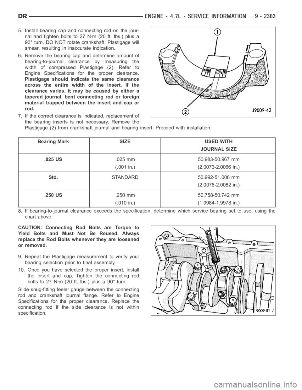
5. Install bearing cap and connecting rod on the jour-
nal and tighten bolts to 27 Nꞏm (20 ft. lbs.) plus a
90° turn. DO NOT rotate crankshaft. Plastigage will
smear, resulting in inaccurate indication.
6. Remove the bearing cap and determine amount of
bearing-to-journal clearance by measuring the
width of compressed Plastigage (2). Refer to
Engine Specifications for the proper clearance.
Plastigage should indicate the same clearance
across the entire width of the insert. If the
clearancevaries,itmaybecausedbyeithera
tapered journal, bent connecting rod or foreign
material trapped between the insert and cap or
rod.
7. If the correct clearance is indicated, replacement of
the bearing inserts is not necessary. Remove the
Plastigage (2) from crankshaft journal and bearing insert. Proceed with installation.
Bearing Mark SIZE USED WITH
JOURNAL SIZE
.025 US.025 mm 50.983-50.967 mm
(.001 in.) (2.0073-2.0066 in.)
Std.STANDARD 50.992-51.008 mm
(2.0076-2.0082 in.)
.250 US.250 mm 50.758-50.742 mm
(.010 in.) (1.9984-1.9978 in.)
8. If bearing-to-journal clearance exceeds the specification, determine which service bearing set to use, using the
chart above.
CAUTION: Connecting Rod Bolts are Torque to
Yield Bolts and Must Not Be Reused. Always
replace the Rod Bolts whenever they are loosened
or removed.
9. Repeat the Plastigage measurement to verify your
bearing selection prior to final assembly.
10. Once you have selected the proper insert, install
the insert and cap. Tighten the connecting rod
bolts to 27 Nꞏm (20 ft. lbs.) plus a 90° turn.
Slide snug-fitting feeler gauge between the connecting
rod and crankshaft journal flange. Refer to Engine
Specifications for the proper clearance. Replace the
connecting rod if the side clearance is not within
specification.
Page 1715 of 5267
MOUNT - FRONT
REMOVAL
2WD
1. Disconnect the negative cable from the battery.
CAUTION: Remove the viscous fan before raising engine. Failure to do so maycause damage to the fan
blade, fan clutch and fan shroud.
2. Remove the viscous fan (Refer to 7 - COOLING/ENGINE/FAN DRIVE VISCOUS CLUTCH - REMOVAL).
3. Raise the vehicle.
4. Remove the engine oil filter.
5. Remove the oil drain trough.
6. Support the engine with a suitable jack and a block of wood across the fullwidth of the engine oil pan.
7. Support the front axle with a suitable jack.
8. Remove the (4) bolts that attach the engine mounts to the front axle.
9. Remove the (3) bolts that attach the front axle to the left engine bracket.
10. Lower the front axle.
11. Remove the through bolts
12. Raise the engine far enough to be able to remove the left and right enginemounts.
13. Remove the (8) mount to engine attaching bolts
14. Remove the engine mounts.
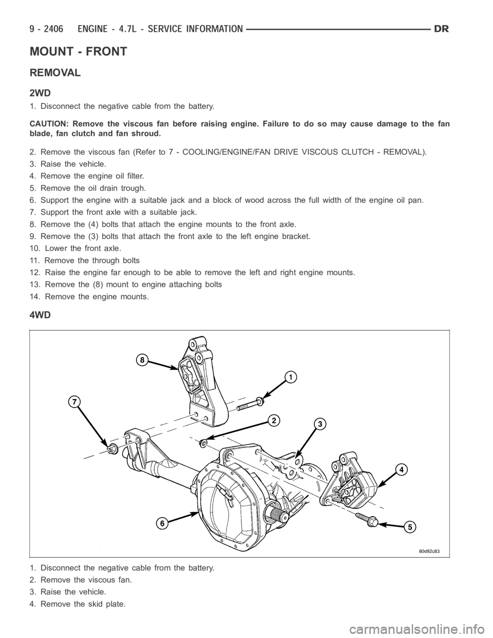
4WD
1. Disconnect the negative cable from the battery.
2. Remove the viscous fan.
3. Raise the vehicle.
4. Removetheskidplate.
Page 1716 of 5267
5. Remove the front crossmember.
6. Remove the engine oil filter.
7. Remove the oil drain trough.
8. Support the engine with a suitable jack and a block of wood across the fullwidth of the engine oil pan.
9. Support the front axle with a suitable jack.
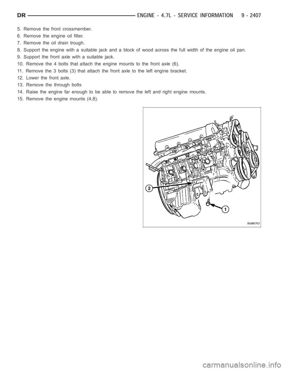
10. Remove the 4 bolts that attach the engine mounts to the front axle (6).
11. Remove the 3 bolts (3) that attach the front axle to the left engine bracket.
12. Lower the front axle.
13. Remove the through bolts
14. Raise the engine far enough to be able to remove the left and right enginemounts.
15. Remove the engine mounts (4,8).
Page 1777 of 5267
DESCRIPTION SPECIFICATION
Metric Standard
Cylinder Bore Diameter 99.50 mm 3.917 in.
Out of Round (MAX) 0.0076 mm 0003 in.
Taper (MAX) 0.0127 mm 0.0005 in.
Lifter Bore Diameter 21.45 - 21.425 mm 0.8444 - 0.8435 in.
PISTONS
DESCRIPTION SPECIFICATION
Metric Standard
Clearance 0.0215 - 0.0485 mm 0.0008 - 0.0019 in.
Measured at 38.0 mm ( 1.5 in.)
Below Deck
Ring Groove Diameter
Groove #1 89.6 - 89.8 mm 3.527 - 3.535 in.
Groove #2 88.1 - 88.3 mm 3.468 - 3.476 in.
Weight 414.5 grams 14.62 oz
Piston Length 54.70 - 55.30 2.153 - 2.177 in.
Ring Groove Width
No. 1 1.51 - 1.54 mm 0.0594 - 0.0606 in
No. 2 1.51 - 1.53 mm 0.0594 - 0.0602 in.
No. 3 3.030 - 3.055 mm 0.1192 - 0.1202 in.
PISTON PINS
DESCRIPTION SPECIFICATION
Metric Standard
Clearance In Piston 0.009 - 0.018 mm 0.00035 - 0.0007 in.
Diameter 24.0 - 24.003 mm 0.9448 - 0.9449 in.
Length 70.53 - 71.03 mm 2.78 - 2.80 in.
PISTON RINGS
DESCRIPTION SPECIFICATION
Metric Standard
Ring Gap
Top Compression Ring 0.23 - 0.38 mm 0.0090 - 0.0149 in.
Second Compression Ring 0.35 - 0.60 mm 0.0137 - 0.0236 in.
Oil Control (Steel Rails) 0.15 - 0.66 mm 0.0059 - 0.0259 in.
Side Clearance
Top Compression Ring .02 - .068 mm 0.0007 - 0.0026 in.
Second Compression Ring 0.02 - 0.058 mm 0.0007 - 0.0022 in.
Oil Ring (Steel Ring) .019 - .229 mm .0007 - .0091 in.
Ring Width
Page 1779 of 5267
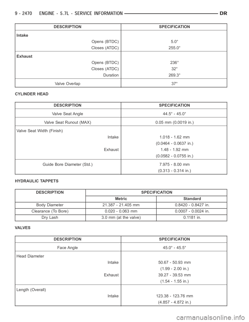
DESCRIPTION SPECIFICATION
Intake
Opens (BTDC) 5.0°
Closes (ATDC) 255.0°
Exhaust
Opens (BTDC) 236°
Closes (ATDC) 32°
Duration 269.3°
Va l v e O v e r l a p 3 7 °
CYLINDER HEAD
DESCRIPTION SPECIFICATION
Valve Seat Angle 44.5° - 45.0°
Valve Seat Runout (MAX) 0.05 mm (0.0019 in.)
Valve Seat Width (Finish)
Intake 1.018 - 1.62 mm
(0.0464 - 0.0637 in.)
Exhaust 1.48 - 1.92 mm
(0.0582 - 0.0755 in.)
Guide Bore Diameter (Std.) 7.975 - 8.00 mm
(0.313 - 0.314 in.)
HYDRAULIC TAPPETS
DESCRIPTION SPECIFICATION
Metric Standard
Body Diameter 21.387 - 21.405 mm 0.8420 - 0.8427 in.
Clearance (To Bore) 0.020 - 0.063 mm 0.0007 - 0.0024 in.
Dry Lash 3.0 mm (at the valve) 0.1181 in.
VA LV E S
DESCRIPTION SPECIFICATION
Face Angle 45.0° - 45.5°
Head Diameter
Intake 50.67 - 50.93 mm
(1.99 - 2.00 in.)
Exhaust 39.27 - 39.53 mm
(1.54 - 1.55 in.)
Length (Overall)
Intake 123.38 - 123.76 mm
(4.857 - 4.872 in.)
Page 1805 of 5267
VALVES & SEATS - INTAKE/EXHAUST
DESCRIPTION
DESCRIPTION - VALVE GUIDES
The valve guides are made of powdered metal and are pressed into the cylinder head. The guides are not replace-
able or serviceable, and valve guide reaming is not recommended. If the guides are worn beyond acceptable limits,
replace the cylinder heads.
DESCRIPTION
Both the intake and exhaust valves are made of steel. The intake valve is 50.93 mm (2.00 inches) in diameter and
the exhaust valve is 39.53 mm (1.55 inches) in diameter. All valves use three bead lock keepers to retain the
springs and promote valve rotation.
STANDARD PROCEDURE - REFACING
NOTE: Valve seats that are worn or burned can be reworked, provided that correct angle and seat width are
maintained. Otherwise the cylinder head must be replaced.
NOTE: When refacing valves and valve seats, it is important that the correct size valve guide pilot be used
for reseating stones. A true and complete surface must be obtained.
1. Using a suitable dial indicator measure the center of the valve seat Total run out must not exceed 0.051 mm
(0.002 in).
2. Apply a small amount of Prussian blue to the valve seat, insert the valve into the cylinder head, while applying
light pressure on the valve rotate the valve. Remove the valve and examine the valve face. If the blue is trans-
ferred below the top edge of the valve face, lower the valve seat using a 15 degree stone. If the blue is trans-
ferred to the bottom edge of the valve face, raise the valve seat using a 65 degree stone.
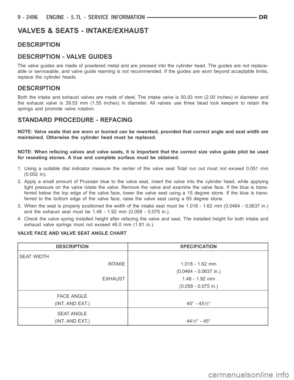
3. When the seat is properly positioned the width of the intake seat must be 1.018 - 1.62 mm (0.0464 - 0.0637 in.)
and the exhaust seat must be 1.48 - 1.92 mm (0.058 - 0.075 in.).
4. Check the valve spring installed height after refacing the valve and seat.Theinstalledheightforbothintakeand
exhaust valve springs must not exceed 46.0 mm (1.81 in.).
VALVE FACE AND VALVE SEAT ANGLE CHART
DESCRIPTION SPECIFICATION
SEAT WIDTH
INTAKE 1.018 - 1.62 mm
(0.0464 - 0.0637 in.)
EXHAUST 1.48 - 1.92 mm
(0.058 - 0.075 in.)
FA C E A N G L E
(INT. AND EXT.) 45° - 45
1⁄2°
SEAT ANGLE
(INT. AND EXT.) 44
1⁄2° - 45°
Page 1912 of 5267
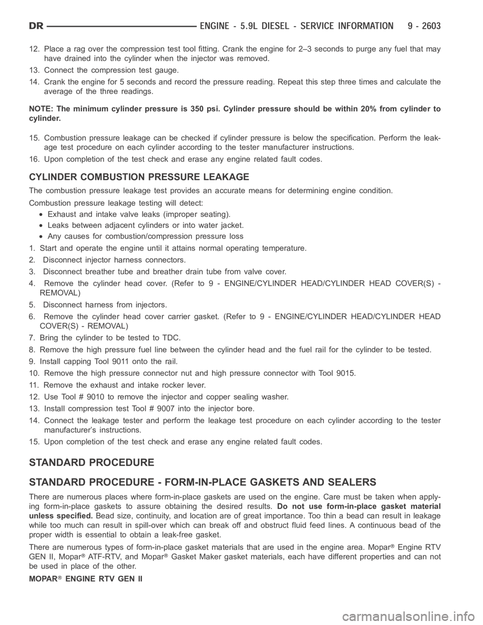
12. Place a rag over the compression test tool fitting. Crank the engine for2–3 seconds to purge any fuel that may
have drained into the cylinder when the injector was removed.
13. Connect the compression test gauge.
14. Crank the engine for 5 seconds and record the pressure reading. Repeat this step three times and calculate the
average of the three readings.
NOTE: The minimum cylinder pressure is 350 psi. Cylinder pressure should be within 20% from cylinder to
cylinder.
15. Combustion pressure leakage can be checked if cylinder pressure is below the specification. Perform the leak-
age test procedure on each cylinder according to the tester manufacturer instructions.
16. Upon completion of the test check and erase any engine related fault codes.
CYLINDER COMBUSTION PRESSURE LEAKAGE
The combustion pressure leakage test provides an accurate means for determining engine condition.
Combustion pressure leakage testing will detect:
Exhaust and intake valve leaks (improper seating).
Leaks between adjacent cylinders or into water jacket.
Any causes for combustion/compression pressure loss
1. Start and operate the engine until it attains normal operating temperature.
2. Disconnect injector harness connectors.
3. Disconnect breather tube and breather drain tube from valve cover.
4. Remove the cylinder head cover. (Refer to 9 - ENGINE/CYLINDER HEAD/CYLINDER HEAD COVER(S) -
REMOVAL)
5. Disconnect harness from injectors.
6. Remove the cylinder head cover carrier gasket. (Refer to 9 - ENGINE/CYLINDER HEAD/CYLINDER HEAD
COVER(S) - REMOVAL)
7. BringthecylindertobetestedtoTDC.
8. Remove the high pressure fuel line between the cylinder head and the fuelrail for the cylinder to be tested.
9. Install capping Tool 9011 onto the rail.
10. Remove the high pressure connector nut and high pressure connector with Tool 9015.
11. Remove the exhaust and intake rocker lever.
12. Use Tool # 9010 to remove the injector and copper sealing washer.
13. Install compression test Tool # 9007 into the injector bore.
14. Connect the leakage tester and perform the leakage test procedure on each cylinder according to the tester
manufacturer’s instructions.
15. Upon completion of the test check and erase any engine related fault codes.
STANDARD PROCEDURE
STANDARD PROCEDURE - FORM-IN-PLACE GASKETS AND SEALERS
There are numerous places where form-in-place gaskets are used on the engine. Care must be taken when apply-
ing form-in-place gaskets to assure obtaining the desired results.Do not use form-in-place gasket material
unless specified.Bead size, continuity, and location are of great importance. Too thin a bead can result in leakage
while too much can result in spill-overwhich can break off and obstruct fluid feed lines. A continuous bead of the
proper width is essential to obtain a leak-free gasket.
There are numerous types of form-in-place gasket materials that are used in the engine area. Mopar
Engine RTV
GEN II, Mopar
ATF-RTV, and MoparGasket Maker gasket materials, each have different properties and can not
be used in place of the other.
MOPAR
ENGINE RTV GEN II
Page 2031 of 5267
STANDARD PROCEDURE
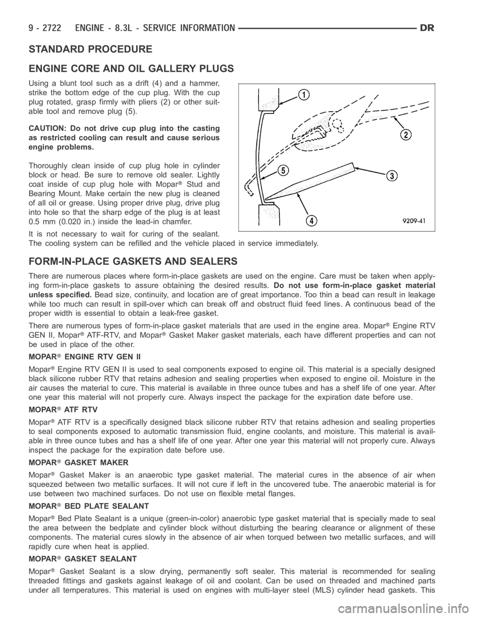
ENGINE CORE AND OIL GALLERY PLUGS
Using a blunt tool such as a drift (4) and a hammer,
strike the bottom edge of the cup plug. With the cup
plug rotated, grasp firmly with pliers (2) or other suit-
able tool and remove plug (5).
CAUTION: Do not drive cup plug into the casting
as restricted cooling can result and cause serious
engine problems.
Thoroughly clean inside of cup plug hole in cylinder
block or head. Be sure to remove old sealer. Lightly
coat inside of cup plug hole with Mopar
Stud and
Bearing Mount. Make certain the new plug is cleaned
of all oil or grease. Using proper drive plug, drive plug
into hole so that the sharp edge of the plug is at least
0.5 mm (0.020 in.) inside the lead-in chamfer.
It is not necessary to wait for curing of the sealant.
The cooling system can be refilled and the vehicle placed in service immediately.
FORM-IN-PLACE GASKETS AND SEALERS
There are numerous places where form-in-place gaskets are used on the engine. Care must be taken when apply-
ing form-in-place gaskets to assure obtaining the desired results.Do not use form-in-place gasket material
unless specified.Bead size, continuity, and location are of great importance. Too thin a bead can result in leakage
while too much can result in spill-overwhich can break off and obstruct fluid feed lines. A continuous bead of the
proper width is essential to obtain a leak-free gasket.
There are numerous types of form-in-place gasket materials that are used in the engine area. Mopar
Engine RTV
GEN II, Mopar
ATF-RTV, and MoparGasket Maker gasket materials, each have different properties and can not
be used in place of the other.
MOPAR
ENGINE RTV GEN II
Mopar
Engine RTV GEN II is used to seal components exposed to engine oil. This material is a specially designed
black silicone rubber RTV that retains adhesion and sealing properties when exposed to engine oil. Moisture in the
air causes the material to cure. This material is available in three ounce tubes and has a shelf life of one year. After
one year this material will not properly cure. Always inspect the package for the expiration date before use.
MOPAR
AT F R T V
Mopar
ATF RTV is a specifically designed black silicone rubber RTV that retains adhesion and sealing properties
to seal components exposed to automatic transmission fluid, engine coolants, and moisture. This material is avail-
able in three ounce tubes and has a shelf life of one year. After one year thismaterial will not properly cure. Always
inspect the package for the expiration date before use.
MOPAR
GASKET MAKER
Mopar
Gasket Maker is an anaerobic type gasket material. The material cures in the absence of air when
squeezed between two metallic surfaces. It will not cure if left in the uncovered tube. The anaerobic material is for
use between two machined surfaces. Do not use on flexible metal flanges.
MOPAR
BED PLATE SEALANT
Mopar
Bed Plate Sealant is a unique (green-in-color) anaerobic type gasket material that is specially made to seal
the area between the bedplate and cylinder block without disturbing the bearing clearance or alignment of these
components. The material cures slowly in the absence of air when torqued between two metallic surfaces, and will
rapidly cure when heat is applied.
MOPAR
GASKET SEALANT
Mopar
Gasket Sealant is a slow drying, permanently soft sealer. This material isrecommended for sealing
threaded fittings and gaskets against leakage of oil and coolant. Can be used on threaded and machined parts
under all temperatures. This material is used on engines with multi-layersteel (MLS) cylinder head gaskets. This