2006 DODGE RAM SRT-10 width
[x] Cancel search: widthPage 2042 of 5267
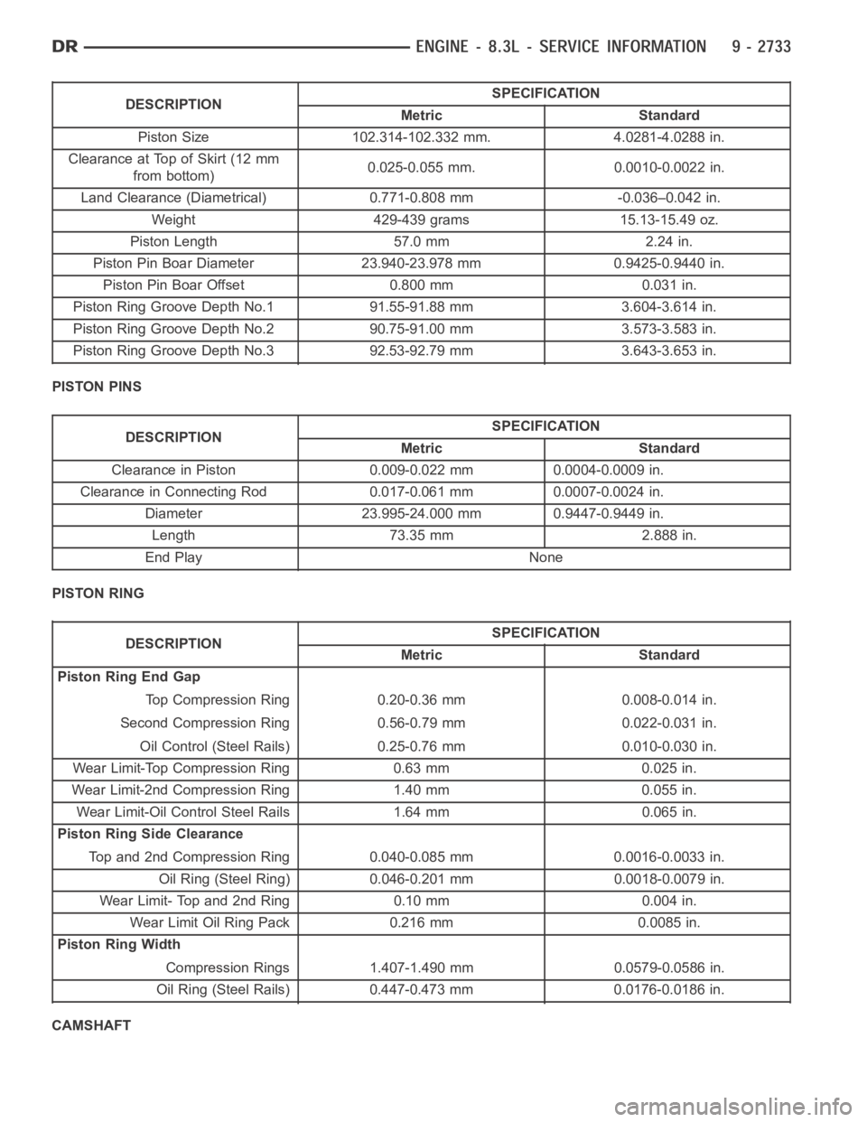
DESCRIPTIONSPECIFICATION
Metric Standard
Piston Size 102.314-102.332 mm. 4.0281-4.0288 in.
Clearance at Top of Skirt (12 mm
from bottom)0.025-0.055 mm. 0.0010-0.0022 in.
Land Clearance (Diametrical) 0.771-0.808 mm -0.036–0.042 in.
Weight 429-439 grams 15.13-15.49 oz.
Piston Length 57.0 mm 2.24 in.
Piston Pin Boar Diameter 23.940-23.978 mm 0.9425-0.9440 in.
Piston Pin Boar Offset 0.800 mm 0.031 in.
Piston Ring Groove Depth No.1 91.55-91.88 mm 3.604-3.614 in.
Piston Ring Groove Depth No.2 90.75-91.00 mm 3.573-3.583 in.
Piston Ring Groove Depth No.3 92.53-92.79 mm 3.643-3.653 in.
PISTON PINS
DESCRIPTIONSPECIFICATION
Metric Standard
Clearance in Piston 0.009-0.022 mm 0.0004-0.0009 in.
Clearance in Connecting Rod 0.017-0.061 mm 0.0007-0.0024 in.
Diameter 23.995-24.000 mm 0.9447-0.9449 in.
Length 73.35 mm 2.888 in.
End Play None
PISTON RING
DESCRIPTIONSPECIFICATION
Metric Standard
Piston Ring End Gap
Top Compression Ring 0.20-0.36 mm 0.008-0.014 in.
Second Compression Ring 0.56-0.79 mm 0.022-0.031 in.
Oil Control (Steel Rails) 0.25-0.76 mm 0.010-0.030 in.
Wear Limit-Top Compression Ring 0.63 mm 0.025 in.
Wear Limit-2nd Compression Ring 1.40 mm 0.055 in.
Wear Limit-Oil Control Steel Rails 1.64 mm 0.065 in.
Piston Ring Side Clearance
Top and 2nd Compression Ring 0.040-0.085 mm 0.0016-0.0033 in.
Oil Ring (Steel Ring) 0.046-0.201 mm 0.0018-0.0079 in.
Wear Limit- Top and 2nd Ring 0.10 mm 0.004 in.
Wear Limit Oil Ring Pack 0.216 mm 0.0085 in.
Piston Ring Width
Compression Rings 1.407-1.490 mm 0.0579-0.0586 in.
Oil Ring (Steel Rails) 0.447-0.473 mm 0.0176-0.0186 in.
CAMSHAFT
Page 2043 of 5267
DESCRIPTIONSPECIFICATION
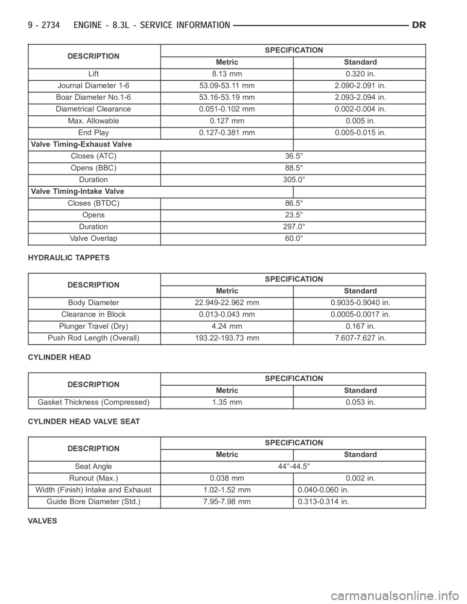
Metric Standard
Lift 8.13 mm 0.320 in.
Journal Diameter 1-6 53.09-53.11 mm 2.090-2.091 in.
Boar Diameter No.1-6 53.16-53.19 mm 2.093-2.094 in.
Diametrical Clearance 0.051-0.102 mm 0.002-0.004 in.
Max. Allowable 0.127 mm 0.005 in.
End Play 0.127-0.381 mm 0.005-0.015 in.
Valve Timing-Exhaust Valve
Closes (ATC) 36.5°
Opens (BBC) 88.5°
Duration 305.0°
Valve Timing-Intake Valve
Closes (BTDC) 86.5°
Opens 23.5°
Duration 297.0°
Valve Overlap 60.0°
HYDRAULIC TAPPETS
DESCRIPTIONSPECIFICATION
Metric Standard
Body Diameter 22.949-22.962 mm 0.9035-0.9040 in.
Clearance in Block 0.013-0.043 mm 0.0005-0.0017 in.
Plunger Travel (Dry) 4.24 mm 0.167 in.
Push Rod Length (Overall) 193.22-193.73 mm 7.607-7.627 in.
CYLINDER HEAD
DESCRIPTIONSPECIFICATION
Metric Standard
Gasket Thickness (Compressed) 1.35 mm 0.053 in.
CYLINDER HEAD VALVE SEAT
DESCRIPTIONSPECIFICATION
Metric Standard
Seat Angle 44°-44.5°
Runout (Max.) 0.038 mm 0.002 in.
Width (Finish) Intake and Exhaust 1.02-1.52 mm 0.040-0.060 in.
Guide Bore Diameter (Std.) 7.95-7.98 mm 0.313-0.314 in.
VA LV E S
Page 2075 of 5267
INTAKE/EXHAUST - VALVES/SEATS/GUIDES
STANDARD PROCEDURE - VALVE AND VALVE SEAT - REFACING
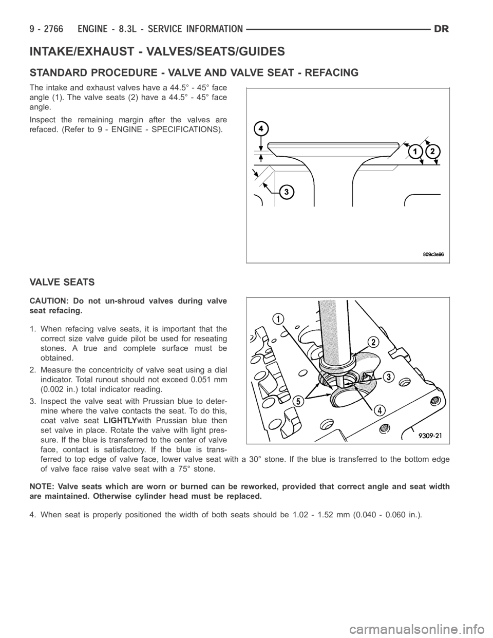
The intake and exhaust valves have a 44.5° - 45° face
angle (1). The valve seats (2) have a 44.5° - 45° face
angle.
Inspect the remaining margin after the valves are
refaced. (Refer to 9 - ENGINE - SPECIFICATIONS).
VALVE SEATS
CAUTION: Do not un-shroud valves during valve
seat refacing.
1. When refacing valve seats, it is important that the
correct size valve guide pilot be used for reseating
stones. A true and complete surface must be
obtained.
2. Measure the concentricity of valve seat using a dial
indicator. Total runout should not exceed 0.051 mm
(0.002 in.) total indicator reading.
3. Inspect the valve seat with Prussian blue to deter-
mine where the valve contacts the seat. To do this,
coat valve seatLIGHTLYwith Prussian blue then
set valve in place. Rotate the valve with light pres-
sure. If the blue is transferred to the center of valve
face, contact is satisfactory. If the blue is trans-
ferred to top edge of valve face, lower valve seat with a 30° stone. If the blue is transferred to the bottom edge
of valve face raise valve seat with a 75° stone.
NOTE: Valve seats which are worn or burned can be reworked, provided that correct angle and seat width
are maintained. Otherwise cylinder head must be replaced.
4. When seat is properly positioned the width of both seats should be 1.02 - 1.52 mm (0.040 - 0.060 in.).
Page 2119 of 5267
BEARINGS-CONNECTING ROD
DESCRIPTION
The bearing caps are not interchangeable and should be paint marked or scribed at removal to insure correct
assembly.
The bearing shells must be installed so that the tangs are in the machined grooves in the rods and caps.
Limits of taper or out-of-round on any crankshaft journals should be held to 0.013 mm (0.0005 in.). Bearings are
available in 0.025 mm (0.001 in.), 0.051 mm (0.002 in.), 0.076 mm (0.003 in.), 0.254 mm (0.010 in.) and 0.305 mm
(0.012 in.) undersize.Install the bearings in pairs. Do not use a new bearing half with an old bearing half. Do
not file the rods or bearing caps.
STANDARD PROCEDURE
CONNECTING ROD BEARING - FITTING
Fit all rods on one bank until complete. Do not alternate from one bank to another, because when the rods are
assembled to pistons correctly, they are not interchangeable from one bank to another.
The bearing caps are not interchangeable and should be marked at removal toinsure correct assembly.
The bearing shells must be installed so that the tangs are in the machined grooves in the rods and caps.
Limits of taper or out-of-round on any crankshaft journals should be held to 0.013 mm (0.0005 in.). Bearings are
available in 0.025 mm (0.001 in.), 0.051 mm (0.002 in.), 0.076 mm (0.003 in.), 0.254 mm (0.010 in.) and 0.305 mm
(0.012 in.) undersize.Install the bearings in pairs. Do not use a new bearing half with an old bearing half. Do
not file the rods or bearing caps.
1. (Refer to 9 - ENGINE/ENGINE BLOCK/CONNECTING ROD BEARINGS - STANDARD PROCEDURE) - Mea-
suring Connecting Rod Bearing Clearance to determine bearing clearance.
2. Before installing the connecting rod cap bolts, the bolt threads shouldbe oiled with engine oil.
3. Install bolts finger tight, then alternately torque each bolt to assemble the cap properly.
4. Tighten the connecting rod bolts to 68 Nꞏm (50 ft. lbs.).
MEASURING CONNECTING ROD BEARING CLEARANCE
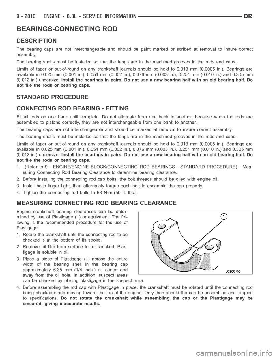
Engine crankshaft bearing clearances can be deter-
mined by use of Plastigage (1) or equivalent. The fol-
lowing is the recommended procedure for the use of
Plastigage:
1. Rotate the crankshaft until the connecting rod to be
checked is at the bottom of its stroke.
2. Remove oil film from surface to be checked. Plas-
tigage is soluble in oil.
3. Place a piece of Plastigage (1) across the entire
width of the bearing shell in the bearing cap
approximately 6.35 mm (1/4 inch.) off center and
away from the oil hole. In addition, suspect areas
can be checked by placing plastigage in the suspect area.
4. Before assembling the rod cap with Plastigage in place, the crankshaft must be rotated until the connecting rod
being checked starts moving toward the top of the engine. Only then should the cap be assembled and torqued
to specifications.Do not rotate the crankshaft while assembling the cap or the Plastigage maybe
smeared, giving inaccurate results.
Page 2120 of 5267
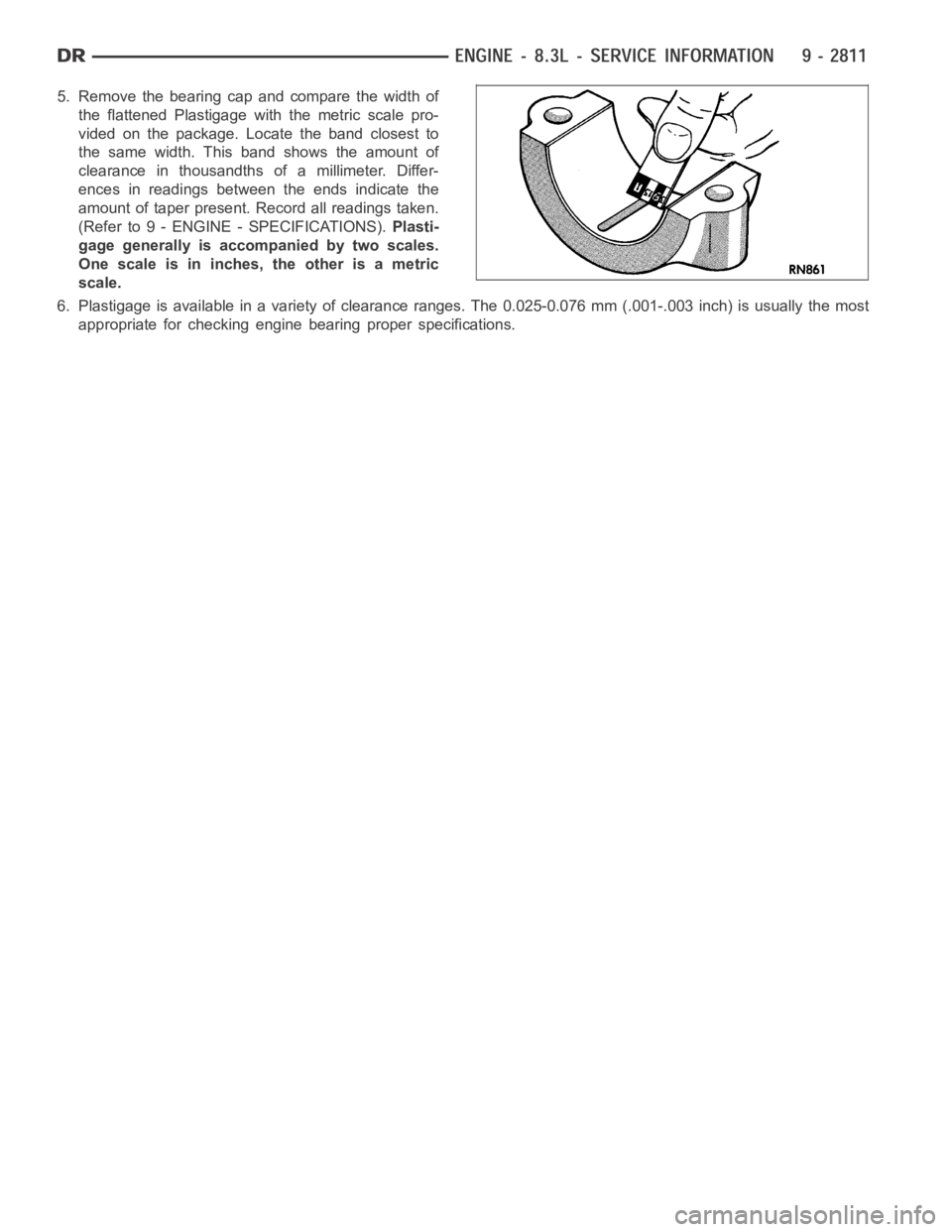
5. Remove the bearing cap and compare the width of
the flattened Plastigage with the metric scale pro-
vided on the package. Locate the band closest to
the same width. This band shows the amount of
clearance in thousandths of a millimeter. Differ-
ences in readings between the ends indicate the
amount of taper present. Record all readings taken.
(Refer to 9 - ENGINE - SPECIFICATIONS).Plasti-
gage generally is accompanied by two scales.
One scale is in inches, the other is a metric
scale.
6. Plastigage is available in a variety of clearance ranges. The 0.025-0.076 mm (.001-.003 inch) is usually the most
appropriate for checking engine bearing proper specifications.
Page 2127 of 5267
ALTERNATIVE METHOD
1. With the weight of the crankshaft being supported
by a jack under the counterweight adjacent to the
bearing being checked.
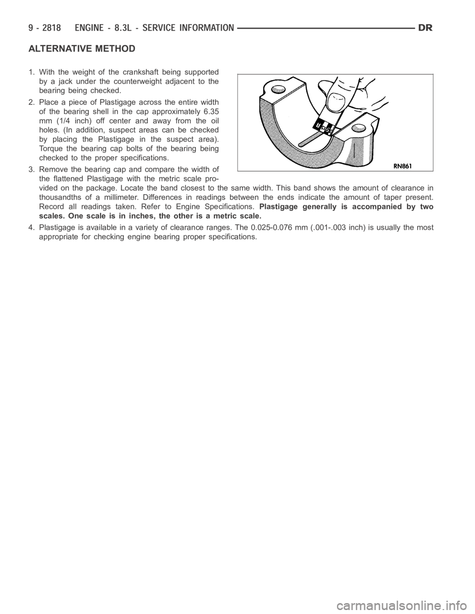
2. Place a piece of Plastigage across the entire width
of the bearing shell in the cap approximately 6.35
mm (1/4 inch) off center and away from the oil
holes. (In addition, suspect areas can be checked
by placing the Plastigage in the suspect area).
Torque the bearing cap bolts of the bearing being
checked to the proper specifications.
3. Remove the bearing cap and compare the width of
the flattened Plastigage with the metric scale pro-
vided on the package. Locate the band closest to the same width. This band shows the amount of clearance in
thousandths of a millimeter. Differences in readings between the ends indicate the amount of taper present.
Record all readings taken. Refer to Engine Specifications.Plastigage generally is accompanied by two
scales. One scale is in inches, the other is a metric scale.
4. Plastigage is available in a variety of clearance ranges. The 0.025-0.076 mm (.001-.003 inch) is usually the most
appropriate for checking engine bearing proper specifications.
Page 2162 of 5267
OPERATION
Exhaust gas pressure and energy drive the turbine,
which in turn drives a centrifugal compressor that
compresses the inlet air, and forces the air into the
engine through the charge air cooler and plumbing.
Since heat is a by-product of this compression, the air
must pass through a charge air cooler to cool the
incoming air and maintain power and efficiency.
Increasing air flow to the engine provides:
Improved engine performance
Lower exhaust smoke density
Improved operating economy
Altitude compensation
Noise reduction.
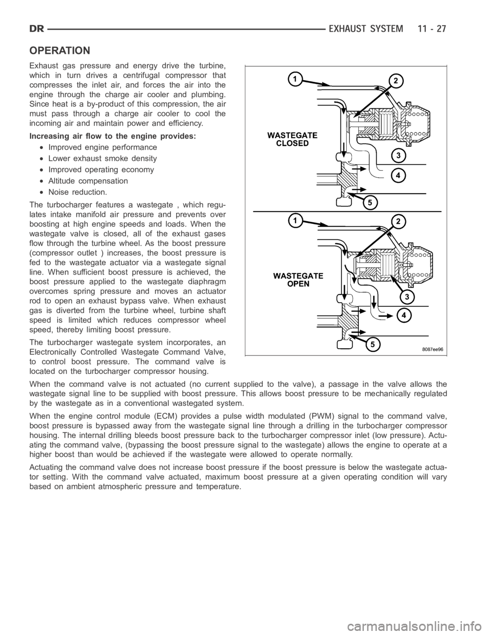
The turbocharger features a wastegate , which regu-
lates intake manifold air pressure and prevents over
boosting at high engine speeds and loads. When the
wastegate valve is closed, all of the exhaust gases
flow through the turbine wheel. As the boost pressure
(compressor outlet ) increases, the boost pressure is
fed to the wastegate actuator via a wastegate signal
line. When sufficient boost pressure is achieved, the
boost pressure applied to the wastegate diaphragm
overcomes spring pressure and moves an actuator
rod to open an exhaust bypass valve. When exhaust
gas is diverted from the turbine wheel, turbine shaft
speed is limited which reduces compressor wheel
speed, thereby limiting boost pressure.
The turbocharger wastegate system incorporates, an
Electronically Controlled Wastegate Command Valve,
to control boost pressure. The command valve is
located on the turbocharger compressor housing.
When the command valve is not actuated (no current supplied to the valve), apassage in the valve allows the
wastegate signal line to be supplied with boost pressure. This allows boost pressure to be mechanically regulated
by the wastegate as in a conventional wastegated system.
When the engine control module (ECM) provides a pulse width modulated (PWM) signal to the command valve,
boost pressure is bypassed away from the wastegate signal line through a drilling in the turbocharger compressor
housing. The internal drilling bleeds boost pressure back to the turbocharger compressor inlet (low pressure). Actu-
ating the command valve, (bypassing the boost pressure signal to the wastegate) allows the engine to operate at a
higher boost than would be achieved if the wastegate were allowed to operate normally.
Actuating the command valve does not increase boost pressure if the boost pressure is below the wastegate actua-
tor setting. With the command valve actuated, maximum boost pressure at a given operating condition will vary
based on ambient atmospheric pressure and temperature.
Page 2293 of 5267
INJECTOR - FUEL
DESCRIPTION
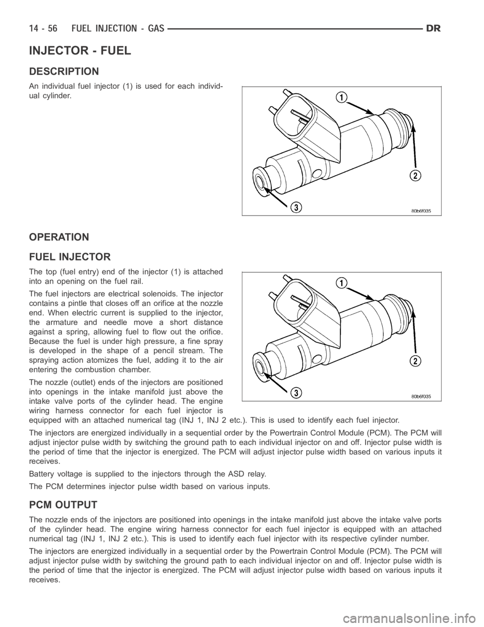
An individual fuel injector (1) is used for each individ-
ual cylinder.
OPERATION
FUEL INJECTOR
The top (fuel entry) end of the injector (1) is attached
into an opening on the fuel rail.
The fuel injectors are electrical solenoids. The injector
contains a pintle that closes off an orifice at the nozzle
end. When electric current is supplied to the injector,
the armature and needle move a short distance
against a spring, allowing fuel to flow out the orifice.
Because the fuel is under high pressure, a fine spray
is developed in the shape of a pencil stream. The
spraying action atomizes the fuel, adding it to the air
entering the combustion chamber.
The nozzle (outlet) ends of the injectors are positioned
into openings in the intake manifold just above the
intake valve ports of the cylinder head. The engine
wiring harness connector for each fuel injector is
equipped with an attached numerical tag (INJ 1, INJ 2 etc.). This is used to identify each fuel injector.
The injectors are energized individually in a sequential order by the Powertrain Control Module (PCM). The PCM will
adjust injector pulse width by switching the ground path to each individual injector on and off. Injector pulse width is
the period of time that the injector isenergized. The PCM will adjust injector pulse width based on various inputs it
receives.
Battery voltage is supplied to the injectors through the ASD relay.
The PCM determines injector pulse width based on various inputs.
PCM OUTPUT
The nozzle ends of the injectors are positioned into openings in the intakemanifold just above the intake valve ports
of the cylinder head. The engine wiring harness connector for each fuel injector is equipped with an attached
numerical tag (INJ 1, INJ 2 etc.). This is used to identify each fuel injector with its respective cylinder number.
The injectors are energized individually in a sequential order by the Powertrain Control Module (PCM). The PCM will
adjust injector pulse width by switching the ground path to each individual injector on and off. Injector pulse width is
the period of time that the injector isenergized. The PCM will adjust injector pulse width based on various inputs it
receives.