2006 DODGE RAM SRT-10 width
[x] Cancel search: widthPage 1505 of 5267
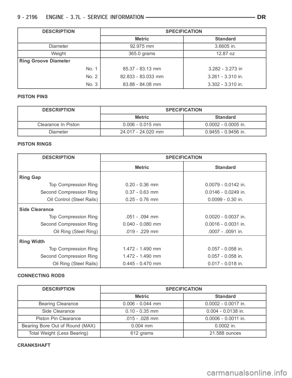
DESCRIPTION SPECIFICATION
Metric Standard
Diameter 92.975 mm 3.6605 in.
Weight 365.0 grams 12.87 oz
Ring Groove Diameter
No. 1 85.37 - 83.13 mm 3.282 - 3.273 in
No. 2 82.833 - 83.033 mm 3.261 - 3.310 in.
No. 3 83.88 - 84.08 mm 3.302 - 3.310 in.
PISTON PINS
DESCRIPTION SPECIFICATION
Metric Standard
Clearance In Piston 0.006 - 0.015 mm 0.0002 - 0.0005 in.
Diameter 24.017 - 24.020 mm 0.9455 - 0.9456 in.
PISTON RINGS
DESCRIPTION SPECIFICATION
Metric Standard
Ring Gap
Top Compression Ring 0.20 - 0.36 mm 0.0079 - 0.0142 in.
Second Compression Ring 0.37 - 0.63 mm 0.0146 - 0.0249 in.
Oil Control (Steel Rails) 0.25 - 0.76 mm 0.0099 - 0.30 in.
Side Clearance
Top Compression Ring .051 - .094 mm 0.0020 - 0.0037 in.
Second Compression Ring 0.040 - 0.080 mm 0.0016 - 0.0031 in.
Oil Ring (Steel Ring) .019 - .229 mm .0007 - .0091 in.
Ring Width
Top Compression Ring 1.472 - 1.490 mm 0.057 - 0.058 in.
Second Compression Ring 1.472 - 1.490 mm 0.057 - 0.058 in.
Oil Ring (Steel Rails) 0.445 - 0.470 mm 0.017 - 0.018 in.
CONNECTING RODS
DESCRIPTION SPECIFICATION
Metric Standard
Bearing Clearance 0.006 - 0.044 mm 0.0002 - 0.0017 in.
Side Clearance 0.10 - 0.35 mm 0.004 - 0.0138 in.
Piston Pin Clearance .015 - .028 mm 0.0006 - 0.0011 in.
Bearing Bore Out of Round (MAX) 0.004 mm 0.0002 in.
Total Weight (Less Bearing) 612 grams 21.588 ounces
CRANKSHAFT
Page 1528 of 5267
VALVES & SEATS - INTAKE/EXHAUST
DESCRIPTION
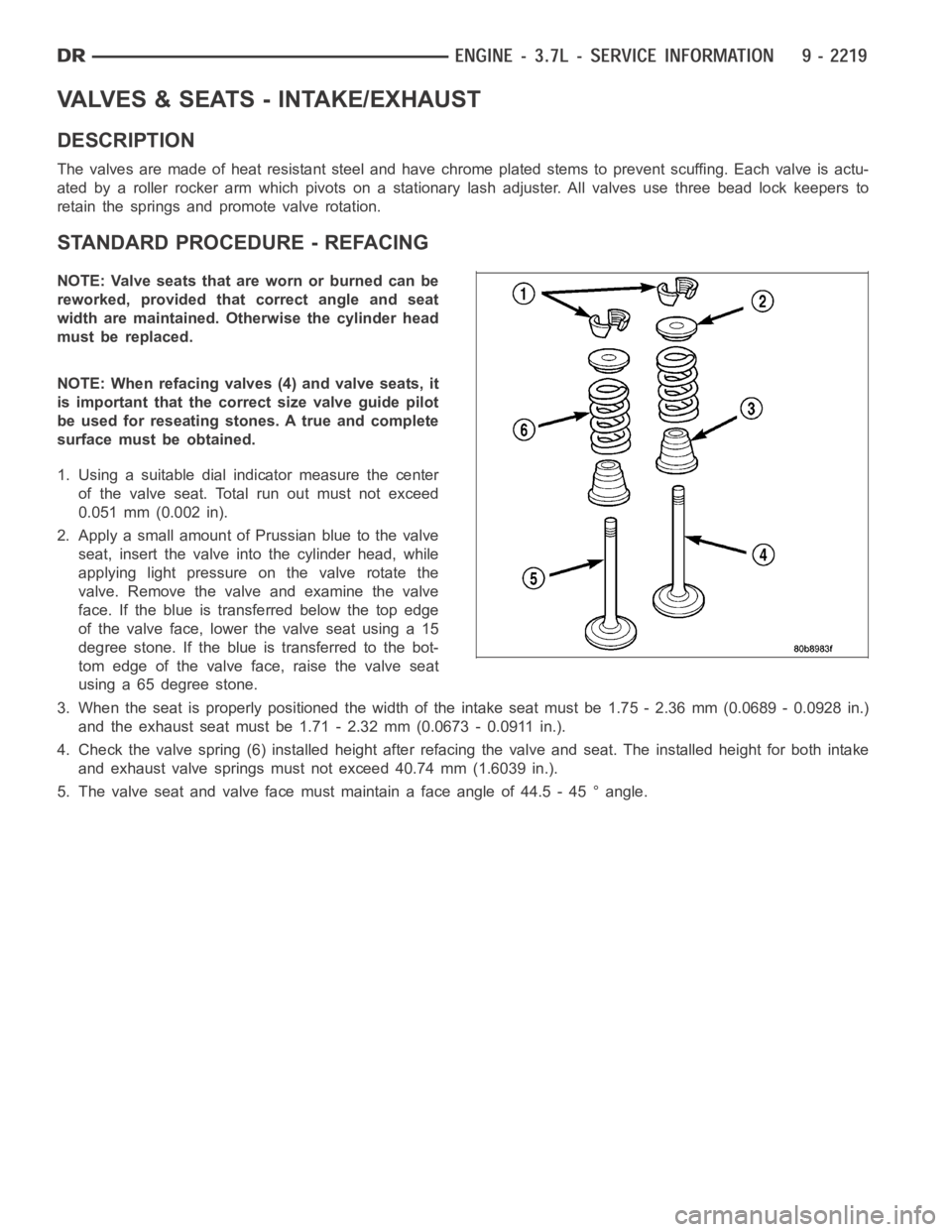
The valves are made of heat resistant steel and have chrome plated stems to prevent scuffing. Each valve is actu-
ated by a roller rocker arm which pivots on a stationary lash adjuster. All valves use three bead lock keepers to
retain the springs and promote valve rotation.
STANDARD PROCEDURE - REFACING
NOTE: Valve seats that are worn or burned can be
reworked, provided that correct angle and seat
width are maintained. Otherwise the cylinder head
must be replaced.
NOTE: When refacing valves (4) and valve seats, it
is important that the correct size valve guide pilot
be used for reseating stones. A true and complete
surface must be obtained.
1. Using a suitable dial indicator measure the center
of the valve seat. Total run out must not exceed
0.051 mm (0.002 in).
2. Apply a small amount of Prussian blue to the valve
seat, insert the valve into the cylinder head, while
applying light pressure on the valve rotate the
valve. Remove the valve and examine the valve
face. If the blue is transferred below the top edge
of the valve face, lower the valve seat using a 15
degree stone. If the blue is transferred to the bot-
tom edge of the valve face, raise the valve seat
using a 65 degree stone.
3. When the seat is properly positioned the width of the intake seat must be 1.75 - 2.36 mm (0.0689 - 0.0928 in.)
and the exhaust seat must be 1.71 - 2.32 mm (0.0673 - 0.0911 in.).
4. Check the valve spring (6) installed height after refacing the valve andseat. The installed height for both intake
and exhaust valve springs must not exceed 40.74 mm (1.6039 in.).
5. The valve seat and valve face must maintain a face angle of 44.5 - 45 ° angle.
Page 1569 of 5267
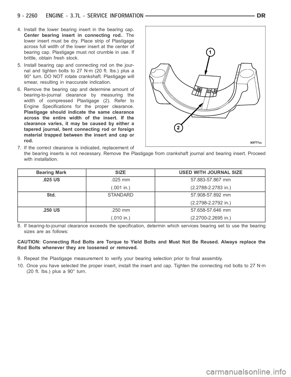
4. Install the lower bearing insert in the bearing cap.
Center bearing insert in connecting rod..The
lower insert must be dry. Place strip of Plastigage
across full width of the lower insert at the center of
bearing cap. Plastigage must not crumble in use. If
brittle, obtain fresh stock.
5. Install bearing cap and connecting rod on the jour-
nal and tighten bolts to 27 Nꞏm (20 ft. lbs.) plus a
90° turn. DO NOT rotate crankshaft. Plastigage will
smear, resulting in inaccurate indication.
6. Remove the bearing cap and determine amount of
bearing-to-journal clearance by measuring the
width of compressed Plastigage (2). Refer to
Engine Specifications for the proper clearance.
Plastigage should indicate the same clearance
across the entire width of the insert. If the
clearancevaries,itmaybecausedbyeithera
tapered journal, bent connecting rod or foreign
material trapped between the insert and cap or
rod.
7. If the correct clearance is indicated, replacement of
the bearing inserts is not necessary. Remove the Plastigage from crankshaft journal and bearing insert. Proceed
with installation.
Bearing Mark SIZE USED WITH JOURNAL SIZE
.025 US.025 mm 57.883-57.867 mm
(.001 in.) (2.2788-2.2783 in.)
Std.STANDARD 57.908-57.892 mm
(2.2798-2.2792 in.)
.250 US.250 mm 57.658-57.646 mm
(.010 in.) (2.2700-2.2695 in.)
8. If bearing-to-journal clearance exceeds the specification, determinwhich services bearing set to use the bearing
sizes are as follows:
CAUTION: Connecting Rod Bolts are Torque to Yield Bolts and Must Not Be Reused. Always replace the
Rod Bolts whenever they are loosened or removed.
9. Repeat the Plastigage measurement to verify your bearing selection prior to final assembly.
10. Once you have selected the proper insert, install the insert and cap. Tighten the connecting rod bolts to 27 Nꞏm
(20 ft. lbs.) plus a 90° turn.
Page 1580 of 5267
MOUNT-FRONT
REMOVAL
2WD
1. Disconnect the negative cable from the battery.
CAUTION: Remove the viscous fan before raising engine. Failure to do so maycause damage to the fan
blade, fan clutch and fan shroud.
2. Remove the viscous fan (Refer to 7 - COOLING/ENGINE/FAN DRIVE VISCOUS CLUTCH - REMOVAL).
3. Raise the vehicle.
4. Remove the engine oil filter.
5. Remove the oil drain trough.
6. Support the engine with a suitable jack and a block of wood across the fullwidth of the engine oil pan.
7. Support the front axle with a suitable jack.
8. Remove the (4) bolts that attach the engine mounts to the front axle.
9. Remove the (3) bolts that attach the front axle to the left engine bracket.
10. Lower the front axle.
11. Remove the through bolts
12. Raise the engine far enough to be able to remove the left and right enginemounts.
13. Remove the (8) mount to engine attaching bolts
14. Remove the engine mounts.
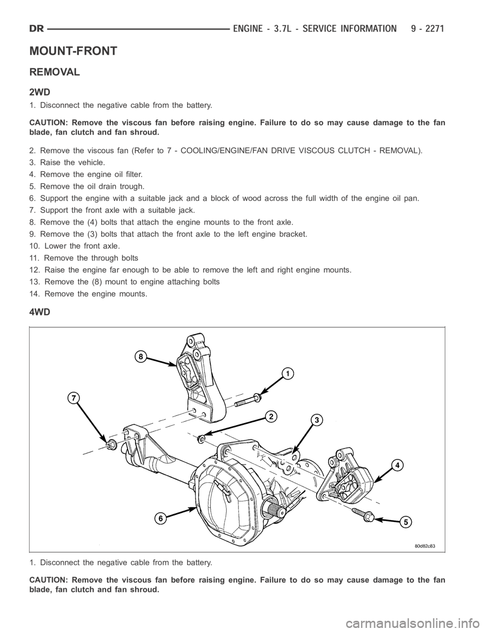
4WD
1. Disconnect the negative cable from the battery.
CAUTION: Remove the viscous fan before raising engine. Failure to do so maycause damage to the fan
blade, fan clutch and fan shroud.
Page 1581 of 5267
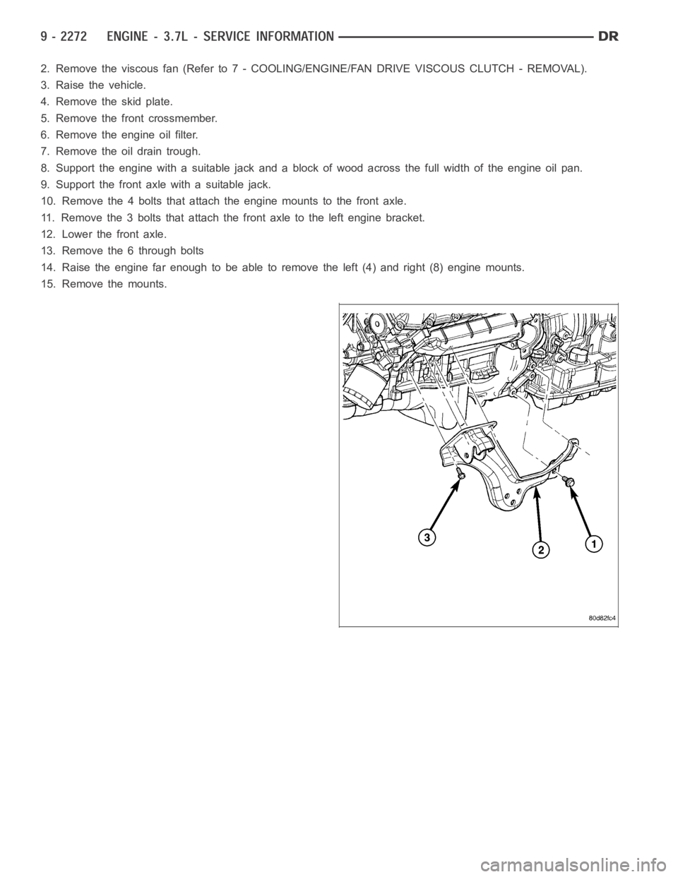
2. Remove the viscous fan (Refer to 7 - COOLING/ENGINE/FAN DRIVE VISCOUS CLUTCH - REMOVAL).
3. Raise the vehicle.
4. Removetheskidplate.
5. Remove the front crossmember.
6. Remove the engine oil filter.
7. Remove the oil drain trough.
8. Support the engine with a suitable jack and a block of wood across the fullwidth of the engine oil pan.
9. Support the front axle with a suitable jack.
10. Remove the 4 bolts that attach the engine mounts to the front axle.
11. Remove the 3 bolts that attach the front axle to the left engine bracket.
12. Lower the front axle.
13. Remove the 6 through bolts
14. Raise the engine far enough to be able to remove the left (4) and right (8)engine mounts.
15. Remove the mounts.
Page 1629 of 5267
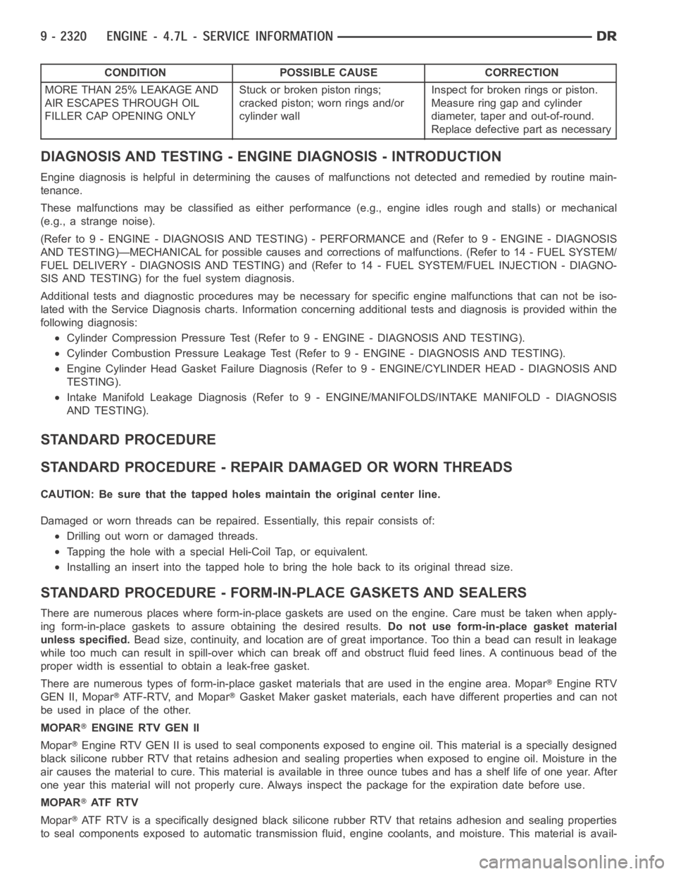
CONDITION POSSIBLE CAUSE CORRECTION
MORE THAN 25% LEAKAGE AND
AIR ESCAPES THROUGH OIL
FILLER CAP OPENING ONLYStuckorbrokenpistonrings;
cracked piston; worn rings and/or
cylinder wallInspect for broken rings or piston.
Measure ring gap and cylinder
diameter, taper and out-of-round.
Replace defective part as necessary
DIAGNOSIS AND TESTING - ENGINE DIAGNOSIS - INTRODUCTION
Engine diagnosis is helpful in determining the causes of malfunctions notdetected and remedied by routine main-
tenance.
These malfunctions may be classified as either performance (e.g., engineidles rough and stalls) or mechanical
(e.g., a strange noise).
(Refer to 9 - ENGINE - DIAGNOSIS AND TESTING) - PERFORMANCE and (Refer to 9 - ENGINE - DIAGNOSIS
AND TESTING)—MECHANICAL for possible causes and corrections of malfunctions. (Refer to 14 - FUEL SYSTEM/
FUEL DELIVERY - DIAGNOSIS AND TESTING) and (Refer to 14 - FUEL SYSTEM/FUEL INJECTION - DIAGNO-
SIS AND TESTING) for the fuel system diagnosis.
Additional tests and diagnostic procedures may be necessary for specificengine malfunctions that can not be iso-
lated with the Service Diagnosis charts. Information concerning additional tests and diagnosis is provided within the
following diagnosis:
Cylinder Compression Pressure Test (Refer to 9 - ENGINE - DIAGNOSIS AND TESTING).
Cylinder Combustion Pressure LeakageTest (Refer to 9 - ENGINE - DIAGNOSISAND TESTING).
Engine Cylinder Head Gasket Failure Diagnosis (Refer to 9 - ENGINE/CYLINDER HEAD - DIAGNOSIS AND
TESTING).
Intake Manifold Leakage Diagnosis (Refer to 9 - ENGINE/MANIFOLDS/INTAKEMANIFOLD - DIAGNOSIS
AND TESTING).
STANDARD PROCEDURE
STANDARD PROCEDURE - REPAIR DAMAGED OR WORN THREADS
CAUTION: Be sure that the tapped holes maintain the original center line.
Damaged or worn threads can be repaired. Essentially, this repair consistsof:
Drilling out worn or damaged threads.
Tapping the hole with a special Heli-Coil Tap, or equivalent.
Installing an insert into the tapped hole to bring the hole back to its original thread size.
STANDARD PROCEDURE - FORM-IN-PLACE GASKETS AND SEALERS
There are numerous places where form-in-place gaskets are used on the engine. Care must be taken when apply-
ing form-in-place gaskets to assure obtaining the desired results.Do not use form-in-place gasket material
unless specified.Bead size, continuity, and location are of great importance. Too thin a bead can result in leakage
while too much can result in spill-overwhich can break off and obstruct fluid feed lines. A continuous bead of the
proper width is essential to obtain a leak-free gasket.
There are numerous types of form-in-place gasket materials that are used in the engine area. Mopar
Engine RTV
GEN II, Mopar
ATF-RTV, and MoparGasket Maker gasket materials, each have different properties and can not
be used in place of the other.
MOPAR
ENGINE RTV GEN II
Mopar
Engine RTV GEN II is used to seal components exposed to engine oil. This material is a specially designed
black silicone rubber RTV that retains adhesion and sealing properties when exposed to engine oil. Moisture in the
air causes the material to cure. This material is available in three ounce tubes and has a shelf life of one year. After
one year this material will not properly cure. Always inspect the package for the expiration date before use.
MOPAR
AT F R T V
Mopar
ATF RTV is a specifically designed black silicone rubber RTV that retains adhesion and sealing properties
to seal components exposed to automatic transmission fluid, engine coolants, and moisture. This material is avail-
Page 1641 of 5267
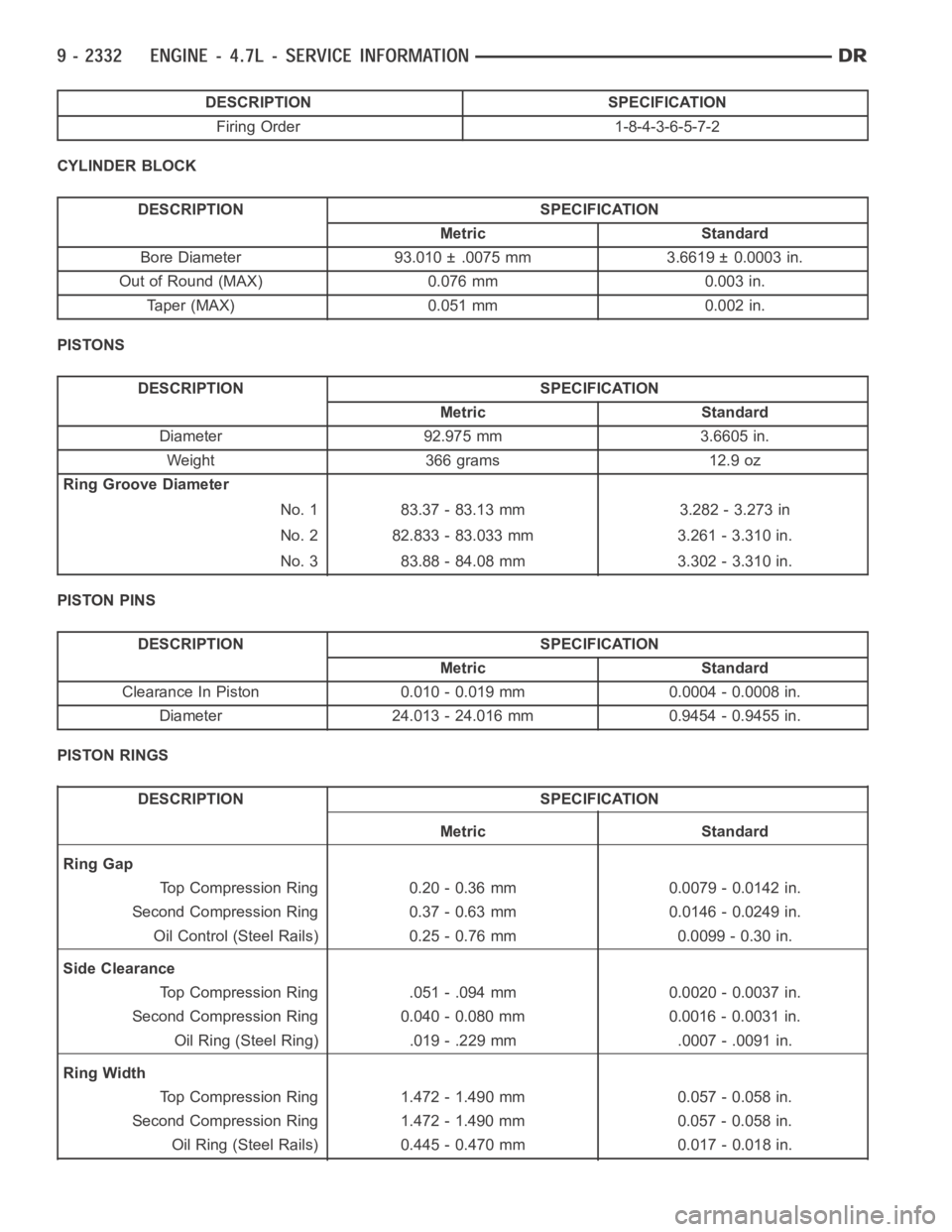
DESCRIPTION SPECIFICATION
Firing Order 1-8-4-3-6-5-7-2
CYLINDER BLOCK
DESCRIPTION SPECIFICATION
Metric Standard
Bore Diameter 93.010 ± .0075 mm 3.6619 ± 0.0003 in.
Out of Round (MAX) 0.076 mm 0.003 in.
Taper (MAX) 0.051 mm 0.002 in.
PISTONS
DESCRIPTION SPECIFICATION
Metric Standard
Diameter 92.975 mm 3.6605 in.
Weight 366 grams 12.9 oz
Ring Groove Diameter
No. 1 83.37 - 83.13 mm 3.282 - 3.273 in
No. 2 82.833 - 83.033 mm 3.261 - 3.310 in.
No. 3 83.88 - 84.08 mm 3.302 - 3.310 in.
PISTON PINS
DESCRIPTION SPECIFICATION
Metric Standard
Clearance In Piston 0.010 - 0.019 mm 0.0004 - 0.0008 in.
Diameter 24.013 - 24.016 mm 0.9454 - 0.9455 in.
PISTON RINGS
DESCRIPTION SPECIFICATION
Metric Standard
Ring Gap
Top Compression Ring 0.20 - 0.36 mm 0.0079 - 0.0142 in.
Second Compression Ring 0.37 - 0.63 mm 0.0146 - 0.0249 in.
Oil Control (Steel Rails) 0.25 - 0.76 mm 0.0099 - 0.30 in.
Side Clearance
Top Compression Ring .051 - .094 mm 0.0020 - 0.0037 in.
Second Compression Ring 0.040 - 0.080 mm 0.0016 - 0.0031 in.
Oil Ring (Steel Ring) .019 - .229 mm .0007 - .0091 in.
Ring Width
Top Compression Ring 1.472 - 1.490 mm 0.057 - 0.058 in.
Second Compression Ring 1.472 - 1.490 mm 0.057 - 0.058 in.
Oil Ring (Steel Rails) 0.445 - 0.470 mm 0.017 - 0.018 in.
Page 1691 of 5267
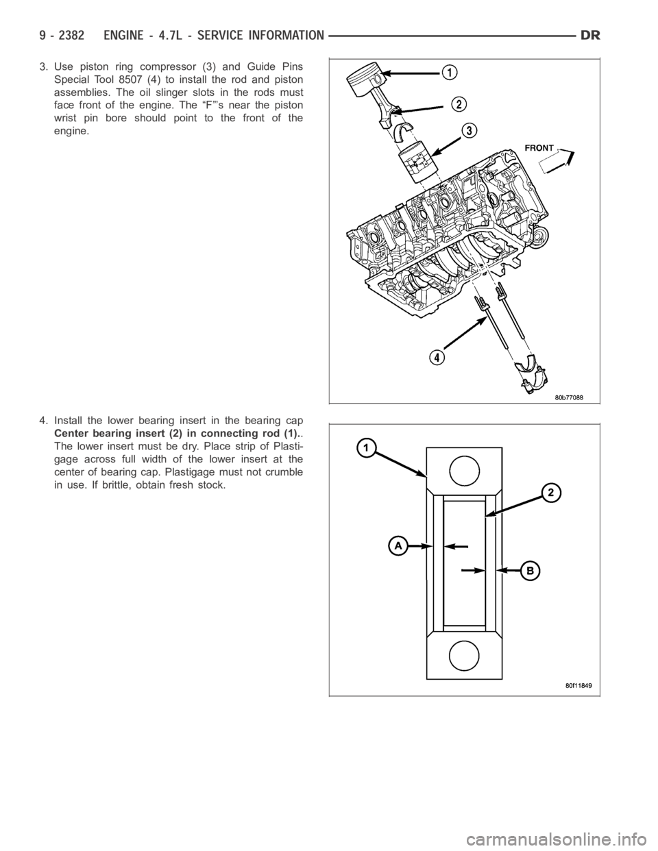
3. Use piston ring compressor (3) and Guide Pins
Special Tool 8507 (4) to install the rod and piston
assemblies. The oil slinger slots in the rods must
face front of the engine. The “F”’s near the piston
wrist pin bore should point to the front of the
engine.
4. Install the lower bearing insert in the bearing cap
Center bearing insert (2) in connecting rod (1)..
The lower insert must be dry. Place strip of Plasti-
gage across full width of the lower insert at the
center of bearing cap. Plastigage must not crumble
in use. If brittle, obtain fresh stock.