2006 DODGE RAM SRT-10 width
[x] Cancel search: widthPage 2294 of 5267
Battery voltage (12 volts +) is supplied to the injectors through the ASD relay. The ASD relay will shut-down the 12
volt power source to the fuel injectors if the PCM senses the ignition is on,but the engine is not running. This
occurs after the engine has not been running for approximately 1.8 seconds.
The PCM determines injector on-time (pulse width) based on various inputs.
REMOVAL
3.7/4.7/ 5.7L
1. Remove fuel rail. (Refer to 14 - FUEL SYSTEM/
FUEL DELIVERY/FUEL RAIL - REMOVAL)
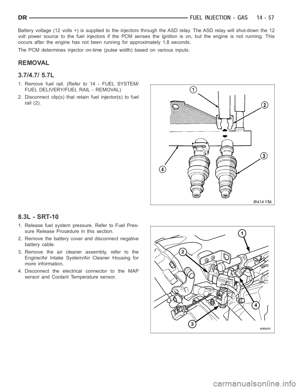
2. Disconnect clip(s) that retain fuel injector(s) to fuel
rail (2).
8.3L - SRT-10
1. Release fuel system pressure. Refer to Fuel Pres-
sure Release Procedure in this section.
2. Remove the battery cover and disconnect negative
battery cable.
3. Remove the air cleaner assembly, refer to the
Engine/Air Intake System/Air Cleaner Housing for
more information.
4. Disconnect the electrical connector to the MAP
sensor and Coolant Temperature sensor.
Page 2307 of 5267
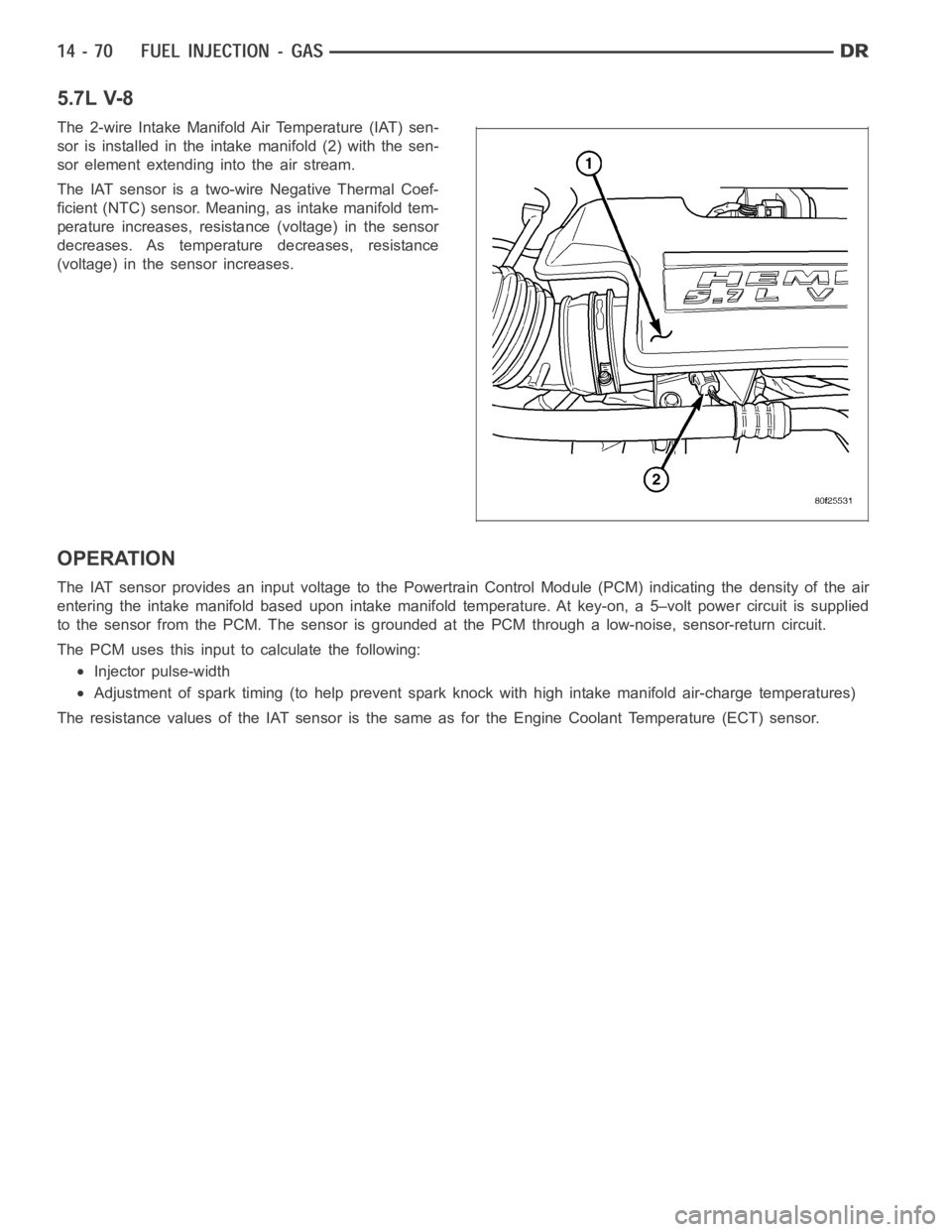
5.7L V-8
The 2-wire Intake Manifold Air Temperature (IAT) sen-
sor is installed in the intake manifold (2) with the sen-
sor element extending into the air stream.
The IAT sensor is a two-wire Negative Thermal Coef-
ficient (NTC) sensor. Meaning, as intake manifold tem-
perature increases, resistance (voltage) in the sensor
decreases. As temperature decreases, resistance
(voltage) in the sensor increases.
OPERATION
The IAT sensor provides an input voltage to the Powertrain Control Module (PCM) indicating the density of the air
entering the intake manifold based upon intake manifold temperature. At key-on, a 5–volt power circuit is supplied
to the sensor from the PCM. The sensor is grounded at the PCM through a low-noise, sensor-return circuit.
The PCM uses this input to calculate the following:
Injector pulse-width
Adjustment of spark timing (to help prevent spark knock with high intake manifold air-charge temperatures)
The resistance values of the IAT sensor is the same as for the Engine CoolantTemperature (ECT) sensor.
Page 2314 of 5267

5.7L V-8
The Manifold Absolute Pressure (MAP) sensor is
mounted to the front of the intake manifold air plenum
box.
8.3L - SRT-10
The MAP sensor (2) mounts to the drivers side intake
manifold plenum.
OPERATION
The MAP sensor is used as an input to the Powertrain Control Module (PCM). Itcontains a silicon based sensing
unit to provide data on the manifold vacuum that draws the air/fuel mixtureinto the combustion chamber. The PCM
requires this information to determine injector pulse width and spark advance. When manifold absolute pressure
(MAP) equals Barometric pressure, the pulse width will be at maximum.
A 5 volt reference is supplied from the PCM and returns a voltage signal to the PCM that reflects manifold pressure.
The zero pressure reading is 0.5V and full scale is 4.5V. For a pressure swing of 0–15 psi, the voltage changes
4.0V. To operate the sensor, it is supplied a regulated 4.8 to 5.1 volts. Ground is provided through the low-noise,
sensor return circuit at the PCM.
The MAP sensor input is the number one contributor to fuel injector pulse width. The most important function of the
MAP sensor is to determine barometric pressure. The PCM needs to know if thevehicle is at sea level or at a
Page 2315 of 5267
higher altitude, because the air density changes with altitude. It will also help to correct for varying barometric pres-
sure. Barometric pressure and altitude have a direct inverse correlation; as altitude goes up, barometric goes down.
At key-on, the PCM powers up and looks at MAP voltage, and based upon the voltage it sees, it knows the current
barometric pressure (relative to altitude). Once the engine starts, the PCM looks at the voltage again, continuously
every 12 milliseconds, and compares the current voltage to what it was at key-on. The difference between current
voltage and what it was at key-on, is manifold vacuum.
During key-on (engine not running) the sensor reads (updates) barometricpressure. A normal range can be
obtained by monitoring a known good sensor.
As the altitude increases, the air becomes thinner (less oxygen). If a vehicleisstartedanddriventoaverydifferent
altitude than where it was at key-on, the barometric pressure needs to be updated. Any time the PCM sees Wide
Open Throttle (WOT), based upon Throttle Position Sensor (TPS) angle and RPM, it will update barometric pressure
in the MAP memory cell. With periodic updates, the PCM can make its calculations more effectively.
The PCM uses the MAP sensor input to aid in calculating the following:
Manifold pressure
Barometric pressure
Engine load
Injector pulse-width
Spark-advance programs
Shift-point strategies (certain automatic transmissions only)
Idle speed
Decel fuel shutoff
The MAP sensor signal is provided from asingle piezoresistive element located in the center of a diaphragm. The
element and diaphragm are both made ofsilicone. As manifold pressure changes, the diaphragm moves causing
the element to deflect, which stresses the silicone. When silicone is exposed to stress, its resistance changes. As
manifold vacuum increases, the MAP sensor input voltage decreases proportionally. The sensor also contains elec-
tronics that condition the signal and provide temperature compensation.
The PCM recognizes a decrease in manifold pressure by monitoring a decrease in voltage from the reading stored
in the barometric pressure memory cell. The MAP sensor is a linear sensor; meaning as pressure changes, voltage
changes proportionately. The range of voltage output from the sensor is usually between 4.6 volts at sea level to as
low as 0.3 volts at 26 in. of Hg. Barometric pressure is the pressure exertedby the atmosphere upon an object. At
sea level on a standard day, no storm, barometric pressure is approximately 29.92 in Hg. For every 100 feet of
altitude, barometric pressure drops 0.10 in. Hg. If a storm goes through, it can change barometric pressure from
what should be present for that altitude. You should know what the average pressure and corresponding barometric
pressure is for your area.
Page 2336 of 5267
OPERATION
The 5.7L V-8 engine does not use a separate Throttle Position Sensor (TPS) on the throttle body.
The 3-wire TPS provides the Powertrain Control Module (PCM) with an input signal (voltage) that represents the
throttle blade position of the throttle body. The sensor is connected to the throttle blade shaft. As the position of the
throttle blade changes, the output voltage of the TPS changes.
The PCM supplies approximately 5 volts to the TPS. The TPS output voltage (input signal to the PCM) represents
the throttle blade position. The PCM receives an input signal voltage fromthe TPS. This will vary in an approximate
range of from .26 volts at minimum throttle opening (idle), to 4.49 volts atwide open throttle. Along with inputs from
other sensors, the PCM uses the TPS input to determine current engine operating conditions. In response to engine
operating conditions, the PCM will adjust fuel injector pulse width and ignition timing.
The PCM needs to identify the actions and position of the throttle blade at all times. This information is needed to
assist in performing the following calculations:
Ignition timing advance
Fuel injection pulse-width
Idle (learned value or minimum TPS)
Off-idle (0.06 volt)
Wide Open Throttle (WOT) open loop (2.608 volts above learned idle voltage)
Deceleration fuel lean out
Fuel cutoff during cranking at WOT (2.608 volts above learned idle voltage)
A/C WOT cutoff (certain automatic transmissions only)
REMOVAL
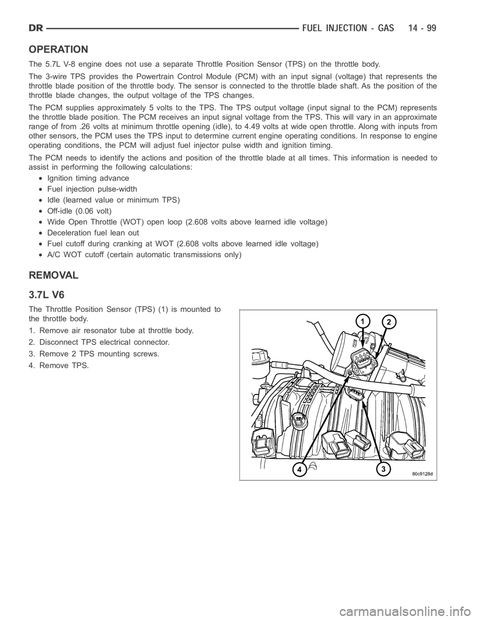
3.7L V6
The Throttle Position Sensor (TPS) (1) is mounted to
the throttle body.
1. Remove air resonator tube at throttle body.
2. Disconnect TPS electrical connector.
3. Remove 2 TPS mounting screws.
4. Remove TPS.
Page 3058 of 5267
SOLENOID
DESCRIPTION
The typical electrical solenoid used in automotive applications is a linear actuator. It is a device that produces
motion in a straight line. This straight line motion can be either forward or backward in direction, and short or long
distance.
A solenoid is an electromechanical device that uses a magnetic force to perform work. It consists of a coil of wire,
wrapped around a magnetic core made from steel or iron, and a spring loaded,movable plunger, which performs
the work, or straight line motion.
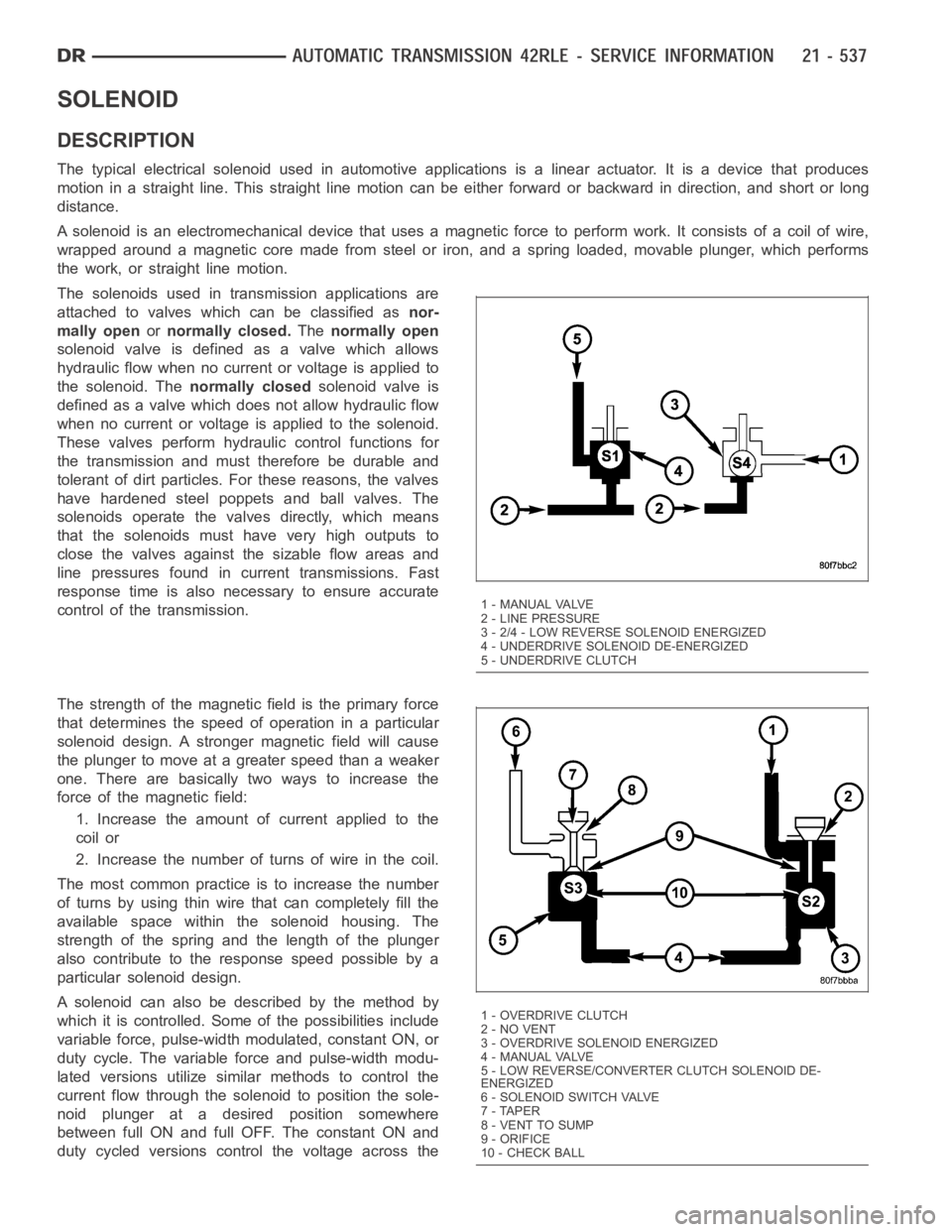
The solenoids used in transmission applications are
attached to valves which can be classified asnor-
mally openornormally closed.Thenormally open
solenoid valve is defined as a valve which allows
hydraulic flow when no current or voltage is applied to
the solenoid. Thenormally closedsolenoid valve is
defined as a valve which does not allow hydraulic flow
when no current or voltage is applied to the solenoid.
These valves perform hydraulic control functions for
the transmission and must therefore be durable and
tolerant of dirt particles. For these reasons, the valves
have hardened steel poppets and ball valves. The
solenoids operate the valves directly, which means
that the solenoids must have very high outputs to
close the valves against the sizable flow areas and
line pressures found in current transmissions. Fast
response time is also necessary to ensure accurate
control of the transmission.
The strength of the magnetic field is the primary force
that determines the speed of operation in a particular
solenoid design. A stronger magnetic field will cause
the plunger to move at a greater speed than a weaker
one. There are basically two ways to increase the
force of the magnetic field:
1. Increase the amount of current applied to the
coil or
2. Increase the number of turns of wire in the coil.
The most common practice is to increase the number
of turns by using thin wire that can completely fill the
available space within the solenoid housing. The
strength of the spring and the length of the plunger
also contribute to the response speed possible by a
particular solenoid design.
A solenoid can also be described by the method by
which it is controlled. Some of the possibilities include
variable force, pulse-width modulated, constant ON, or
duty cycle. The variable force and pulse-width modu-
lated versions utilize similar methods to control the
current flow through the solenoid to position the sole-
noid plunger at a desired position somewhere
between full ON and full OFF. The constant ON and
duty cycled versions control the voltage across the
1 - MANUAL VALVE
2 - LINE PRESSURE
3 - 2/4 - LOW REVERSE SOLENOID ENERGIZED
4 - UNDERDRIVE SOLENOID DE-ENERGIZED
5 - UNDERDRIVE CLUTCH
1-OVERDRIVECLUTCH
2 - NO VENT
3 - OVERDRIVE SOLENOID ENERGIZED
4 - MANUAL VALVE
5 - LOW REVERSE/CONVERTER CLUTCH SOLENOID DE-
ENERGIZED
6-SOLENOIDSWITCHVALVE
7 - TAPER
8 - VENT TO SUMP
9 - ORIFICE
10 - CHECK BALL
Page 4114 of 5267
OIL PUMP AND REAR CASE
CAUTION: Do not remove the bolts holding the oil
pump cover to the rear case half. The oil pump
cover is aligned to the rear output shaft inner
bearing race and will become mis-aligned if the
bolts are loosened. If the transfer case failure has
generated any debris which may have become
trapped in the oil pump. the rear case and oil
pump assembly MUST be replaced.
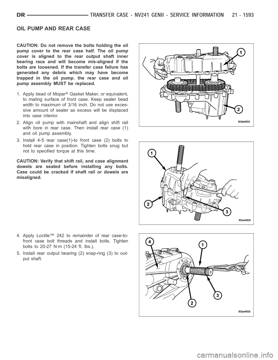
1. Apply bead of Mopar
Gasket Maker, or equivalent,
to mating surface of front case. Keep sealer bead
width to maximum of 3/16 inch. Do not use exces-
sive amount of sealer as excess will be displaced
into case interior.
2. Align oil pump with mainshaft and align shift rail
with bore in rear case. Then install rear case (1)
and oil pump assembly.
3. Install 4-5 rear case(1)-to front case (2) bolts to
hold rear case in position. Tighten bolts snug but
not to specified torque at this time.
CAUTION: Verify that shift rail, and case alignment
dowels are seated before installing any bolts.
Case could be cracked if shaft rail or dowels are
misaligned.
4. Apply Loctite™ 242 to remainder of rear case-to-
front case bolt threads and install bolts. Tighten
bolts to 20-27 Nꞏm (15-24 ft. lbs.),
5. Install rear output bearing (2) snap-ring (3) to out-
put shaft.
Page 4115 of 5267
SEAL BOOT
1. Install the front output shaft seal slinger with Oil Slinger Installer 8840. Install the slinger onto the shaft until the
tool contacts the rear of the output shaft.
2. Install a new seal boot clamp onto the seal boot.
3. Install the seal boot and clamp onto the slinger hub and tighten the clampwith Crimp Tool C-4975-A.
REAR EXTENSION
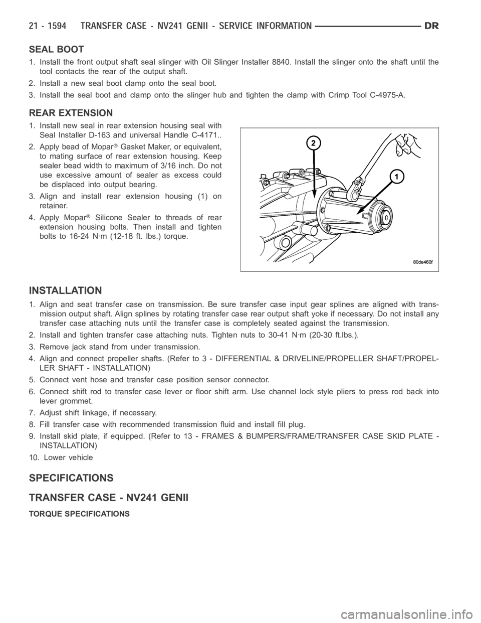
1. Install new seal in rear extension housing seal with
Seal Installer D-163 and universal Handle C-4171..
2. Apply bead of Mopar
Gasket Maker, or equivalent,
to mating surface of rear extension housing. Keep
sealer bead width to maximum of 3/16 inch. Do not
use excessive amount of sealer as excess could
be displaced into output bearing.
3. Align and install rear extension housing (1) on
retainer.
4. Apply Mopar
Silicone Sealer to threads of rear
extension housing bolts. Then install and tighten
bolts to 16-24 Nꞏm (12-18 ft. lbs.) torque.
INSTALLATION
1. Align and seat transfer case on transmission. Be sure transfer case input gear splines are aligned with trans-
mission output shaft. Align splines by rotating transfer case rear outputshaft yoke if necessary. Do not install any
transfer case attaching nuts until the transfer case is completely seatedagainst the transmission.
2. Install and tighten transfer case attaching nuts. Tighten nuts to 30-41Nꞏm (20-30 ft.lbs.).
3. Remove jack stand from under transmission.
4. Align and connect propeller shafts. (Refer to 3 - DIFFERENTIAL & DRIVELINE/PROPELLER SHAFT/PROPEL-
LER SHAFT - INSTALLATION)
5. Connect vent hose and transfer case position sensor connector.
6. Connect shift rod to transfer case lever or floor shift arm. Use channel lock style pliers to press rod back into
lever grommet.
7. Adjust shift linkage, if necessary.
8. Fill transfer case with recommended transmission fluid and install fillplug.
9. Install skid plate, if equipped. (Refer to 13 - FRAMES & BUMPERS/FRAME/TRANSFER CASE SKID PLATE -
INSTALLATION)
10. Lower vehicle
SPECIFICATIONS
TRANSFER CASE - NV241 GENII
TORQUE SPECIFICATIONS