2006 DODGE RAM SRT-10 width
[x] Cancel search: widthPage 1103 of 5267
When Monitored:
With battery voltage greater than 10.4 volts, the auto shutdown relay energized, injector pulse width less than
10ms, and engine speed less than 3000 rpm.
Set Condition:
This trouble code takes .64 to 10.0 seconds to set when no inductive kick is sensed .18ms after injector turn
off, and with no other injectors on.
Possible Causes
(K342) ASD RELAY OUTPUT CIRCUIT
(K38) INJECTOR CONTROL NO.5 CIRCUIT OPEN
(K38) INJECTOR CONTROL NO.5 CIRCUIT SHORTED TO GROUND
FUEL INJECTOR
PCM
Always perform the Pre-Diagnostic Troubleshooting procedure before proceeding. (Refer to 9 - ENGINE -
DIAGNOSIS AND TESTING).
Diagnostic Test
1.ACTIVE DTC
Ignition on, engine not running.
With a scan tool, read DTCs.
Is the DTC active at this time?
Ye s>>
Go To 2
No>>
Refer to the INTERMITTENT CONDITION Diagnostic Procedure.
Perform the POWERTRAIN VERIFICATION TEST. (Refer to 9 - ENGINE - STANDARD PROCEDURE)
2.(K342) ASD RELAY OUTPUT CIRCUIT
Turn the ignition off.
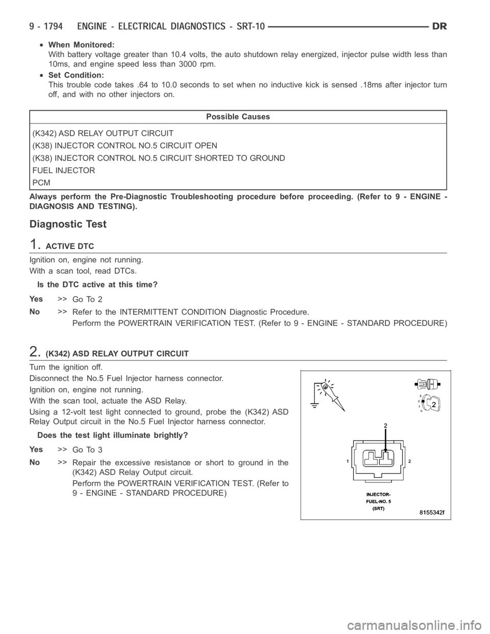
Disconnect the No.5 Fuel Injector harness connector.
Ignition on, engine not running.
With the scan tool, actuate the ASD Relay.
Using a 12-volt test light connected to ground, probe the (K342) ASD
Relay Output circuit in the No.5 Fuel Injector harness connector.
Does the test light illuminate brightly?
Ye s>>
Go To 3
No>>
Repair the excessive resistanceorshorttogroundinthe
(K342) ASD Relay Output circuit.
Perform the POWERTRAIN VERIFICATION TEST. (Refer to
9 - ENGINE - STANDARD PROCEDURE)
Page 1107 of 5267
When Monitored:
With battery voltage greater than 10.4 volts, the auto shutdown relay energized, injector pulse width less than
10ms, and engine speed less than 3000 rpm.
Set Condition:
This trouble code takes .64 to 10.0 seconds to set when no inductive kick is sensed .18ms after injector turn
off, and with no other injectors on.
Possible Causes
(K342) ASD RELAY OUTPUT CIRCUIT
(K58) INJECTOR CONTROL NO.6 CIRCUIT OPEN
(K58) INJECTOR CONTROL NO.6 CIRCUIT SHORTED TO GROUND
FUEL INJECTOR
PCM
Always perform the Pre-Diagnostic Troubleshooting procedure before proceeding. (Refer to 9 - ENGINE -
DIAGNOSIS AND TESTING).
Diagnostic Test
1.ACTIVE DTC
Ignition on, engine not running.
With a scan tool, read DTCs.
Is the DTC active at this time?
Ye s>>
Go To 2
No>>
Refer to the INTERMITTENT CONDITION Diagnostic Procedure.
Perform the POWERTRAIN VERIFICATION TEST. (Refer to 9 - ENGINE - STANDARD PROCEDURE)
2.(K342) ASD RELAY OUTPUT CIRCUIT
Turn the ignition off.
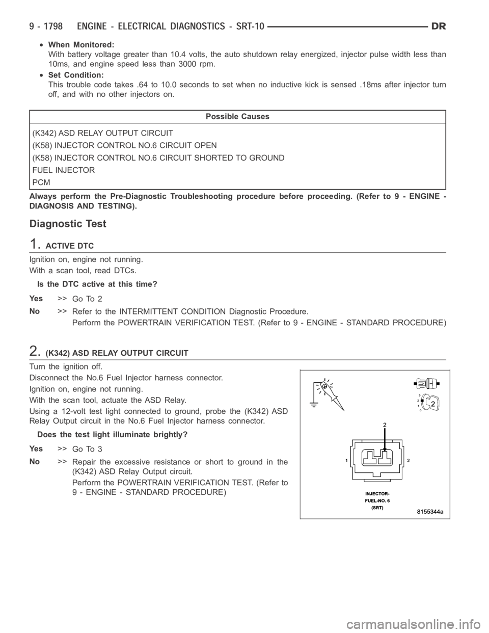
Disconnect the No.6 Fuel Injector harness connector.
Ignition on, engine not running.
With the scan tool, actuate the ASD Relay.
Using a 12-volt test light connected to ground, probe the (K342) ASD
Relay Output circuit in the No.6 Fuel Injector harness connector.
Does the test light illuminate brightly?
Ye s>>
Go To 3
No>>
Repair the excessive resistanceorshorttogroundinthe
(K342) ASD Relay Output circuit.
Perform the POWERTRAIN VERIFICATION TEST. (Refer to
9 - ENGINE - STANDARD PROCEDURE)
Page 1111 of 5267
When Monitored:
With battery voltage greater than 10.4 volts, the auto shutdown relay energized, injector pulse width less than
10ms, and engine speed less than 3000 rpm.
Set Condition:
This trouble code takes .64 to 10.0 seconds to set when no inductive kick is sensed .18ms after injector turn
off, and with no other injectors on.
Possible Causes
(K342) ASD RELAY OUTPUT CIRCUIT
(K26) INJECTOR CONTROL NO.7 CIRCUIT OPEN
(K26) INJECTOR CONTROL NO.7 CIRCUIT SHORTED TO GROUND
FUEL INJECTOR
PCM
Always perform the Pre-Diagnostic Troubleshooting procedure before proceeding. (Refer to 9 - ENGINE -
DIAGNOSIS AND TESTING).
Diagnostic Test
1.ACTIVE DTC
Ignition on, engine not running.
With a scan tool, read DTCs.
Is the DTC active at this time?
Ye s>>
Go To 2
No>>
Refer to the INTERMITTENT CONDITION Diagnostic Procedure.
Perform the POWERTRAIN VERIFICATION TEST. (Refer to 9 - ENGINE - STANDARD PROCEDURE)
2.(K342) ASD RELAY OUTPUT CIRCUIT
Turn the ignition off.
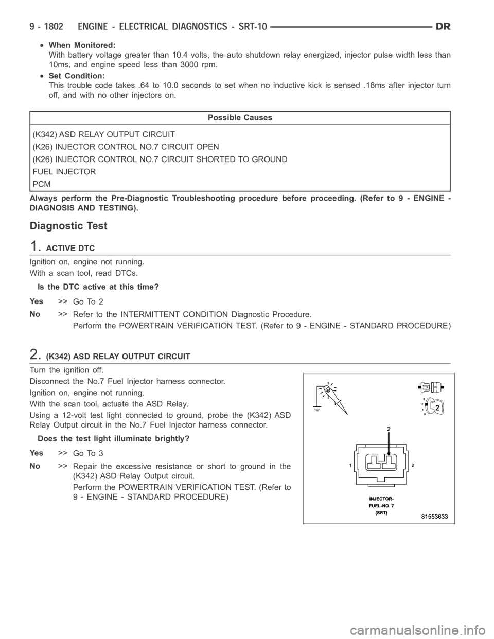
Disconnect the No.7 Fuel Injector harness connector.
Ignition on, engine not running.
With the scan tool, actuate the ASD Relay.
Using a 12-volt test light connected to ground, probe the (K342) ASD
Relay Output circuit in the No.7 Fuel Injector harness connector.
Does the test light illuminate brightly?
Ye s>>
Go To 3
No>>
Repair the excessive resistanceorshorttogroundinthe
(K342) ASD Relay Output circuit.
Perform the POWERTRAIN VERIFICATION TEST. (Refer to
9 - ENGINE - STANDARD PROCEDURE)
Page 1115 of 5267
When Monitored:
With battery voltage greater than 10.4 volts, the auto shutdown relay energized, injector pulse width less than
10ms, and engine speed less than 3000 rpm.
Set Condition:
This trouble code takes .64 to 10.0 seconds to set when no inductive kick is sensed .18ms after injector turn
off, and with no other injectors on.
Possible Causes
(K342) ASD RELAY OUTPUT CIRCUIT
(K28) INJECTOR CONTROL NO.8 CIRCUIT OPEN
(K28) INJECTOR CONTROL NO.8 CIRCUIT SHORTED TO GROUND
FUEL INJECTOR
PCM
Always perform the Pre-Diagnostic Troubleshooting procedure before proceeding. (Refer to 9 - ENGINE -
DIAGNOSIS AND TESTING).
Diagnostic Test
1.ACTIVE DTC
Ignition on, engine not running.
With a scan tool, read DTC.
Is the DTC active at this time?
Ye s>>
Go To 2
No>>
Refer to the INTERMITTENT CONDITION Diagnostic Procedure.
Perform the POWERTRAIN VERIFICATION TEST. (Refer to 9 - ENGINE - STANDARD PROCEDURE)
2.(K342) ASD RELAY OUTPUT CIRCUIT
Turn the ignition off.
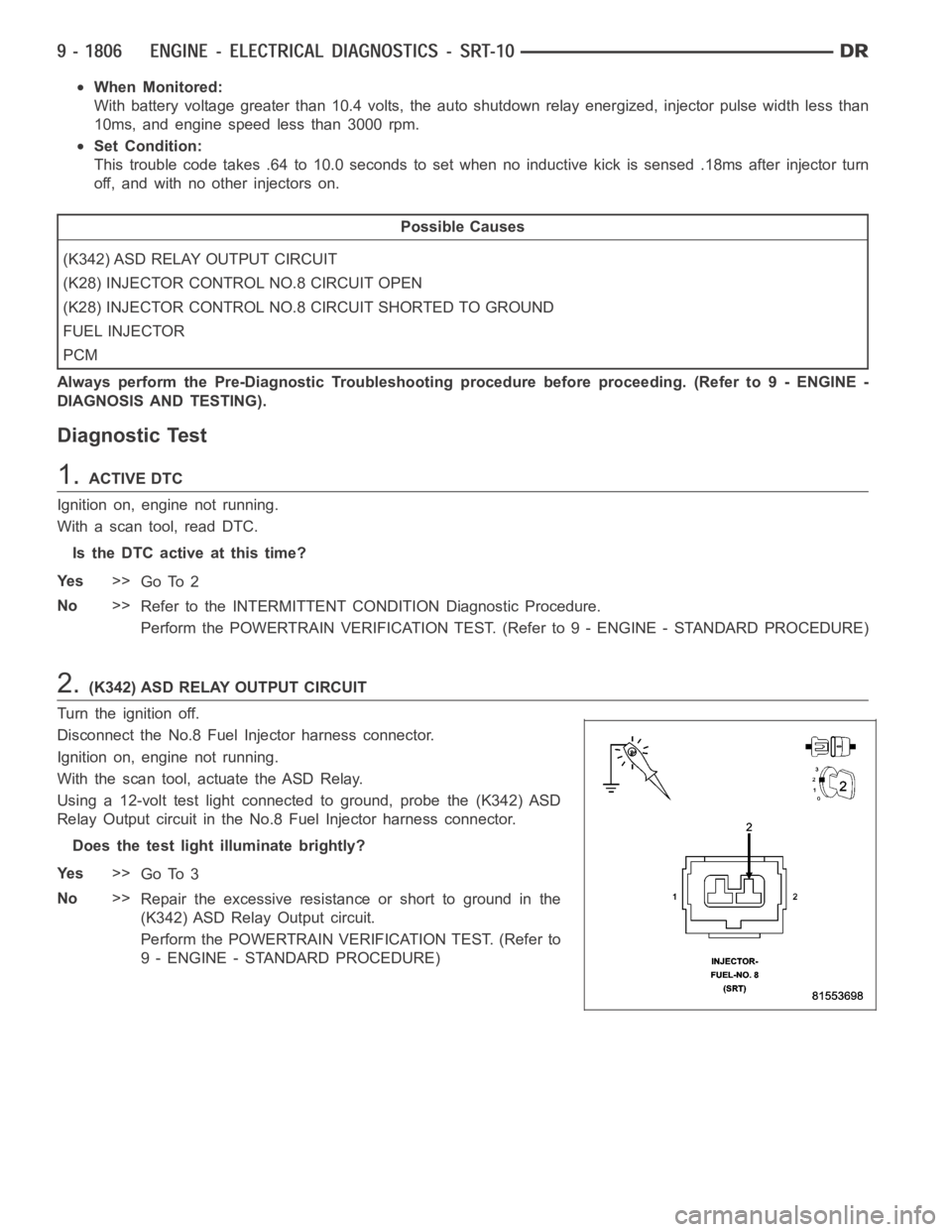
Disconnect the No.8 Fuel Injector harness connector.
Ignition on, engine not running.
With the scan tool, actuate the ASD Relay.
Using a 12-volt test light connected to ground, probe the (K342) ASD
Relay Output circuit in the No.8 Fuel Injector harness connector.
Does the test light illuminate brightly?
Ye s>>
Go To 3
No>>
Repair the excessive resistanceorshorttogroundinthe
(K342) ASD Relay Output circuit.
Perform the POWERTRAIN VERIFICATION TEST. (Refer to
9 - ENGINE - STANDARD PROCEDURE)
Page 1119 of 5267
When Monitored:
With battery voltage greater than 10.4 volts, the auto shutdown relay energized, injector pulse width less than
10ms, and engine speed less than 3000 rpm.
Set Condition:
This trouble code takes .64 to 10.0 seconds to set when no inductive kick is sensed .18ms after injector turn
off, and with no other injectors on.
Possible Causes
(K342) ASD RELAY OUTPUT CIRCUIT
(K115) INJECTOR CONTROL NO.9 CIRCUIT OPEN
(K115) INJECTOR CONTROL NO.9 CIRCUIT SHORTED TO GROUND
FUEL INJECTOR
PCM
Always perform the Pre-Diagnostic Troubleshooting procedure before proceeding. (Refer to 9 - ENGINE -
DIAGNOSIS AND TESTING).
Diagnostic Test
1.ACTIVE DTC
Ignition on, engine not running.
With a scan tool, read DTC.
Is the DTC active at this time?
Ye s>>
Go To 2
No>>
Refer to the INTERMITTENT CONDITION Diagnostic Procedure.
Perform the POWERTRAIN VERIFICATION TEST. (Refer to 9 - ENGINE - STANDARD PROCEDURE)
2.(K342) ASD RELAY OUTPUT CIRCUIT
Turn the ignition off.
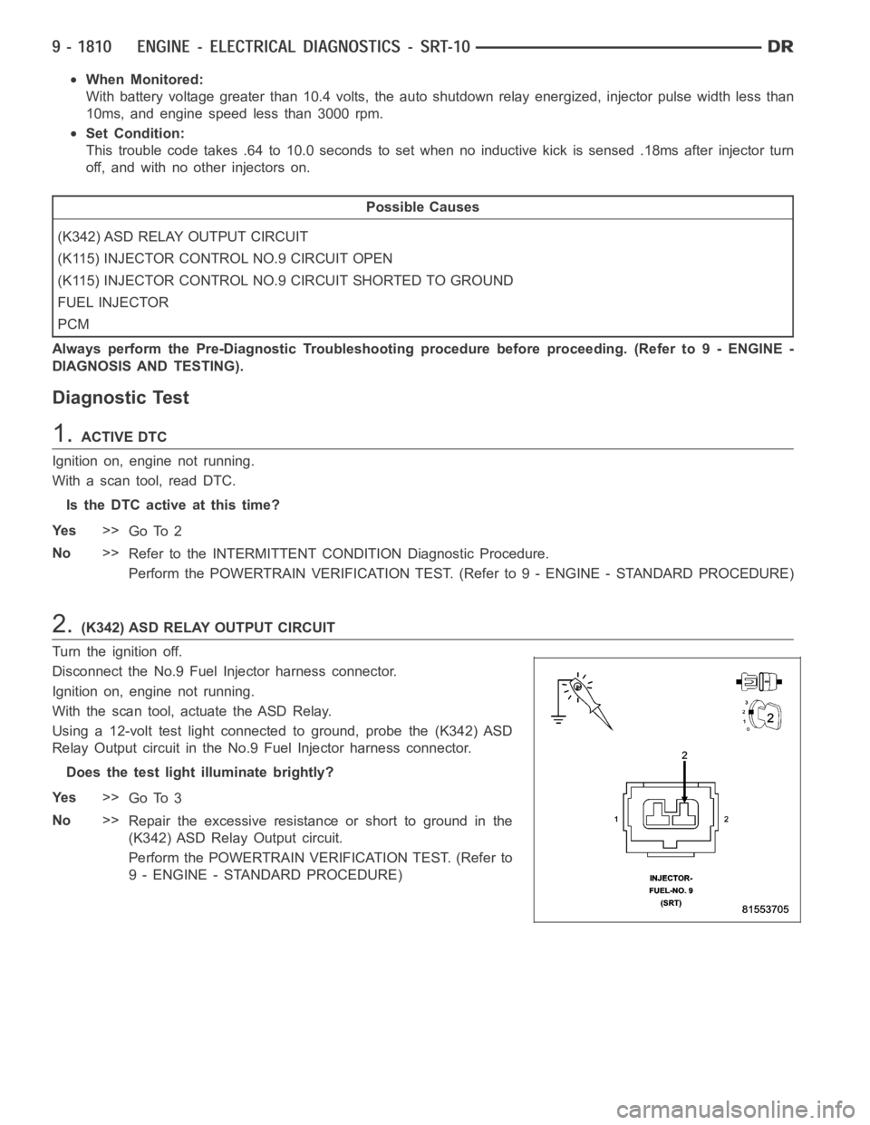
Disconnect the No.9 Fuel Injector harness connector.
Ignition on, engine not running.
With the scan tool, actuate the ASD Relay.
Using a 12-volt test light connected to ground, probe the (K342) ASD
Relay Output circuit in the No.9 Fuel Injector harness connector.
Does the test light illuminate brightly?
Ye s>>
Go To 3
No>>
Repair the excessive resistanceorshorttogroundinthe
(K342) ASD Relay Output circuit.
Perform the POWERTRAIN VERIFICATION TEST. (Refer to
9 - ENGINE - STANDARD PROCEDURE)
Page 1123 of 5267
When Monitored:
With battery voltage greater than 10.4 volts, the auto shutdown relay energized, injector pulse width less than
10ms, and engine speed less than 3000 rpm.
Set Condition:
This trouble code takes .64 to 10.0 seconds to set when no inductive kick is sensed .18ms after injector turn
off, and with no other injectors on.
Possible Causes
(K342) ASD RELAY OUTPUT CIRCUIT
(K116) INJECTOR CONTROL NO.10 CIRCUIT OPEN
(K116) INJECTOR CONTROL NO.10 CIRCUIT SHORTED TO GROUND
FUEL INJECTOR
PCM
Always perform the Pre-Diagnostic Troubleshooting procedure before proceeding. (Refer to 9 - ENGINE -
DIAGNOSIS AND TESTING).
Diagnostic Test
1.ACTIVE DTC
Ignition on, engine not running.
With a scan tool, read DTC.
Is the DTC active at this time?
Ye s>>
Go To 2
No>>
Refer to the INTERMITTENT CONDITION Diagnostic Procedure.
Perform the POWERTRAIN VERIFICATION TEST. (Refer to 9 - ENGINE - STANDARD PROCEDURE)
2.(K342) ASD RELAY OUTPUT CIRCUIT
Turn the ignition off.
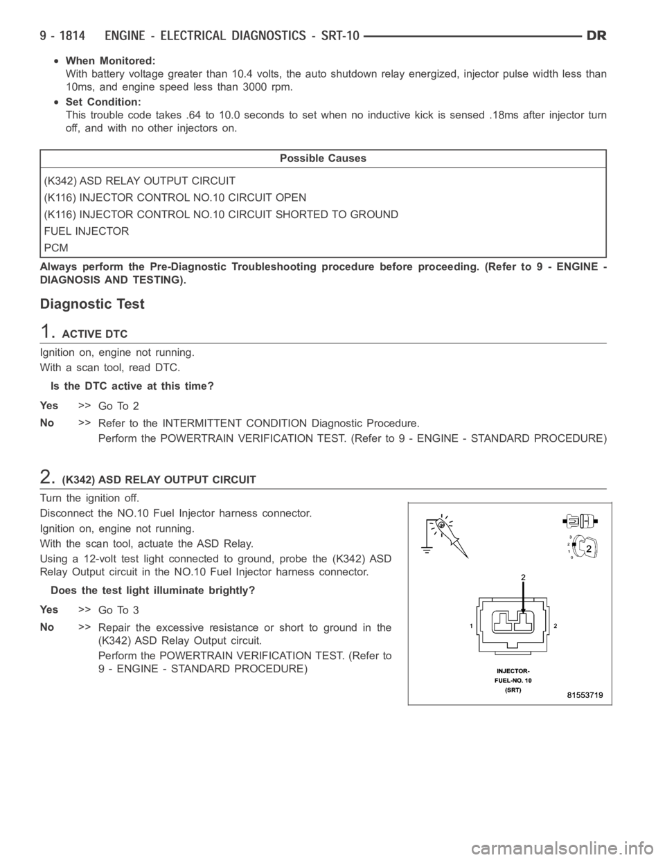
Disconnect the NO.10 Fuel Injector harness connector.
Ignition on, engine not running.
With the scan tool, actuate the ASD Relay.
Using a 12-volt test light connected to ground, probe the (K342) ASD
Relay Output circuit in the NO.10 Fuel Injector harness connector.
Does the test light illuminate brightly?
Ye s>>
Go To 3
No>>
Repair the excessive resistanceorshorttogroundinthe
(K342) ASD Relay Output circuit.
Perform the POWERTRAIN VERIFICATION TEST. (Refer to
9 - ENGINE - STANDARD PROCEDURE)
Page 1413 of 5267
P1398-MIS-FIRE ADAPTIVE NUMERATOR AT LIMIT
For a complete wiring diagramRefer to Section 8W.
When Monitored:
Under closed throttle decel and Fuel Pulse Width equal to zero for 30 seconds.
Set Condition:
One of the CKP sensor target windows has more than 2.86% variance from the reference window.
Possible Causes
ADAPTIVE NUMERATOR RELEARN
CMP SENSOR CONNECTOR/WIRING
CKP SENSOR CONNECTOR/WIRING
DAMAGED TONE WHEEL/FLEX PLATE (CRANKSHAFT)
CRANKSHAFT POSITION SENSOR
PCM
Always perform the Pre-Diagnostic Troubleshooting procedure before proceeding. (Refer to 9 - ENGINE -
DIAGNOSIS AND TESTING)
1.ADAPTIVE NUMERATOR RELEARN
NOTE: Check for any TSB’s that may apply to this symptom.
Read and record the Freeze Frame Data. Use this information to help you duplicate the conditions that set the DTC.
Pay particular attention to the DTC set conditions, such as, VSS, MAP, ECT,and Load.
Ignition on, engine not running.
With the scan tool in the miscellaneous menu, choose Clear PCM (battery disconnect) to reset the PCM.
With the scan tool, choose the Misfire Pretest screen.
Road test the vehicle and re-learn the adaptive numerator.
The adaptive numerator is learned when the Adaptive Numerator Done Learning line on the Misfire screen changes
to Yes.
Did the adaptive numerator re-learn?
Ye s>>
Refer to the INTERMITTENT CONDITIONSymptom (Diagnostic Procedure).
Perform POWERTRAIN VERIFICATION TEST. (Refer to 9 - ENGINE - STANDARD PROCEDURE)
No>>
Go To 2
2.CMP CONNECTOR/HARNESS INSPECTION
Turn ignition off.
NOTE: Visually inspect the related wire harness connectors. Look for broken, bent, pushed out, or corroded
terminals.
NOTE: Visually inspect the related wire harness. Look for any chafed, pierced, pinched, or partially broken
wires.
NOTE: Make sure the Camshaft Position Sensor is tight.
NOTE: Refer to any technical service bulletins that may apply.
Were any problems found?
Ye s>>
Repair as necessary.
Perform POWERTRAIN VERIFICATION TEST. (Refer to 9 - ENGINE - STANDARD PROCEDURE)
No>>
Go To 3
Page 1495 of 5267
Refer to CYLINDER COMBUSTION PRESSURE LEAKAGE DIAGNOSIS CHART .
CYLINDER COMBUSTION PRESSURE LEAKAGE DIAGNOSIS CHART
CONDITION POSSIBLE CAUSE CORRECTION
AIR ESCAPES THROUGH
THROTTLE BODYIntake valve bent, burnt, or not
seated properlyInspect valve and valve seat.
Reface or replace, as necessary.
Inspect valve springs. Replace as
necessary.
AIR ESCAPES THROUGH
TAILPIPEExhaust valve bent, burnt, or not
seated properlyInspect valve and valve seat.
Reface or replace, as necessary.
Inspect valve springs. Replace as
necessary.
AIR ESCAPES THROUGH
RADIATORHead gasket leaking or cracked
cylinder head or blockRemove cylinder head and inspect.
Replace defective part
MORE THAN 50% LEAKAGE
FROM ADJACENT CYLINDERSHead gasket leaking or crack in
cylinder head or block between
adjacent cylindersRemove cylinder head and inspect.
Replace gasket, head, or block as
necessary
MORE THAN 25% LEAKAGE AND
AIR ESCAPES THROUGH OIL
FILLER CAP OPENING ONLYStuckorbrokenpistonrings;
cracked piston; worn rings and/or
cylinder wallInspect for broken rings or piston.
Measure ring gap and cylinder
diameter, taper and out-of-round.
Replace defective part as necessary
STANDARD PROCEDURE
STANDARD PROCEDURE - REPAIR DAMAGED OR WORN THREADS
CAUTION: Be sure that the tapped holes maintain the original center line.
Damaged or worn threads can be repaired. Essentially, this repair consistsof:
Drilling out worn or damaged threads.
Tapping the hole with a special Heli-Coil Tap, or equivalent.
Installing an insert into the tapped hole to bring the hole back to its original thread size.
STANDARD PROCEDURE - FORM-IN-PLACE GASKETS AND SEALERS
There are numerous places where form-in-place gaskets are used on the engine. Care must be taken when apply-
ing form-in-place gaskets to assure obtaining the desired results.Do not use form-in-place gasket material
unless specified.Bead size, continuity, and location are of great importance. Too thin a bead can result in leakage
while too much can result in spill-overwhich can break off and obstruct fluid feed lines. A continuous bead of the
proper width is essential to obtain a leak-free gasket.
There are numerous types of form-in-place gasket materials that are used in the engine area. Mopar
Engine RTV
GEN II, Mopar
ATF-RTV, and MoparGasket Maker gasket materials, each have different properties and can not
be used in place of the other.
MOPAR
ENGINE RTV GEN II
Mopar
Engine RTV GEN II is used to seal components exposed to engine oil. This material is a specially designed
black silicone rubber RTV that retains adhesion and sealing properties when exposed to engine oil. Moisture in the
air causes the material to cure. This material is available in three ounce tubes and has a shelf life of one year. After
one year this material will not properly cure. Always inspect the package for the expiration date before use.
MOPAR
AT F R T V
Mopar
ATF RTV is a specifically designed black silicone rubber RTV that retains adhesion and sealing properties
to seal components exposed to automatic transmission fluid, engine coolants, and moisture. This material is avail-
able in three ounce tubes and has a shelf life of one year. After one year thismaterial will not properly cure. Always
inspect the package for the expiration date before use.
MOPAR
GASKET MAKER