2006 DODGE RAM SRT-10 width
[x] Cancel search: widthPage 4329 of 5267
WHEEL DESIGN
The rim size is on the vehicle safety certification label
located on the drivers door shut face. The size of the
rim is determined by the drivetrain package. Original
equipment wheels/rims are designed for operation up
to the specified maximum vehicle capacity.
All models use stamped steel, cast aluminum or
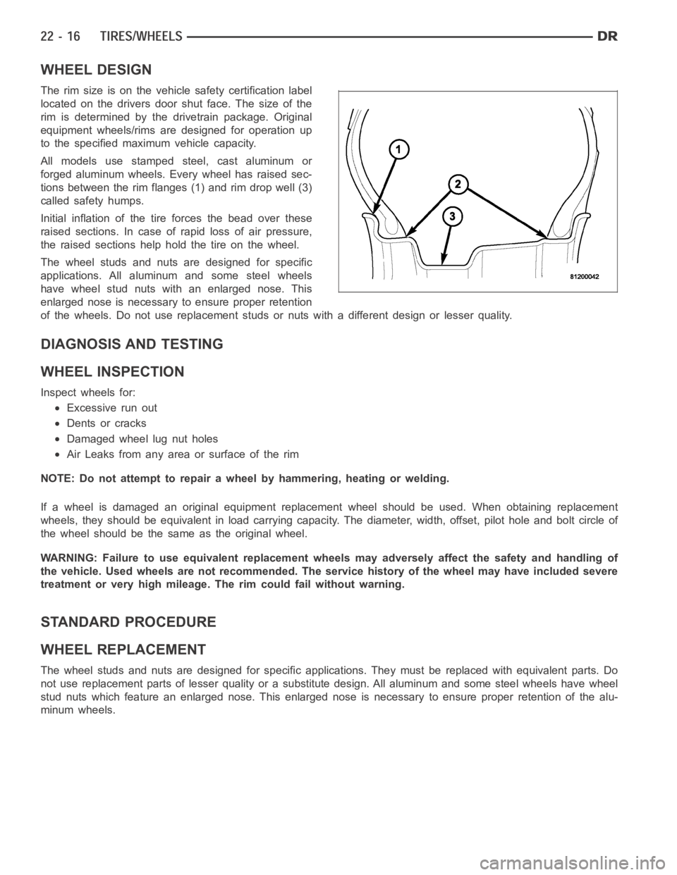
forged aluminum wheels. Every wheel has raised sec-
tions between the rim flanges (1) and rim drop well (3)
called safety humps.
Initial inflation of the tire forces the bead over these
raised sections. In case of rapid loss of air pressure,
the raised sections help hold the tire on the wheel.
The wheel studs and nuts are designed for specific
applications. All aluminum and some steel wheels
have wheel stud nuts with an enlarged nose. This
enlarged nose is necessary to ensure proper retention
of the wheels. Do not use replacement studs or nuts with a different design orlesserquality.
DIAGNOSIS AND TESTING
WHEEL INSPECTION
Inspect wheels for:
Excessive run out
Dents or cracks
Damaged wheel lug nut holes
Air Leaks from any area or surface of the rim
NOTE: Do not attempt to repair a wheel by hammering, heating or welding.
If a wheel is damaged an original equipment replacement wheel should be used. When obtaining replacement
wheels, they should be equivalent in load carrying capacity. The diameter, width, offset, pilot hole and bolt circle of
the wheel should be the same as the original wheel.
WARNING: Failure to use equivalent replacement wheels may adversely affect the safety and handling of
the vehicle. Used wheels are not recommended. The service history of the wheel may have included severe
treatment or very high mileage. The rim could fail without warning.
STANDARD PROCEDURE
WHEEL REPLACEMENT
The wheel studs and nuts are designed for specific applications. They mustbe replaced with equivalent parts. Do
not use replacement parts of lesser quality or a substitute design. All aluminum and some steel wheels have wheel
stud nuts which feature an enlarged nose. This enlarged nose is necessary to ensure proper retention of the alu-
minum wheels.
Page 4331 of 5267
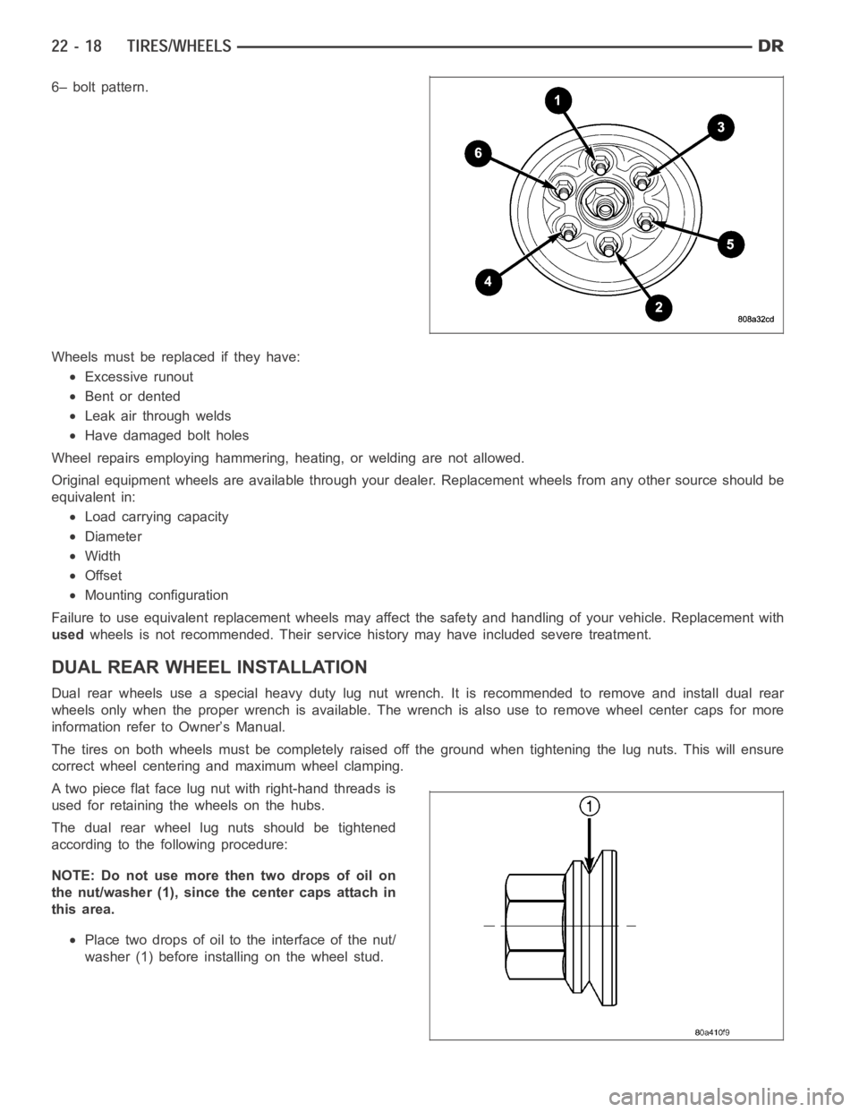
6– bolt pattern.
Wheels must be replaced if they have:
Excessive runout
Bent or dented
Leak air through welds
Have damaged bolt holes
Wheel repairs employing hammering, heating, or welding are not allowed.
Original equipment wheels are available through your dealer. Replacement wheels from any other source should be
equivalent in:
Load carrying capacity
Diameter
Width
Offset
Mounting configuration
Failure to use equivalent replacement wheels may affect the safety and handling of your vehicle. Replacement with
usedwheels is not recommended. Their service history may have included severetreatment.
DUAL REAR WHEELINSTALLATION
Dual rear wheels use a special heavy duty lug nut wrench. It is recommended to remove and install dual rear
wheels only when the proper wrench is available. The wrench is also use to remove wheel center caps for more
information refer to Owner’s Manual.
The tires on both wheels must be completely raised off the ground when tightening the lug nuts. This will ensure
correct wheel centering and maximum wheel clamping.
A two piece flat face lug nut with right-hand threads is
used for retaining the wheels on the hubs.
The dual rear wheel lug nuts should be tightened
according to the following procedure:
NOTE: Do not use more then two drops of oil on
the nut/washer (1), since the center caps attach in
this area.
Place two drops of oil to the interface of the nut/
washer (1) before installing on the wheel stud.
Page 5194 of 5267
The following is a list of the system monitors:
Misfire Monitor
Fuel System Monitor
Oxygen Sensor Monitor
Oxygen Sensor Heater Monitor
Catalyst Monitor
Leak Detection Pump Monitor (if equipped)
All these system monitors require two consecutive trips with the malfunction present to set a fault.
Refer to the appropriate Powertrain Diagnostics Procedures manual for diagnostic procedures.
The following is an operation and description of each system monitor:
OXYGEN SENSOR (O2S) MONITOR
Effective control of exhaust emissions is achieved by an oxygen feedback system. The most important element of
the feedback system is the O2S. The O2S is located in the exhaust path. Once it reaches operating temperature
300° to 350°C (572° to 662°F), the sensor generates a voltage that is inversely proportional to the amount of oxy-
gen in the exhaust. The information obtained by the sensor is used to calculate the fuel injector pulse width. This
maintains a 14.7 to 1 Air Fuel (A/F) ratio. At this mixture ratio, the catalyst works best to remove hydrocarbons (HC),
carbon monoxide (CO) and nitrogen oxide (NOx) from the exhaust.
The O2S is also the main sensing element for the Catalyst and Fuel Monitors.
The O2S can fail in any or all of the following manners:
slow response rate
reduced output voltage
dynamic shift
shortedoropencircuits
Response rate is the time required for the sensor to switch from lean to richonce it is exposed to a richer than
optimum A/F mixture or vice versa. As the sensor starts malfunctioning, itcould take longer to detect the changes
in the oxygen content of the exhaust gas.
The output voltage of the O2S ranges from 0 to 1 volt. A good sensor can easilygenerate any output voltage in this
range as it is exposed to different concentrations of oxygen. To detect a shift in the A/F mixture (lean or rich), the
output voltage has to change beyond a threshold value. A malfunctioning sensor could have difficulty changing
beyond the threshold value.
OXYGEN SENSOR HEATER MONITOR
If there is an oxygen sensor (O2S) shorted to voltage DTC, as well as a O2S heater DTC, the O2S fault MUST be
repaired first. Before checking the O2S fault, verify that the heater circuit is operating correctly.
Effective control of exhaust emissions is achieved by an oxygen feedback system. The most important element of
the feedback system is the O2S. The O2S is located in the exhaust path. Once it reaches operating temperature
300°C to 350°C (572°F to 662°F), the sensor generates a voltage that is inversely proportional to the amount of
oxygen in the exhaust. The information obtained by the sensor is used to calculate the fuel injector pulse width. This
maintains a 14.7 to 1 Air Fuel (A/F) ratio. At this mixture ratio, the catalyst works best to remove hydrocarbons (HC),
carbon monoxide (CO) and nitrogen oxide (NOx) from the exhaust.
The voltage readings taken from the O2S sensor are very temperature sensitive. The readings are not accurate
below 572°F (300°C). Heating of the O2S sensor is done to allow the engine controllertoshifttoclosedloopcontrol
as soon as possible. The heating element used to heat the O2S sensor must be testedtoensurethatitisheating
the sensor properly.
The O2S sensor circuit is monitored for a drop in voltage. The sensor outputis used to test the heater by isolating
the effect of the heater element on the O2S sensor output voltage from the other effects.
LEAK DETECTION PUMP MONITOR (IF EQUIPPED)
The leak detection assembly incorporates two primary functions: it must detect a leak in the evaporative system and
seal the evaporative system so the leak detection test can be run.
Page 5195 of 5267
The primary components within the assembly are: A three port solenoid thatactivates both of the functions listed
above; a pump which contains a switch, two check valves and a spring/diaphragm, a canister vent valve (CVV) seal
which contains a spring loaded vent seal valve.
Immediately after a cold start, between predetermined temperature thresholds limits, the three port solenoid is briefly
energized. This initializes the pump by drawing air into the pump cavity and also closes the vent seal. During non
test conditions the vent seal is held open by the pump diaphragm assembly which pushes it open at the full travel
position. The vent seal will remain closed while the pump is cycling due to the reed switch triggering of the three
port solenoid that prevents the diaphragm assembly from reaching full travel. After the brief initialization period, the
solenoid is de-energized allowing atmospheric pressure to enter the pumpcavity, thus permitting the spring to drive
the diaphragm which forces air out of the pump cavity and into the vent system. When the solenoid is energized
and de energized, the cycle is repeated creating flow in typical diaphragmpump fashion. The pump is controlled in
2 modes:
Pump Mode: The pump is cycled at a fixed rate to achieve a rapid pressure build in order to shorten the overall test
length.
Test Mode: The solenoid is energized with a fixed duration pulse. Subsequent fixed pulses occur when the dia-
phragm reaches the Switch closure point.
The spring in the pump is set so that the system will achieve an equalized pressure of about 7.5” H20. The cycle
rate of pump strokes is quite rapid as the system begins to pump up to this pressure. As the pressure increases, the
cycle rate starts to drop off. If there is no leak in the system, the pump would eventually stop pumping at the equal-
ized pressure. If there is a leak, it will continue to pump at a rate representative of the flow characteristic of the size
of the leak. From this information we can determine if the leak is larger than the required detection limit (currently
set at .040” orifice by CARB). If a leak is revealed during the leak test portion of the test, the test is terminated at
the end of the test mode and no further system checks will be performed.
After passing the leak detection phase of the test, system pressure is maintained by turning on the LDP’s solenoid
until the purge system is activated. Purge activation in effect creates a leak. The cycle rate is again interrogated and
when it increases due to the flow through the purge system, the leak check portion of the diagnostic is complete.
The canister vent valve will unseal the system after completion of the testsequence as the pump diaphragm assem-
bly moves to the full travel position.
Evaporative system functionality will be verified by using the stricter evap purge flow monitor. At an appropriate
warm idle the LDP will be energized to seal the canister vent. The purge flowwill be clocked up from some small
value in an attempt to see a shift in the02 control system. If fuel vapor, indicated by a shift in the 02 control, is
present the test is passed. If not, it is assumed that the purge system is notfunctioning in some respect. The LDP
is again turned off and the test is ended.
MISFIRE MONITOR
Excessive engine misfire results in increased catalyst temperature and causes an increase in HC emissions. Severe
misfires could cause catalyst damage. To prevent catalytic convertor damage, the PCM monitors engine misfire.
The Powertrain Control Module (PCM) monitors for misfire during most engine operating conditions (positive torque)
by looking at changes in the crankshaft speed. If a misfire occurs the speedof the crankshaft will vary more than
normal.
FUEL SYSTEM MONITOR
To comply with clean air regulations, vehicles are equipped with catalytic converters. These converters reduce the
emission of hydrocarbons, oxides of nitrogen and carbon monoxide. The catalyst works best when the Air Fuel (A/F)
ratio is at or near the optimum of 14.7 to 1.
The PCM is programmed to maintain the optimum air/fuel ratio of 14.7 to 1. This is done by making short term
corrections in the fuel injector pulse width based on the O2S sensor output. The programmed memory acts as a self
calibration tool that the engine controller uses to compensate for variations in engine specifications, sensor toler-
ances and engine fatigue over the life span of the engine. By monitoring theactual fuel-air ratio with the O2S sen-
sor (short term) and multiplying that with the program long-term (adaptive) memory and comparing that to the limit,
it can be determined whether it will pass an emissions test. If a malfunction occurs such that the PCM cannot main-
tain the optimum A/F ratio, then the MIL will be illuminated.
Page 5205 of 5267
SOLENOID-EVAP/PURGE
DESCRIPTION
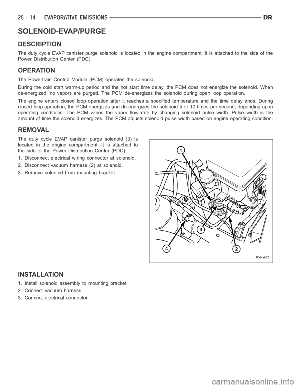
The duty cycle EVAP canister purge solenoid is located in the engine compartment. It is attached to the side of the
Power Distribution Center (PDC).
OPERATION
The Powertrain Control Module (PCM) operates the solenoid.
During the cold start warm-up period and the hot start time delay, the PCM does not energize the solenoid. When
de-energized, no vapors are purged. The PCM de-energizes the solenoid during open loop operation.
The engine enters closed loop operation after it reaches a specified temperature and the time delay ends. During
closed loop operation, the PCM energizes and de-energizes the solenoid 5 or 10 times per second, depending upon
operating conditions. The PCM varies the vapor flow rate by changing solenoid pulse width. Pulse width is the
amount of time the solenoid energizes. The PCM adjusts solenoid pulse width based on engine operating condition.
REMOVAL
The duty cycle EVAP canister purge solenoid (3) is
located in the engine compartment. It is attached to
the side of the Power Distribution Center (PDC).
1. Disconnect electrical wiring connector at solenoid.
2. Disconnect vacuum harness (2) at solenoid.
3. Remove solenoid from mounting bracket.
INSTALLATION
1. Install solenoid assembly to mounting bracket.
2. Connect vacuum harness.
3. Connect electrical connector.