2006 DODGE RAM SRT-10 transmission fluid
[x] Cancel search: transmission fluidPage 3430 of 5267
FLUID AND FILTER
DIAGNOSIS AND TESTING
EFFECTS OF INCORRECT FLUID LEVEL
Alowfluidlevelallowsthepumptotakeinairalongwiththefluid.Airinthe fluid will cause fluid pressures to be
low and develop slower than normal. If the transmission is overfilled, thegears churn the fluid into foam. This aer-
ates the fluid and causing the same conditions occurring with a low level. In either case, air bubbles cause fluid
overheating, oxidation, and varnish buildup which interferes with valveand clutch operation. Foaming also causes
fluid expansion which can result in fluid overflow from the transmission vent or fill tube. Fluid overflow can easily be
mistaken for a leak if inspection is not careful.
CAUSES OF BURNT FLUID
Burnt, discolored fluid is a result of overheating which has three primarycauses.
1. Internal clutch slippage, usually caused by low line pressure, inadequate clutch apply pressure, or clutch seal
failure.
2. A result of restricted fluid flow through the main and/or auxiliary cooler. This condition is usually the result of a
faulty or improperly installed drainback valve, a damaged oil cooler, or severe restrictions in the coolers and lines
caused by debris or kinked lines.
3. Heavy duty operation with a vehicle not properly equipped for this type of operation. Trailer towing or similar high
load operation will overheat the transmission fluid if the vehicle is improperly equipped. Such vehicles should
have an auxiliary transmission fluid cooler, a heavy duty cooling system,and the engine/axle ratio combination
needed to handle heavy loads.
FLUID CONTAMINATION
Transmission fluid contamination is generally a result of:
adding incorrect fluid
failure to clean dipstick and fill tube when checking level
engine coolant entering the fluid
internal failure that generates debris
overheat that generates sludge (fluid breakdown)
failure to replace contaminated converter after repair
The use of non-recommended fluids can result in transmission failure. Theusual results are erratic shifts, slippage,
abnormal wear and eventual failure due to fluid breakdown and sludge formation. Avoid this condition by using rec-
ommended fluids only.
The dipstick cap and fill tube should be wiped clean before checking fluid level. Dirt, grease and other foreign mate-
rial on the cap and tube could fall into the tube if not removed beforehand. Take the time to wipe the cap and tube
clean before withdrawing the dipstick.
Engine coolant in the transmission fluid is generally caused by a cooler malfunction. The only remedy is to replace
the radiator as the cooler in the radiator is not a serviceable part. If coolant has circulated through the transmission,
an overhaul is necessary.
The torque converter should also be replaced whenever a failure generatessludge and debris. This is necessary
because normal converter flushing procedures will not remove all contaminants.
STANDARD PROCEDURE
FLUID LEVEL CHECK
Low fluid level can cause a variety of conditions because it allows the pumpto take in air along with the fluid. As
in any hydraulic system, air bubbles make the fluid spongy, therefore, pressures will be low and build up slowly.
Improper filling can also raise the fluid level too high. When the transmssion has too much fluid, the geartrain
churns up foam and cause the same conditions which occur with a low fluid level.
Page 3431 of 5267

In either case, air bubbles can cause overheating and/or fluid oxidation,and varnishing. This can interfere with nor-
mal valve, clutch, and accumulator operation. Foaming can also result in fluid escaping from the transmission vent
where it may be mistaken for a leak.
After the fluid has been checked, seat the dipstick fully to seal out water and dirt.
The transmission has a dipstick to check oil level. It is located on the right side of the engine. Be sure to wipe all
dirt from dipstick handle before removing.
The torque converter fills in both the P(PARK) and N (NEUTRAL) positions. Place the selector lever in P (PARK)
to be sure that the fluid level check is accurate.The engine should be running at idle speed for at least one
minute, with the vehicle on level ground.At normal operating temperature (approximately 82° C. or 180° F), the
fluid level is correct if it is in the HOT region (cross-hatched area) on theoil level indicator. The fluid level will be
approximately at the upper COLD hole of the dipstick at 21° C (70° F) fluid temperature.
NOTE: Engine and Transmission should be at normal operating temperature before performing this proce-
dure.
1. Start engine and apply parking brake.
2. Shift the transmission into DRIVE for approximately 2 seconds.
3. Shift the transmission into REVERSE for approximately 2 seconds.
4. Shift the transmission into PARK.
5. Hook up scan tool andselect transmission.
6. Select sensors.
7. Read the transmission temperature value.
8. Compare the fluid temperature value with the chart.
9. Adjust transmission fluid level shown on the dipstick according to the Transmission Fluid Temperature Chart.
NOTE: After adding any fluid to the transmission, wait a minimum of 2 minutes for the oil to fully drain from
the fill tube into the transmission before rechecking the fluid level.
10. Check transmission for leaks.
Page 3432 of 5267
FLUID AND FILTER REPLACEMENT
For proper service intervals (Refer to LUBRICATION & MAINTENANCE/MAINTENANCE SCHEDULES - DESCRIP-
TION).
REMOVAL
1. Hoist and support vehicle on safety stands.
2. Place a large diameter shallow drain pan beneath the transmission pan.
3. Remove bolts holding front and sides of pan to transmission.
4. Loosen bolts holding rear of pan to transmission.
5. Slowly separate front of pan away from transmission allowing the fluid to drain into drain pan.
6. Hold up pan and remove remaining bolts holding pan to transmission.
7. While holding pan level, lower pan away from transmission.
8. Pour remaining fluid in pan into drain pan.
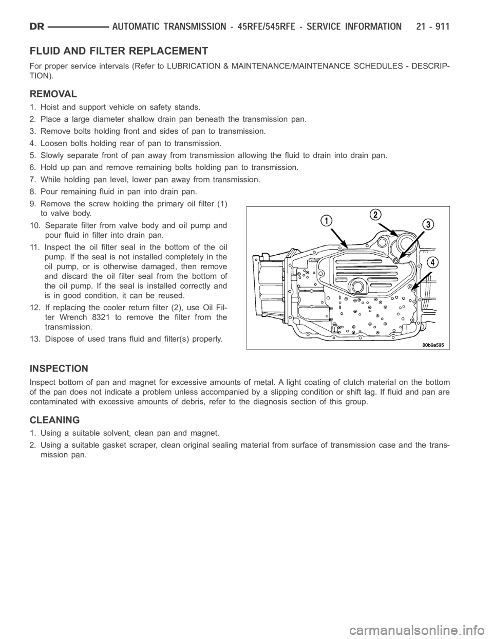
9. Remove the screw holding the primary oil filter (1)
to valve body.
10. Separate filter from valve body and oil pump and
pour fluid in filter into drain pan.
11. Inspect the oil filter seal in the bottom of the oil
pump. If the seal is not installed completely in the
oil pump, or is otherwise damaged, then remove
and discard the oil filter seal from the bottom of
the oil pump. If the seal is installed correctly and
is in good condition, it can be reused.
12. If replacing the cooler return filter (2), use Oil Fil-
ter Wrench 8321 to remove the filter from the
transmission.
13. Dispose of used trans fluid and filter(s) properly.
INSPECTION
Inspect bottom of pan and magnet for excessive amounts of metal. A light coating of clutch material on the bottom
of the pan does not indicate a problem unless accompanied by a slipping condition or shift lag. If fluid and pan are
contaminated with excessive amounts of debris, refer to the diagnosis section of this group.
CLEANING
1. Using a suitable solvent, clean pan and magnet.
2. Using a suitable gasket scraper, clean original sealing material from surface of transmission case and the trans-
mission pan.
Page 3433 of 5267
INSTALLATION
CAUTION: The primary oil filter seal MUST be fully
installed flush against the oil pump body. DO NOT
install the seal onto the filter neck and attempt to
install the filter and seal as an assembly. Damage
to the transmission will result.
1. If necessary, install a new primary oil filter seal in
the oil pump inlet bore. Seat the seal in the bore
with a suitable tool (appropriately sized drift or
socket, the butt end of a hammer, or other suitable
tool).
2. Place replacement filter in position on valve body
and into the oil pump.
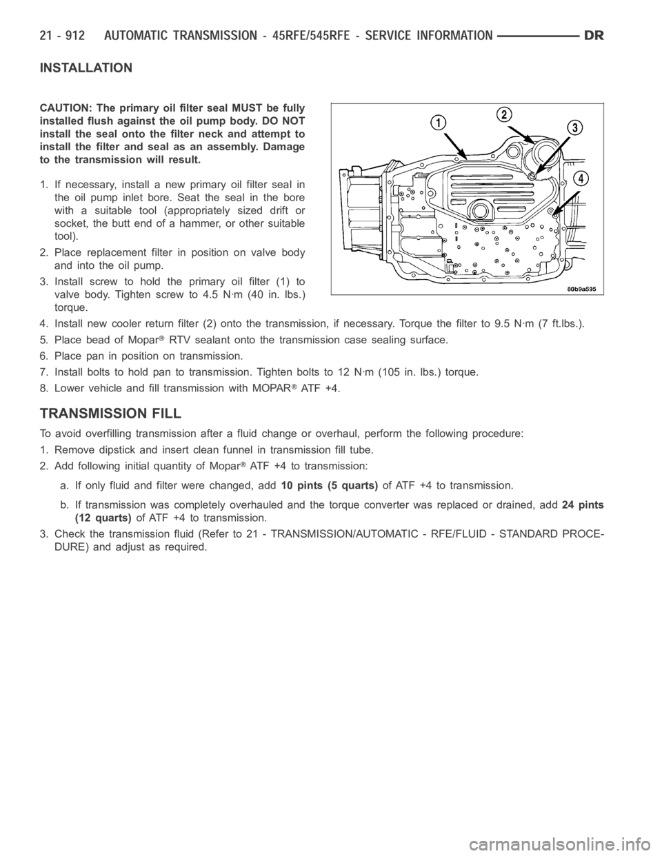
3. Install screw to hold the primary oil filter (1) to
valve body. Tighten screw to 4.5 Nꞏm (40 in. lbs.)
torque.
4. Install new cooler return filter (2) onto the transmission, if necessary. Torque the filter to 9.5 Nꞏm (7 ft.lbs.).
5. Place bead of Mopar
RTV sealant onto the transmission case sealing surface.
6. Place pan in position on transmission.
7. Install bolts to hold pan to transmission. Tighten bolts to 12 Nꞏm (105 in. lbs.) torque.
8. Lower vehicle and fill transmission with MOPAR
AT F + 4 .
TRANSMISSION FILL
To avoid overfilling transmission after a fluid change or overhaul, perform the following procedure:
1. Remove dipstick and insert clean funnel in transmission fill tube.
2. Add following initial quantity of Mopar
ATF+4totransmission:
a. If only fluid and filter were changed, add10 pints (5 quarts)of ATF +4 to transmission.
b. If transmission was completely overhauled and the torque converter wasreplaced or drained, add24 pints
(12 quarts)ofATF+4totransmission.
3. Check the transmission fluid (Refer to 21 - TRANSMISSION/AUTOMATIC - RFE/FLUID - STANDARD PROCE-
DURE) and adjust as required.
Page 3438 of 5267
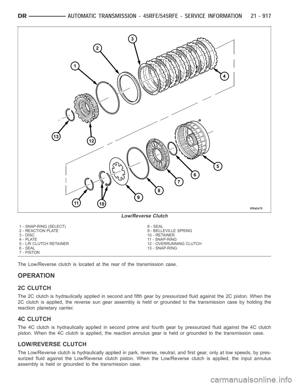
The Low/Reverse clutch is located at the rear of the transmission case.
OPERATION
2C CLUTCH
The 2C clutch is hydraulically applied in second and fifth gear by pressurized fluid against the 2C piston. When the
2C clutch is applied, the reverse sun gear assembly is held or grounded to the transmission case by holding the
reaction planetary carrier.
4C CLUTCH
The 4C clutch is hydraulically applied in second prime and fourth gear by pressurized fluid against the 4C clutch
piston. When the 4C clutch is applied, the reaction annulus gear is held or grounded to the transmission case.
LOW/REVERSE CLUTCH
The Low/Reverse clutch is hydraulically applied in park, reverse, neutral, and first gear, only at low speeds, by pres-
surized fluid against the Low/Reverse clutch piston. When the Low/Reverse clutch is applied, the input annulus
assembly is held or grounded to the transmission case.
Low/Reverse Clutch
1 - SNAP-RING (SELECT) 8 - SEAL
2 - REACTION PLATE 9 - BELLEVILLE SPRING
3 - DISC 10 - RETAINER
4 - PLATE 11 - SNAP-RING
5 - L/R CLUTCH RETAINER 12 - OVERRUNNING CLUTCH
6 - SEAL 13 - SNAP-RING
7-PISTON
Page 3441 of 5267
OPERATION
The three input clutches are responsible for driving different components of the planetary geartrain.
UNDERDRIVE CLUTCH
The underdrive clutch is hydraulically applied in first, second, second prime, and third (direct) gears by pressurized
fluid against the underdrive piston. When the underdrive clutch is applied, the underdrive hub drives the input sun
gear.
OVERDRIVE CLUTCH
The overdrive clutch is hydraulically applied in third (direct), fourth,and fifth gears by pressurized fluid against the
overdrive/reverse piston. When the overdrive clutch isapplied, the overdrive hub drives the reverse carrier/input
annulus assembly.
REVERSE CLUTCH
The reverse clutch is hydraulically applied in reverse gear by pressurized fluid against the overdrive/reverse piston.
When the reverse clutch is applied, the reaction annulus gear is driven.
DISASSEMBLY
NOTE: If the input clutch assembly is being reconditioned (clutch/seal replacement) or replaced, it is nec-
essary to perform the Quick Learn Procedure using the scan tool (Refer to 8 -ELECTRICAL/ELECTRONIC
CONTROL MODULES/TRANSMISSION CONTROL MODULE - STANDARD PROCEDURE).
Page 3446 of 5267
ASSEMBLY
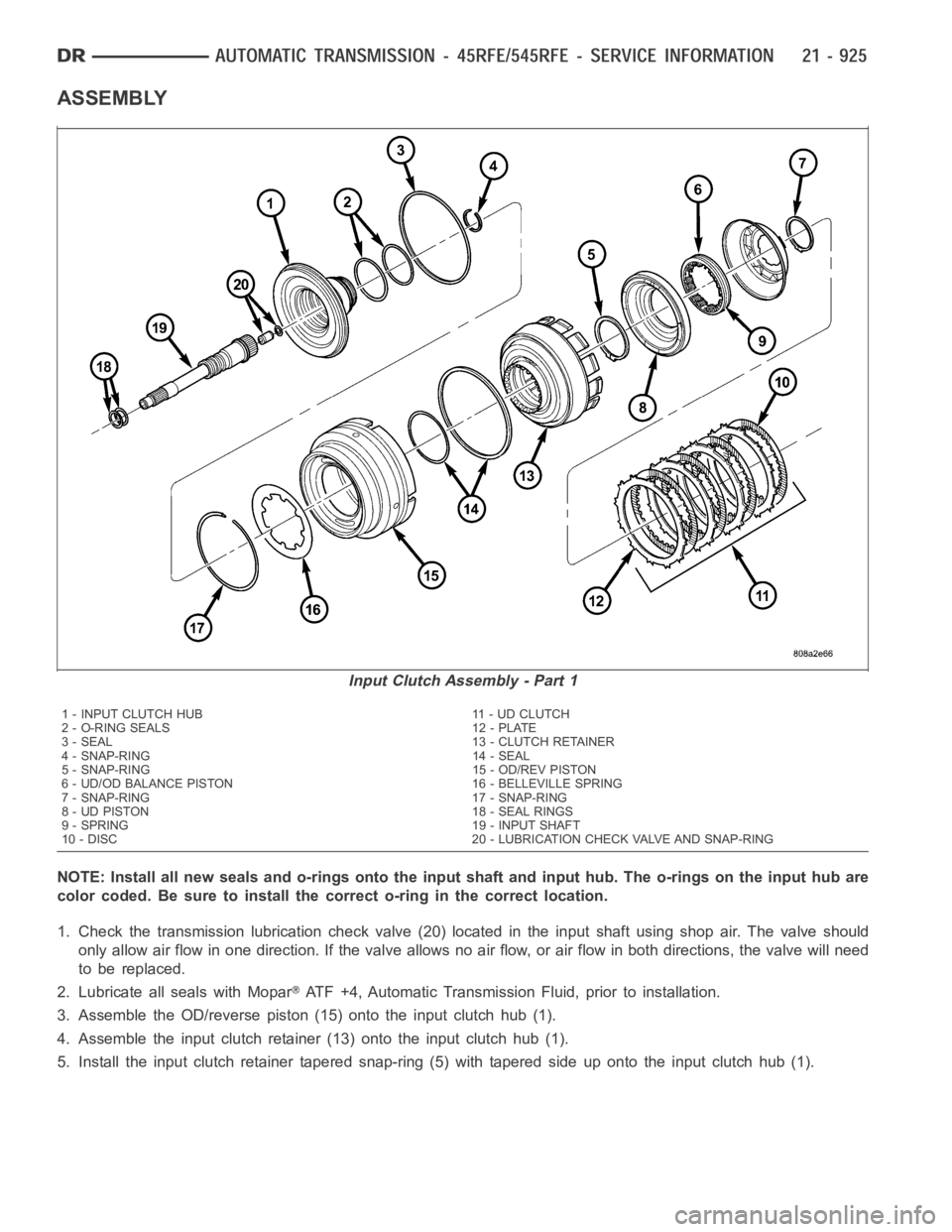
NOTE: Install all new seals and o-rings onto the input shaft and input hub. The o-rings on the input hub are
color coded. Be sure to install the correct o-ring in the correct location.
1. Check the transmission lubrication check valve (20) located in the input shaft using shop air. The valve should
only allow air flow in one direction. If the valve allows no air flow, or air flow in both directions, the valve will need
to be replaced.
2. Lubricate all seals with Mopar
ATF +4, Automatic Transmission Fluid, prior to installation.
3. Assemble the OD/reverse piston (15) onto the input clutch hub (1).
4. Assemble the input clutch retainer (13) onto the input clutch hub (1).
5. Install the input clutch retainer tapered snap-ring (5) with tapered side up onto the input clutch hub (1).
Input Clutch Assembly - Part 1
1 - INPUT CLUTCH HUB 11 - UD CLUTCH
2 - O-RING SEALS 12 - PLATE
3 - SEAL 13 - CLUTCH RETAINER
4 - SNAP-RING 14 - SEAL
5 - SNAP-RING 15 - OD/REV PISTON
6 - UD/OD BALANCE PISTON 16 - BELLEVILLE SPRING
7 - SNAP-RING 17 - SNAP-RING
8 - UD PISTON 18 - SEAL RINGS
9 - SPRING 19 - INPUT SHAFT
10 - DISC 20 - LUBRICATION CHECK VALVE AND SNAP-RING
Page 3453 of 5267
SENSOR-INPUT SPEED
DESCRIPTION
The Input and Output Speed Sensors are two-wire magnetic pickup devices that generate AC signals as rotation
occurs. They are mounted in the left side of the transmission case and are considered primary inputs to the Trans-
mission Control Module (TCM).
OPERATION
The Input Speed Sensor provides information on how fast the input shaft is rotating. As the teeth of the input clutch
hub pass by the sensor coil, an AC voltage is generated and sent to the TCM. The TCM interprets this information
as input shaft rpm.
The Output Speed Sensor generates an AC signal in a similar fashion, thoughitscoilisexcitedbyrotationofthe
rear planetary carrier lugs. The TCM interprets this information as outputshaftrpm.
The TCM compares the input and output speed signals to determine the following:
Transmission gear ratio
Speed ratio error detection
CVI calculation
The TCM also compares the input speed signal and the engine speed signal to determine the following:
Torque converter clutch slippage
Torque converter element speed ratio
REMOVAL
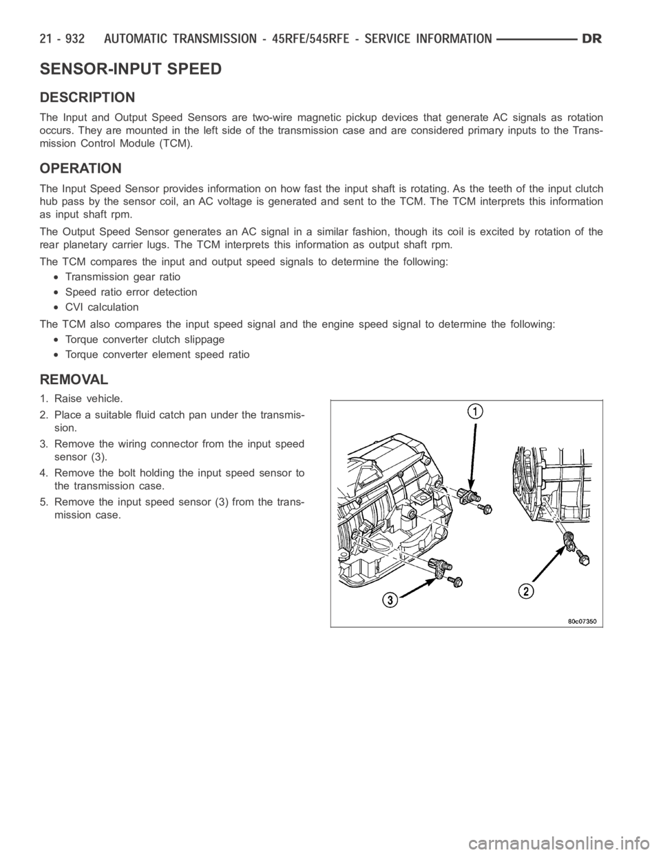
1. Raise vehicle.
2. Place a suitable fluid catch pan under the transmis-
sion.
3. Remove the wiring connector from the input speed
sensor (3).
4. Remove the bolt holding the input speed sensor to
the transmission case.
5. Remove the input speed sensor (3) from the trans-
mission case.