Page 3481 of 5267
VALVE-SOLENOID SWITCH
DESCRIPTION
The Solenoid Switch Valve (SSV) is located in the valve body and controls the direction of the transmission fluid
when the L/R-TCC solenoid is energized.
OPERATION
The Solenoid Switch Valve controls line pressure from the LR-TCC solenoid. In 1st gear, the SSV will be in the
downshifted position, thus directing fluid to the L/R clutch circuit. In 2nd, 3rd, 4th, and 5th (if applicable) gears, the
solenoid switch valve will be in the upshifted position and directs the fluid into the torque converter clutch (TCC)
circuit.
When shifting into 1st gear, a special hydraulic sequence is performed to ensure SSV movement into the down-
shifted position. The L/R pressure switch is monitored to confirm SSV movement. If the movement is not confirmed
(the L/R pressure switch does not close), 2nd gear is substituted for 1st. ADTC will be set after three unsuccessful
attempts are made to get into 1st gear in one given key start.
Page 3482 of 5267
CONVERTER-TORQUE
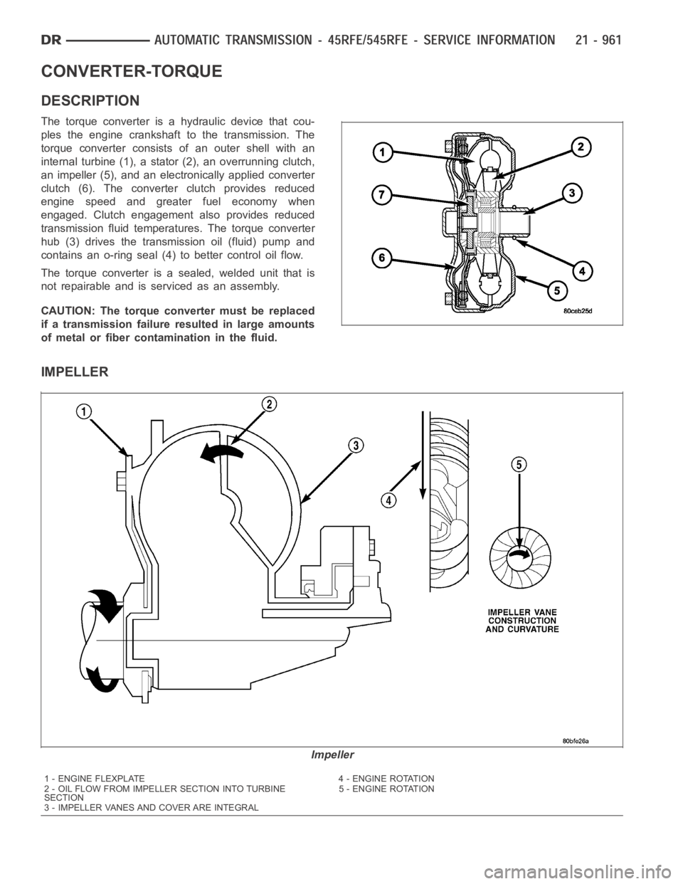
DESCRIPTION
The torque converter is a hydraulic device that cou-
ples the engine crankshaft to the transmission. The
torque converter consists of an outer shell with an
internal turbine (1), a stator (2), an overrunning clutch,
an impeller (5), and an electronically applied converter
clutch (6). The converterclutch provides reduced
engine speed and greater fuel economy when
engaged. Clutch engagement also provides reduced
transmission fluid temperatures. The torque converter
hub (3) drives the transmission oil (fluid) pump and
contains an o-ring seal (4) to better control oil flow.
The torque converter is a sealed, welded unit that is
not repairable and is serviced as an assembly.
CAUTION: The torque converter must be replaced
if a transmission failure resulted in large amounts
of metal or fiber contamination in the fluid.
IMPELLER
Impeller
1 - ENGINE FLEXPLATE 4 - ENGINE ROTATION
2 - OIL FLOW FROM IMPELLER SECTION INTO TURBINE
SECTION5 - ENGINE ROTATION
3 - IMPELLER VANES AND COVER ARE INTEGRAL
Page 3485 of 5267
TORQUE CONVERTER CLUTCH (TCC)
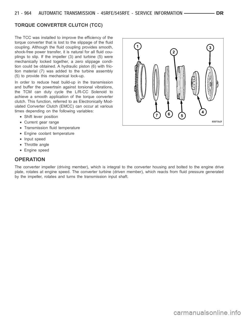
The TCC was installed to improve the efficiency of the
torque converter that is lost to the slippage of the fluid
coupling. Although the fluid coupling provides smooth,
shock-free power transfer, it is natural for all fluid cou-
plings to slip. If the impeller (3) and turbine (5) were
mechanically locked together, a zero slippage condi-
tion could be obtained. A hydraulic piston (6) with fric-
tion material (7) was added to the turbine assembly
(5) to provide this mechanical lock-up.
In order to reduce heat build-up in the transmission
and buffer the powertrain against torsional vibrations,
the TCM can duty cycle the L/R-CC Solenoid to
achieve a smooth application of the torque converter
clutch. This function, referred to as Electronically Mod-
ulated Converter Clutch (EMCC) can occur at various
times depending on the following variables:
Shift lever position
Current gear range
Transmission fluid temperature
Engine coolant temperature
Input speed
Throttle angle
Engine speed
OPERATION
The converter impeller (driving member), which is integral to the converter housing and bolted to the engine drive
plate, rotates at engine speed. The converter turbine (driven member), which reacts from fluid pressure generated
by the impeller, rotates and turns the transmission input shaft.
Page 3488 of 5267
4. Separate the torque converter from the transmission.
INSTALLATION
NOTE: Check converter hub and drive flats for sharp edges, burrs, scratches, or nicks. Polish the hub and
flats with 320/400 grit paper or crocus cloth if necessary. Verify that theconverter hub o-ring is properly
installed and is free from debris. The hub must be smooth to avoid damaging the pump seal at installation.
1. Lubricate oil pump seal lip with transmission fluid.
2. Place torque converter in position on transmission.
CAUTION: Do not damage oil pump seal or con-
verter hub o-ring while inserting torque converter
into the front of the transmission.
3. Align torque converter to oil pump seal opening.
4. Insert torque converter hub into oil pump.
5. While pushing torque converter inward, rotate con-
verter until converter is fully seated in the oil pump
gears.
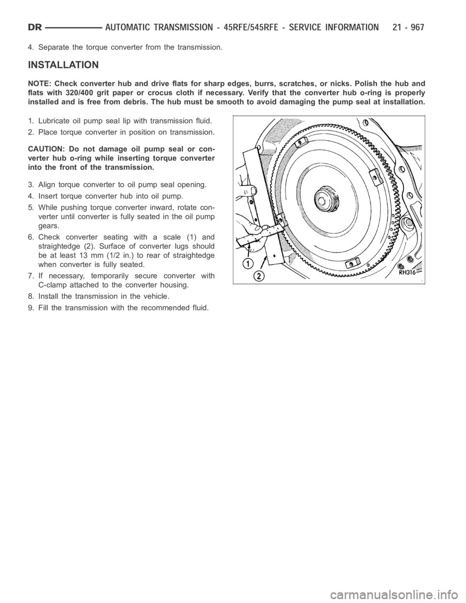
6. Check converter seating with a scale (1) and
straightedge (2). Surface of converter lugs should
be at least 13 mm (1/2 in.) to rear of straightedge
when converter is fully seated.
7. If necessary, temporarily secure converter with
C-clamp attached to the converter housing.
8. Install the transmission in the vehicle.
9. Fill the transmission with the recommended fluid.
Page 3491 of 5267
ASSEMBLY-TRANSMISSION SOLENOID/TRS
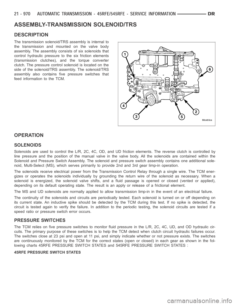
DESCRIPTION
The transmission solenoid/TRS assembly is internal to
the transmission and mounted on the valve body
assembly. The assembly consists of six solenoids that
control hydraulic pressure to the six friction elements
(transmission clutches), and the torque converter
clutch. The pressure control solenoid is located on the
side of the solenoid/TRS assembly. The solenoid/TRS
assembly also contains five pressure switches that
feed information to the TCM.
OPERATION
SOLENOIDS
Solenoids are used to control the L/R, 2C, 4C, OD, and UD friction elements.The reverse clutch is controlled by
line pressure and the position of the manual valve in the valve body. All thesolenoids are contained within the
Solenoid and Pressure Switch Assembly. The solenoid and pressure switch assembly contains one additional sole-
noid, Multi-Select (MS), which serves primarily to provide 2nd and 3rd gear limp-in operation.
The solenoids receive electrical power from the Transmission Control Relay through a single wire. The TCM ener-
gizes or operates the solenoids individually by grounding the return wireof the solenoid as necessary. When a
solenoid is energized, the solenoid valve shifts, and a fluid passage is opened or closed (vented or applied),
depending on its default operating state. The result is an apply or releaseof a frictional element.
The MS and UD solenoids are normallyapplied to allow transmission limp-inin the event of an electrical failure.
The continuity of the solenoids and circuits are periodically tested. Each solenoid is turned on or off depending on
its current state. An inductive spike should be detected by the TCM during this test. If no spike is detected, the
circuit is tested again to verify the failure. In addition to the periodic testing, the solenoid circuits are tested if a
speed ratio or pressure switch error occurs.
PRESSURE SWITCHES
The TCM relies on five pressure switches to monitor fluid pressure in the L/R, 2C, 4C, UD, and OD hydraulic cir-
cuits. The primary purpose of these switches is to help the TCM detect when clutch circuit hydraulic failures occur.
The switches close at 23 psi and open at 11 psi, and simply indicate whether or not pressure exists. The switches
are continuously monitored by the TCM for the correct states (open or closed) in each gear as shown in the fol-
lowing charts 45RFE PRESSURE SWITCH STATES and 545RFE PRESSURE SWITCH STATES :
45RFE PRESSURE SWITCH STATES
Page 3494 of 5267
SENSOR-TRANSMISSION TEMPERATURE
DESCRIPTION
The transmission temperature sensor is a thermistor that is integral to the Transmission Range Sensor (TRS).
OPERATION
The transmission temperature sensor is used by the TCM to sense the temperature of the fluid in the sump. Since
fluid temperature can affect transmission shift quality and convertor lock up, the TCM requires this information to
determine which shift schedule to operate in.
Calculated Temperature
A failure in the temperature sensor or circuit will result in calculated temperature being substituted for actual tem-
perature. Calculated temperature is a predicted fluid temperature whichis calculated from a combination of inputs:
Battery (ambient) temperature
Engine coolant temperature
In-gear run time since start-up
Page 3496 of 5267
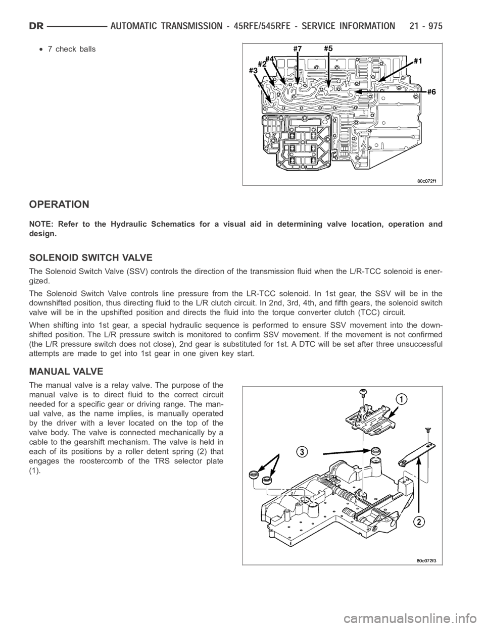
7 check balls
OPERATION
NOTE: Refer to the Hydraulic Schematics for a visual aid in determining valve location, operation and
design.
SOLENOID SWITCH VALVE
The Solenoid Switch Valve (SSV) controls the direction of the transmission fluid when the L/R-TCC solenoid is ener-
gized.
The Solenoid Switch Valve controls line pressure from the LR-TCC solenoid. In 1st gear, the SSV will be in the
downshifted position, thus directing fluid to the L/R clutch circuit. In 2nd, 3rd, 4th, and fifth gears, the solenoid switch
valve will be in the upshifted position and directs the fluid into the torque converter clutch (TCC) circuit.
When shifting into 1st gear, a special hydraulic sequence is performed to ensure SSV movement into the down-
shifted position. The L/R pressure switch is monitored to confirm SSV movement. If the movement is not confirmed
(the L/R pressure switch does not close), 2nd gear is substituted for 1st. ADTC will be set after three unsuccessful
attempts are made to get into 1st gear in one given key start.
MANUAL VALVE
The manual valve is a relay valve. The purpose of the
manual valve is to direct fluid to the correct circuit
needed for a specific gear or driving range. The man-
ual valve, as the name implies, is manually operated
by the driver with a lever located on the top of the
valve body. The valve is connected mechanically by a
cable to the gearshift mechanism. The valve is held in
each of its positions by a roller detent spring (2) that
engages the roostercomb of the TRS selector plate
(1).
Page 3503 of 5267
Inspect all the fluid seals on the valve body. Replace
any seals that are cracked, distorted, or damaged in
any way. These seals pass fluid pressure directly to
the clutches. Any pressure leak at these points, may
cause transmission performance problems.