2005 NISSAN NAVARA control unit
[x] Cancel search: control unitPage 1711 of 3171
POWER WINDOW SYSTEM
GW-25
C
D
E
F
G
H
J
K
L
MA
B
GW
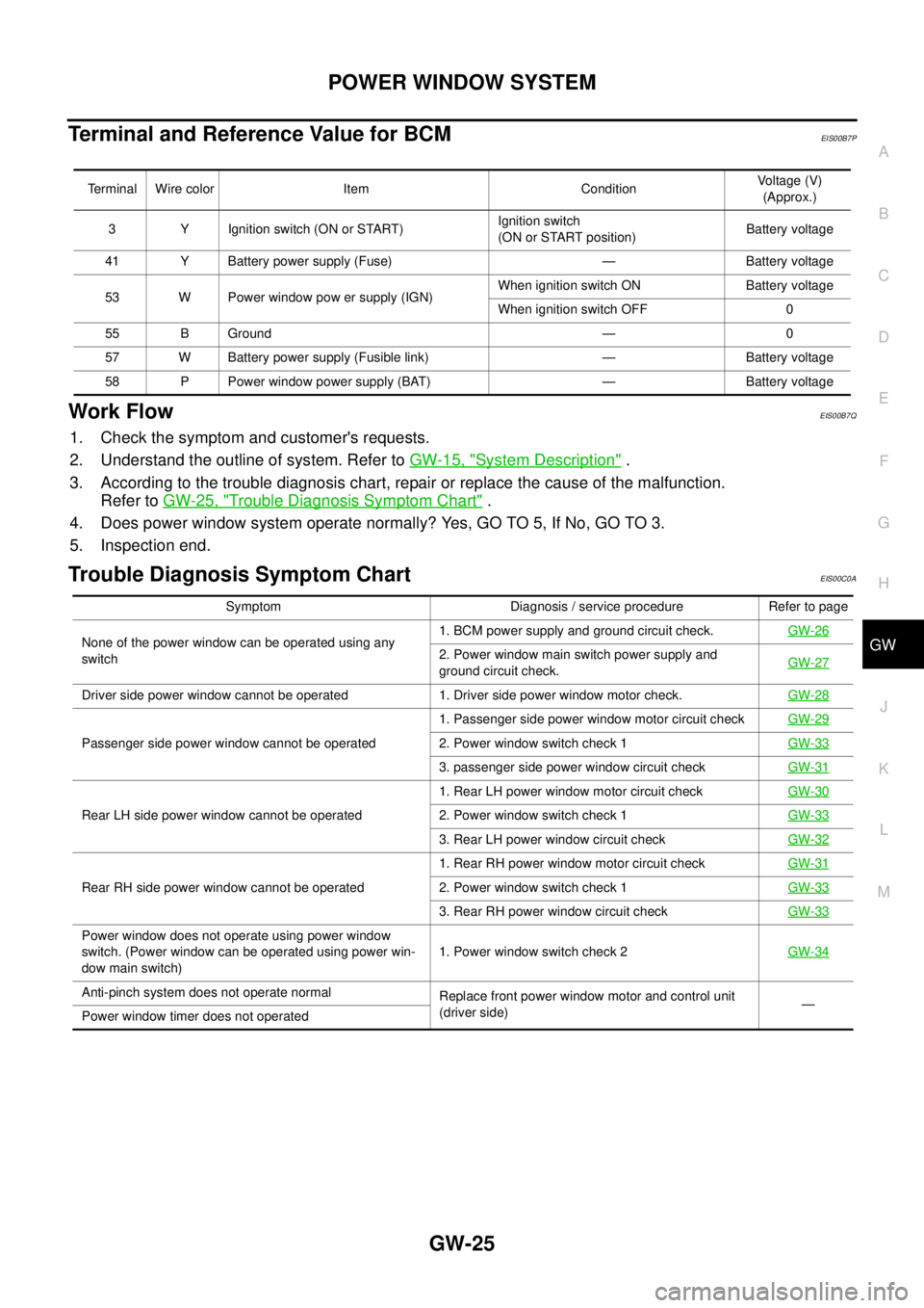
Terminal and Reference Value for BCMEIS00B7P
Work FlowEIS00B7Q
1. Check the symptom and customer's requests.
2. Understand the outline of system. Refer toGW-15, "
System Description".
3. According to the trouble diagnosis chart, repair or replace the cause of the malfunction.
Refer toGW-25, "
Trouble Diagnosis Symptom Chart".
4. Does power window system operate normally? Yes, GO TO 5, If No, GO TO 3.
5. Inspection end.
Trouble Diagnosis Symptom ChartEIS00C0A
Terminal Wire color Item ConditionVoltage (V)
(Approx.)
3 Y Ignition switch (ON or START)Ignition switch
(ON or START position)Battery voltage
41 Y Battery power supply (Fuse) — Battery voltage
53 W Power window pow er supply (IGN)When ignition switch ON Battery voltage
When ignition switch OFF 0
55 B Ground — 0
57 W Battery power supply (Fusible link) — Battery voltage
58 P Power window power supply (BAT) — Battery voltage
Symptom Diagnosis / service procedure Refer to page
None of the power window can be operated using any
switch1. BCM power supply and ground circuit check.GW-26
2. Power window main switch power supply and
ground circuit check.GW-27
Driver side power window cannot be operated 1. Driver side power window motor check.GW-28
Passenger side power window cannot be operated1. Passenger side power window motor circuit checkGW-292. Power window switch check 1GW-33
3. passenger side power window circuit checkGW-31
Rear LH side power window cannot be operated1. Rear LH power window motor circuit checkGW-302. Power window switch check 1GW-33
3. Rear LH power window circuit checkGW-32
Rear RH side power window cannot be operated1. Rear RH power window motor circuit checkGW-312. Power window switch check 1GW-33
3. Rear RH power window circuit checkGW-33
Power window does not operate using power window
switch. (Power window can be operated using power win-
dow main switch)1. Power window switch check 2GW-34
Anti-pinch system does not operate normal
Replace front power window motor and control unit
(driver side)—
Power window timer does not operated
Page 1714 of 3171
GW-28
POWER WINDOW SYSTEM
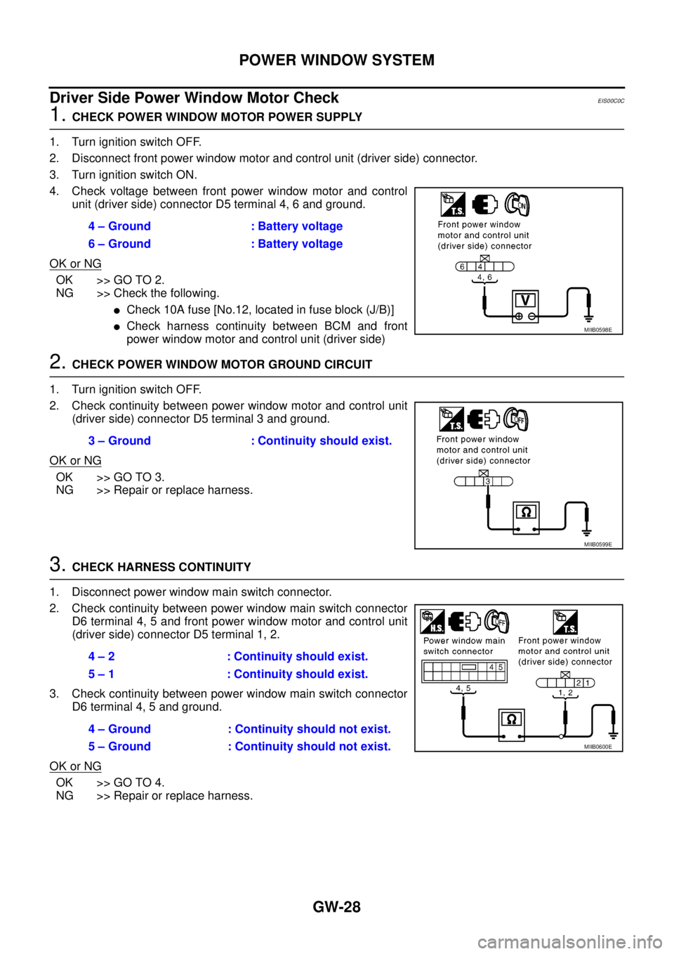
Driver Side Power Window Motor Check
EIS00C0C
1.CHECK POWER WINDOW MOTOR POWER SUPPLY
1. Turn ignition switch OFF.
2. Disconnect front power window motor and control unit (driver side) connector.
3. Turn ignition switch ON.
4. Check voltage between front power window motor and control
unit (driver side) connector D5 terminal 4, 6 and ground.
OK or NG
OK >> GO TO 2.
NG >> Check the following.
lCheck 10A fuse [No.12, located in fuse block (J/B)]
lCheck harness continuity between BCM and front
power window motor and control unit (driver side)
2.CHECK POWER WINDOW MOTOR GROUND CIRCUIT
1. Turn ignition switch OFF.
2. Check continuity between power window motor and control unit
(driver side) connector D5 terminal 3 and ground.
OK or NG
OK >> GO TO 3.
NG >> Repair or replace harness.
3.CHECK HARNESS CONTINUITY
1. Disconnect power window main switch connector.
2. Check continuity between power window main switch connector
D6 terminal 4, 5 and front power window motor and control unit
(driver side) connector D5 terminal 1, 2.
3. Check continuity between power window main switch connector
D6 terminal 4, 5 and ground.
OK or NG
OK >> GO TO 4.
NG >> Repair or replace harness.4 – Ground : Battery voltage
6 – Ground : Battery voltage
MIIB0598E
3 – Ground : Continuity should exist.
MIIB0599E
4 – 2 : Continuity should exist.
5 – 1 : Continuity should exist.
4 – Ground : Continuity should not exist.
5 – Ground : Continuity should not exist.
MIIB0600E
Page 1715 of 3171
POWER WINDOW SYSTEM
GW-29
C
D
E
F
G
H
J
K
L
MA
B
GW
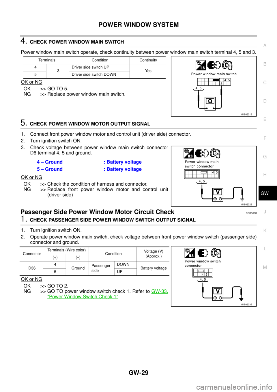
4.CHECK POWER WINDOW MAIN SWITCH
Power window main switch operate, check continuity between power window main switch terminal 4, 5 and 3.
OK or NG
OK >> GO TO 5.
NG >> Replace power window main switch.
5.CHECK POWER WINDOW MOTOR OUTPUT SIGNAL
1. Connect front power window motor and control unit (driver side) connector.
2. Turn ignition switch ON.
3. Check voltage between power window main switch connector
D6 terminal 4, 5 and ground.
OK or NG
OK >> Check the condition of harness and connector.
NG >> Replace front power window motor and control unit
(driver side)
Passenger Side Power Window Motor Circuit CheckEIS00C0D
1.CHECK PASSENGER SIDE POWER WINDOW SWITCH OUTPUT SIGNAL
1. Turn ignition switch ON.
2. Operate power window main switch, check voltage between front power window switch (passenger side)
connector and ground.
OK or NG
OK >> GO TO 2.
NG >> GO TO power window switch check 1. Refer toGW-33,
"Power Window Switch Check 1"
Terminals Condition Continuity
4
3Driver side switch UP
Ye s
5 DriversideswitchDOWN
MIIB0601E
4 – Ground : Battery voltage
5 – Ground : Battery voltage
MIIB0602E
ConnectorTerminals (Wire color)
ConditionVo l ta g e (V )
(Approx.)
(+) (–)
D364
GroundPassenger
sideDOWN
Battery voltage
5UP
MIIB0603E
Page 1740 of 3171
GW-54
REAR WINDOW DEFOGGER
CONSULT-II Function (BCM)
EIS00B8M
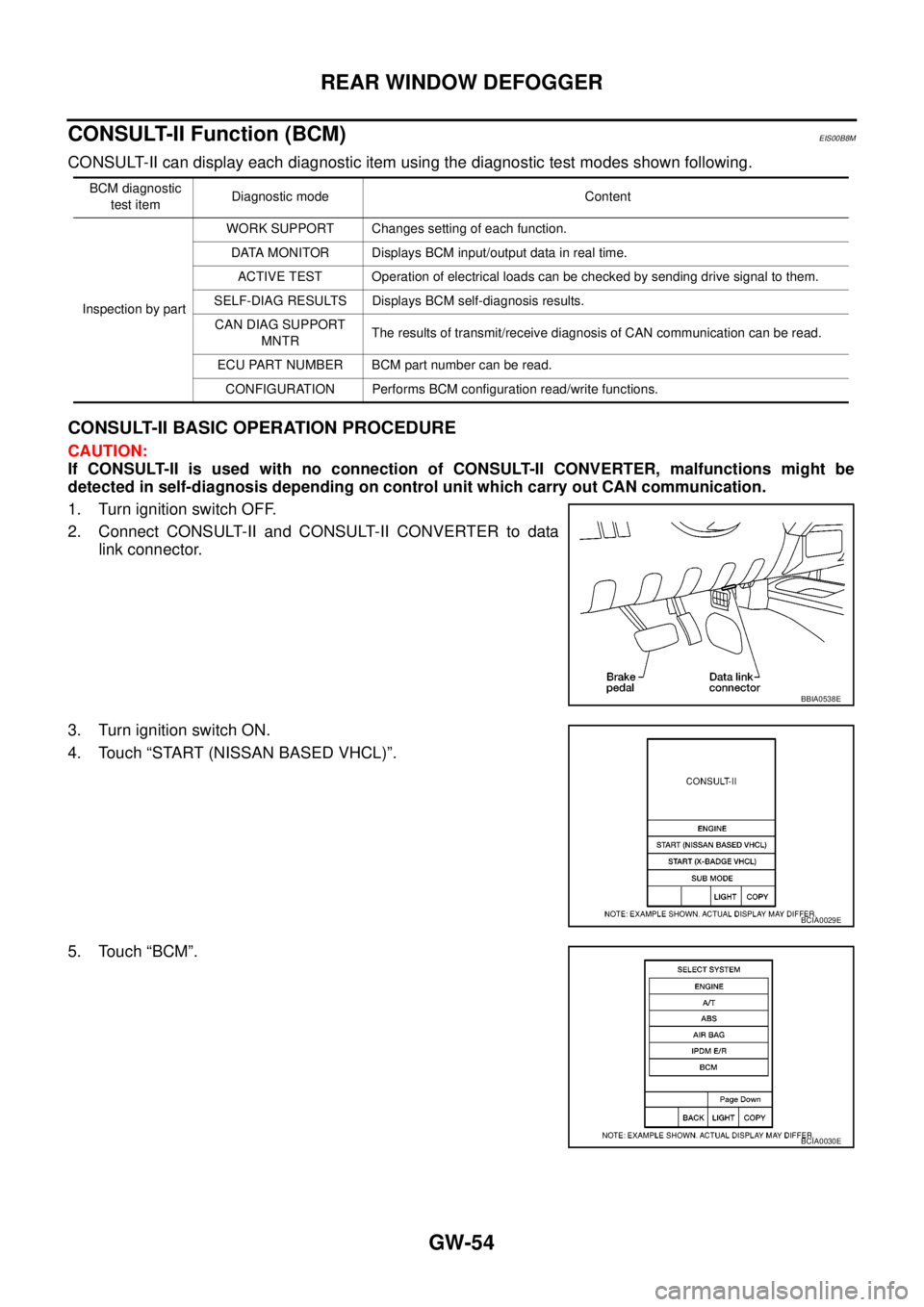
CONSULT-II can display each diagnostic item using the diagnostic test modes shown following.
CONSULT-II BASIC OPERATION PROCEDURE
CAUTION:
If CONSULT-II is used with no connection of CONSULT-II CONVERTER, malfunctions might be
detected in self-diagnosis depending on control unit which carry out CAN communication.
1. Turn ignition switch OFF.
2. Connect CONSULT-II and CONSULT-II CONVERTER to data
link connector.
3. Turn ignition switch ON.
4. Touch “START (NISSAN BASED VHCL)”.
5. Touch “BCM”.
BCM diagnostic
test itemDiagnostic mode Content
Inspection by partWORK SUPPORT Changes setting of each function.
DATA MONITOR Displays BCM input/output data in real time.
ACTIVE TEST Operation of electrical loads can be checked by sending drive signal to them.
SELF-DIAG RESULTS Displays BCM self-diagnosis results.
CAN DIAG SUPPORT
MNTRThe results of transmit/receive diagnosis of CAN communication can be read.
ECU PART NUMBER BCM part number can be read.
CONFIGURATION Performs BCM configuration read/write functions.
BBIA0538E
BCIA0029E
BCIA0030E
Page 1755 of 3171
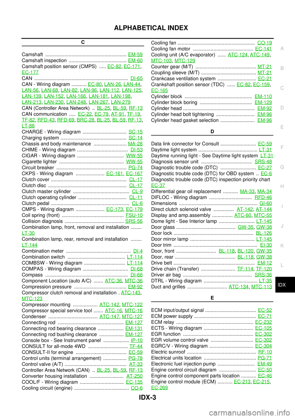
IDX-3
A
C
D
E
F
G
H
I
J
K
L B
IDX
ALPHABETICAL INDEX
C
Camshaft ...........................................................EM-59
Camshaft inspection ..........................................EM-60
Camshaft position sensor (CMPS) .....EC-82,EC-171,
EC-177
CAN ....................................................................DI-65
CAN - Wiring diagram ...........EC-80,LAN-26,LAN-44,
LAN-56
,LAN-68,LAN-82,LAN-96,LAN-112,LAN-125,
LAN-139
,LAN-152,LAN-166,LAN-181,LAN-198,
LAN-213
,LAN-230,LAN-248,LAN-267,LAN-279
CAN (Controller Area Network) ..BL-25,BL-59,RF-13
CAN communication .....EC-22,EC-79,AT-91,TF-19,
TF-82
,RFD-43,RFD-69,BRC-28,BL-25,BL-59,RF-13,
LT-88
CHARGE - Wiring diagram ................................SC-15
Charging system ................................................SC-14
Chassis and body maintenance ........................MA-28
CHIME - Wiring diagram .....................................DI-53
CIGAR - Wiring diagram ..................................WW-55
Cigarette lighter ...............................................WW-55
Circuit breaker ...................................................PG-74
CKPS - Wiring diagram .....................EC-161,EC-167
Clutch cover .......................................................CL-17
Clutch disc .........................................................CL-17
Clutch master cylinder .........................................CL-9
Clutch operating cylinder ...................................CL-11
Clutch pedal .........................................................CL-6
CMPS - Wiring diagram .....................EC-173,EC-179
Coil spring (front) .............................................FSU-10
Collision diagnosis ...........................................SRS-56
Combination lamp, front, removal and installation ........
LT-30
Combination lamp, rear, removal and installation ........
LT-144
Combination meter ...............................................DI-4
Combination switch ..........................................LT-114
COMBSW - Wiring diagram ..............................LT-114
COMPAS - Wiring diagram .................................DI-68
Compass ............................................................DI-66
Component Location (auto A/C) .......ATC-36,MTC-36
Compression pressure ......................................EM-92
Compressor clutch removal and installation .ATC-143,
MTC-123
Compressor mounting ..................ATC-142,MTC-122
Compressor special service tool .......ATC-16,MTC-16
Condenser ....................................ATC-147,MTC-127
Connecting rod ................................................EM-127
Connecting rod bearing clearance ...................EM-131
Connecting rod bushing clearance ..................EM-127
Console box - See Instrument panel ...................IP-10
CONSULT for all-mode 4WD .............................TF-44
CONSULT-II for engine .....................................EC-59
Control units (terminal arrangement) .................PG-78
Control valve (A/T) .............................................AT-33
Controller Area Network (CAN) ..BL-25,BL-59,RF-13
Converter housing installation .........................AT-250
COOL/F - Wiring diagram ................................EC-135
Cooling circuit (engine) ........................................CO-6
Cooling fan ........................................................CO-19
Cooling fan motor ............................................EC-141
Cooling unit (A/C evaporator) ......ATC-124,ATC-149,
MTC-103
,MTC-129
Counter gear (M/T) ............................................MT-21
Coupling sleeve (M/T) ........................................MT-21
Crankcase ventilation system ............................EC-21
Crankshaft position sensor (TDC) ......EC-82,EC-159,
EC-165
Cylinder block .................................................EM-110
Cylinder block boring ......................................EM-129
Cylinder head ....................................................EM-92
Cylinder head bolt tightening ............................EM-96
Cylinder head gasket selection .........................EM-96
D
Data link connector for Consult ..........................EC-59
Daytime light system ...........................................LT-31
Daytime running light - See Daytime light systemLT-31
Diagnosis sensor unit .....................................SRS-48
Diagnostic trouble code (DTC) ..........................EC-27
Diagnostic trouble code (DTC) for OBD system ..EC-6
Diagnostic trouble code (DTC) inspection priority chart
EC-37
Differential gear oil replacement ...........MA-33,MA-34
DIFLOC - Wiring diagram ...............................RFD-46
Dimensions .........................................................GI-60
Direct clutch solenoid valve ...............AT-142,AT-144
Display and amp.assembly ...............ATC-60,MTC-55
Dome light - See Interior lamp ..........................LT-145
Door glass ...........................................GW-35,GW-38
Door lock ..........................................................BL-126
Door mirror lamp ...............................................LT-145
Door trim .............................................................EI-30
Door, front .............................BL-118,BL-120,GW-35
Door, rear ............................................BL-118,GW-38
Drive belt ...........................................................EM-12
Drive chain (Transfer) .........................TF-114,TF-120
Driver air bag ..................................................SRS-36
DTRL - Wiring diagram .......................................LT-35
Duct and grilles .............................ATC-134,MTC-113
E
ECM input/output signal .....................................EC-52
ECM power supply .............................................EC-71
ECM relay ........................................................EC-232
ECTS - Wiring diagram ....................................EC-105
EGR function ...................................................EC-302
EGR volume control valve ...............................EC-302
EGRC/V - Wiring diagram ................................EC-304
Electric sunroof ..................................................RF-10
Electrical units location ......................................PG-71
Electronic fuel injection pump ...........................EM-49
Engine control circuit diagram ...........................EC-50
Engine control component parts location ...........EC-46
Engine control module (ECM) ...........EC-213,EC-215,
EC-269
Page 1756 of 3171
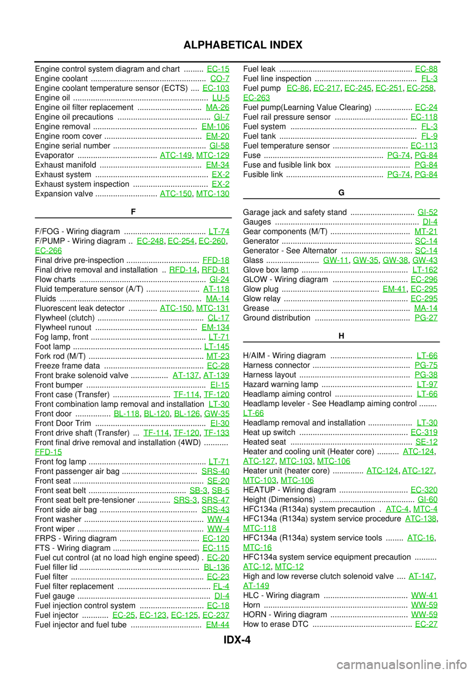
IDX-4
ALPHABETICAL INDEX
Engine control system diagram and chart .........EC-15
Engine coolant ....................................................CO-7
Engine coolant temperature sensor (ECTS) ....EC-103
Engine oil .............................................................LU-5
Engine oil filter replacement .............................MA-26
Engine oil precautions ..........................................GI-7
Engine removal ...............................................EM-106
Engine room cover ............................................EM-20
Engine serial number ..........................................GI-58
Evaporator ....................................ATC-149,MTC-129
Exhaust manifold ..............................................EM-34
Exhaust system ...................................................EX-2
Exhaust system inspection ..................................EX-2
Expansion valve ............................ATC-150,MTC-130
F
F/FOG - Wiring diagram .....................................LT-74
F/PUMP - Wiring diagram ..EC-248,EC-254,EC-260,
EC-266
Final drive pre-inspection .................................FFD-18
Final drive removal and installation ..RFD-14,RFD-81
Flow charts .........................................................GI-24
Fluid temperature sensor (A/T) ........................AT-118
Fluids ................................................................MA-14
Fluorescent leak detector .............ATC-150,MTC-131
Flywheel (clutch) ................................................CL-17
Flywheel runout ..............................................EM-134
Fog lamp, front ....................................................LT-71
Foot lamp ..........................................................LT-145
Fork rod (M/T) ....................................................MT-23
Freeze frame data .............................................EC-28
Front brake solenoid valve .................AT-137,AT-139
Front bumper ......................................................EI-15
Front case (Transfer) ..........................TF-114,TF-120
Front combination lamp removal and installationLT-30
Front door ................BL-118,BL-120,BL-126,GW-35
Front Door Trim ..................................................EI-30
Front drive shaft (Transfer) ...TF-114,TF-120,TF-133
Front final drive removal and installation (4WD) ...........
FFD-15
Front fog lamp .....................................................LT-71
Front passenger air bag ..................................SRS-40
Front seat ...........................................................SE-20
Front seat belt ............................................SB-3,SB-5
Front seat belt pre-tensioner ...............SRS-3,SRS-47
Front side air bag ............................................SRS-43
Front washer ......................................................WW-4
Front wiper .........................................................WW-4
FRPS - Wiring diagram ....................................EC-120
FTS - Wiring diagram .......................................EC-115
Fuel cut control (at no load high engine speed) .EC-20
Fuel filler lid ......................................................BL-136
Fuel filter ............................................................EC-23
Fuel filter replacement ..........................................FL-4
Fuel gauge ............................................................DI-4
Fuel injection control system .............................EC-18
Fuel injector ............EC-25,EC-123,EC-125,EC-237
Fuel injector and fuel tube ................................EM-44
Fuel leak ............................................................EC-88
Fuel line inspection ..............................................FL-3
Fuel pumpEC-86,EC-217,EC-245,EC-251,EC-258,
EC-263
Fuel pump(Learning Value Clearing) .................EC-24
Fuel rail pressure sensor .................................EC-118
Fuel system .........................................................FL-3
Fuel tank ..............................................................FL-9
Fuel temperature sensor ..................................EC-113
Fuse ......................................................PG-74,PG-84
Fuse and fusible link box ..................................PG-84
Fusible link ............................................PG-74,PG-84
G
Garage jack and safety stand .............................GI-52
Gauges .................................................................DI-4
Gear components (M/T) ....................................MT-21
Generator ...........................................................SC-14
Generator - See Alternator ................................SC-14
Glass ........................GW-11,GW-35,GW-38,GW-43
Glove box lamp ................................................LT-162
GLOW - Wiring diagram ..................................EC-296
Glow plug ............................................EM-41,EC-295
Glow relay ........................................................EC-295
Grease ..............................................................MA-14
Ground distribution ...........................................PG-27
H
H/AIM - Wiring diagram .....................................LT-66
Harness connector ............................................PG-75
Harness layout ..................................................PG-38
Hazard warning lamp .........................................LT-97
Headlamp aiming control ...................................LT-66
Headlamp leveler - See Headlamp aiming control ........
LT-66
Headlamp removal and installation ....................LT-30
Heat up switch .................................................EC-319
Heated seat .......................................................SE-12
Heater and cooling unit (Heater core) ..........ATC-124,
ATC-127
,MTC-103,MTC-106
Heater unit (heater core) ..............ATC-124,ATC-127,
MTC-103
,MTC-106
HEATUP - Wiring diagram ...............................EC-320
Height (Dimensions) ...........................................GI-60
HFC134a (R134a) system precaution .ATC-4,MTC-4
HFC134a (R134a) system service procedureATC-138,
MTC-118
HFC134a (R134a) system service tools ........ATC-16,
MTC-16
HFC134a system service equipment precaution ..........
ATC-12
,MTC-12
High and low reverse clutch solenoid valve ....AT-147,
AT-149
HLC - Wiring diagram ......................................WW-41
Horn .................................................................WW-59
HORN - Wiring diagram ...................................WW-59
How to erase DTC .............................................EC-27
Page 1757 of 3171
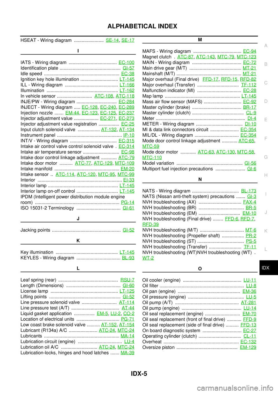
IDX-5
A
C
D
E
F
G
H
I
J
K
L B
IDX
ALPHABETICAL INDEX
HSEAT - Wiring diagram .......................SE-14,SE-17
I
IATS - Wiring diagram .....................................EC-100
Identification plate ...............................................GI-57
Idle speed ..........................................................EC-38
Ignition key hole illumination .............................LT-145
ILL - Wiring diagram .........................................LT-166
Illumination .......................................................LT-162
In vehicle sensor ...........................ATC-108,ATC-118
INJE/PW - Wiring diagram ...............................EC-284
INJECT - Wiring diagram .....EC-128,EC-240,EC-289
Injection nozzle .......EM-44,EC-123,EC-125,EC-237
Injector adjustment value ...................EC-271,EC-273
Injector adjustment value registration ................EC-25
Input clutch solenoid valve .................AT-132,AT-134
Instrument panel ..................................................IP-10
INT/V - Wiring diagram ....................................EC-315
Intake air control valve control solenoid valve .EC-314
Intake air temperature sensor ............................EC-98
Intake door control linkage adjustment ............ATC-79
Intake door motor ..........ATC-77,ATC-129,MTC-109
Intake manifold ..................................................EM-20
Intake sensor ..ATC-114,ATC-120,MTC-95,MTC-99
Interior .................................................................EI-33
Interior lamp ......................................................LT-145
Interior lamp on-off control ................................LT-145
IPDM (Intelligent power distribution module engine
room) .................................................................PG-14
ISO 15031-2 Terminology ..................................GI-61
J
Jacking points .....................................................GI-52
K
Key illumination ................................................LT-145
KEYLES - Wiring diagram ..................................BL-93
L
Leaf spring (rear) ..............................................RSU-7
Length (Dimensions) ..........................................GI-60
License lamp ....................................................LT-125
Lifting points .......................................................GI-52
Line pressure solenoid valve ...........................AT-114
Line pressure test (A/T) .....................................AT-44
Liquid gasket application ................EM-5,LU-2,CO-2
Location of electrical units .................................PG-71
Low coast brake solenoid valve ..........AT-152,AT-154
Lubricant (R134a) A/C ......................ATC-24,MTC-24
Lubricants ..........................................................MA-14
Lubrication circuit (engine) ..................................LU-4
Lubrication oil A/C ............................ATC-24,MTC-24
Lubrication-locks, hinges and hood latches .......MA-39
M
MAFS - Wiring diagram .....................................EC-94
Magnet clutch .ATC-87,ATC-143,MTC-79,MTC-123
MAIN - Wiring diagram ......................................EC-72
Main drive gear (M/T) ........................................MT-21
Mainshaft (M/T) ..................................................MT-21
Major overhaul (Final drive)FFD-17,RFD-15,RFD-82
Major overhaul (Transfer) ................................TF-112
Malfunction indicator (MI) ..................................EC-28
Map lamp ..........................................................LT-145
Mass air flow sensor (MAFS) .............................EC-92
Master cylinder (brake) ......................................BR-17
Master cylinder (clutch) ........................................CL-9
Meter .....................................................................DI-4
METER - Wiring diagram ....................................DI-10
MI & data link connectors circuit ......................EC-354
MIL/DL - Wiring diagram ..................................EC-354
Mode door control linkage adjustment ............ATC-65,
MTC-59
Mode door motor ............ATC-63,ATC-130,MTC-58,
MTC-110
Model variation ...................................................GI-56
Multiport fuel injection precautions .......................GI-6
N
NATS - Wiring diagram ....................................BL-173
NATS (Nissan anti-theft system) precautions .......GI-3
NVH troubleshooting (AX) .................................FAX-4
NVH troubleshooting (BR) ...................................BR-5
NVH troubleshooting (EM) ................................EM-10
NVH troubleshooting (Final drive) ........FFD-6,RFD-7,
RFD-39
NVH troubleshooting (M/T) ..................................MT-6
NVH troubleshooting (Propeller shaft) .................PR-2
NVH troubleshooting (ST) ....................................PS-5
NVH troubleshooting (Transfer) .........................TF-11
NVH troubleshooting (WT)NVH troubleshooting (WT) .
WT-2
O
Oil cooler (engine) .............................................LU-11
Oil filter .................................................................LU-8
Oil pan (engine) ................................................EM-36
Oil pressure (engine) ...........................................LU-5
Oil pump (A/T) .................................................AT-281
Oil pump (engine) ..............................................LU-14
Oil seal replacement (engine) ...........................EM-70
Oil seal replacement (front of final drive) ...........FFD-9
Oil seal replacement (side of final drive) ..........FFD-13
On board diagnostic system ..............................EC-27
Operating cylinder (clutch) .................................CL-11
Overheat ..........................................................EC-132
Oversize piston ...............................................EM-129
Page 1759 of 3171
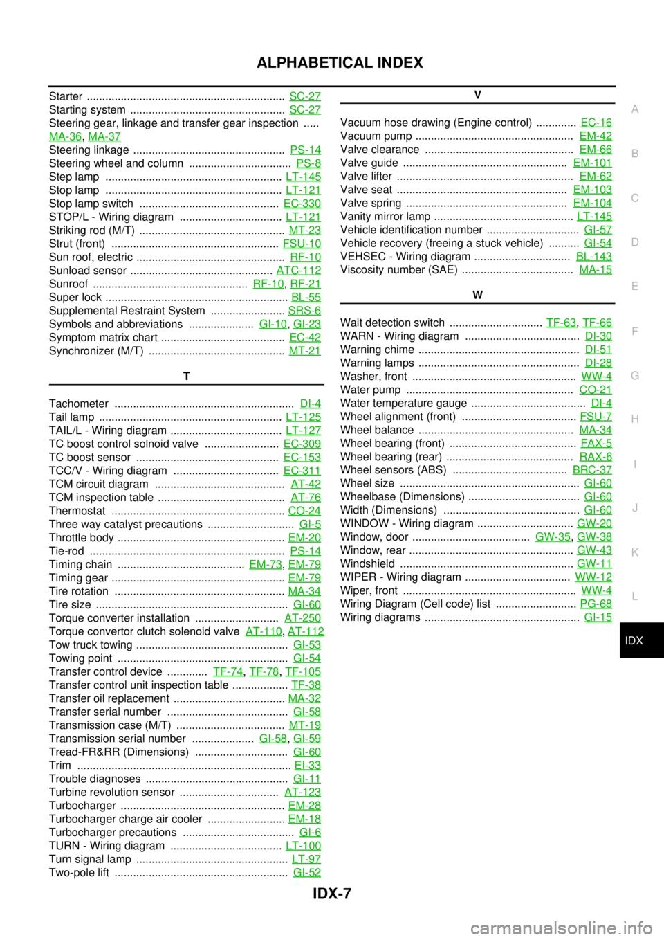
IDX-7
A
C
D
E
F
G
H
I
J
K
L B
IDX
ALPHABETICAL INDEX
Starter ................................................................SC-27
Starting system ..................................................SC-27
Steering gear, linkage and transfer gear inspection .....
MA-36
,MA-37
Steering linkage .................................................PS-14
Steering wheel and column .................................PS-8
Step lamp .........................................................LT-145
Stop lamp .........................................................LT-121
Stop lamp switch .............................................EC-330
STOP/L - Wiring diagram .................................LT-121
Striking rod (M/T) ...............................................MT-23
Strut (front) ......................................................FSU-10
Sun roof, electric ................................................RF-10
Sunload sensor ..............................................ATC-112
Sunroof ..................................................RF-10,RF-21
Super lock ...........................................................BL-55
Supplemental Restraint System ........................SRS-6
Symbols and abbreviations .....................GI-10,GI-23
Symptom matrix chart ........................................EC-42
Synchronizer (M/T) ............................................MT-21
T
Tachometer ..........................................................DI-4
Tail lamp ...........................................................LT-125
TAIL/L - Wiring diagram ....................................LT-127
TC boost control solnoid valve ........................EC-309
TC boost sensor ..............................................EC-153
TCC/V - Wiring diagram ..................................EC-311
TCM circuit diagram ..........................................AT-42
TCM inspection table .........................................AT-76
Thermostat ........................................................CO-24
Three way catalyst precautions ............................GI-5
Throttle body ......................................................EM-20
Tie-rod ...............................................................PS-14
Timing chain .........................................EM-73,EM-79
Timing gear ........................................................EM-79
Tire rotation .......................................................MA-34
Tire size ..............................................................GI-60
Torque converter installation ...........................AT-250
Torque convertor clutch solenoid valveAT-110,AT-112
Tow truck towing .................................................GI-53
Towing point .......................................................GI-54
Transfer control device .............TF-74,TF-78,TF-105
Transfer control unit inspection table ..................TF-38
Transfer oil replacement ....................................MA-32
Transfer serial number .......................................GI-58
Transmission case (M/T) ...................................MT-19
Transmission serial number ....................GI-58,GI-59
Tread-FR&RR (Dimensions) ..............................GI-60
Trim .....................................................................EI-33
Trouble diagnoses ..............................................GI-11
Turbine revolution sensor ................................AT-123
Turbocharger .....................................................EM-28
Turbocharger charge air cooler .........................EM-18
Turbocharger precautions ....................................GI-6
TURN - Wiring diagram ....................................LT-100
Turn signal lamp .................................................LT-97
Two-pole lift ........................................................GI-52
V
Vacuum hose drawing (Engine control) .............EC-16
Vacuum pump ...................................................EM-42
Valve clearance ................................................EM-66
Valve guide .....................................................EM-101
Valve lifter .........................................................EM-62
Valve seat .......................................................EM-103
Valve spring ....................................................EM-104
Vanity mirror lamp .............................................LT-145
Vehicle identification number ..............................GI-57
Vehicle recovery (freeing a stuck vehicle) ..........GI-54
VEHSEC - Wiring diagram ...............................BL-143
Viscosity number (SAE) ....................................MA-15
W
Wait detection switch ..............................TF-63
,TF-66
WARN - Wiring diagram .....................................DI-30
Warning chime ....................................................DI-51
Warning lamps ....................................................DI-28
Washer, front .....................................................WW-4
Water pump ......................................................CO-21
Water temperature gauge .....................................DI-4
Wheel alignment (front) .....................................FSU-7
Wheel balance ..................................................MA-34
Wheel bearing (front) .........................................FAX-5
Wheel bearing (rear) .........................................RAX-6
Wheel sensors (ABS) .....................................BRC-37
Wheel size ..........................................................GI-60
Wheelbase (Dimensions) ....................................GI-60
Width (Dimensions) ............................................GI-60
WINDOW - Wiring diagram ...............................GW-20
Window, door ......................................GW-35,GW-38
Window, rear .....................................................GW-43
Windshield ........................................................GW-11
WIPER - Wiring diagram ..................................WW-12
Wiper, front ........................................................WW-4
Wiring Diagram (Cell code) list ..........................PG-68
Wiring diagrams ..................................................GI-15