2005 NISSAN NAVARA control unit
[x] Cancel search: control unitPage 32 of 3171
AT-24
A/T CONTROL SYSTEM
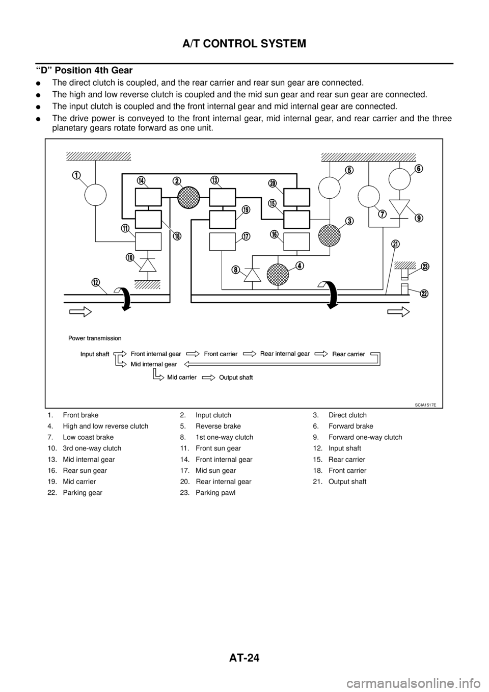
“D” Position 4th Gear
lThe direct clutch is coupled, and the rear carrier and rear sun gear are connected.
lThe high and low reverse clutch is coupled and the mid sun gear and rear sun gear are connected.
lThe input clutch is coupled and the front internal gear and mid internal gear are connected.
lThe drive power is conveyed to the front internal gear, mid internal gear, and rear carrier and the three
planetary gears rotate forward as one unit.
1. Front brake 2. Input clutch 3. Direct clutch
4. High and low reverse clutch 5. Reverse brake 6. Forward brake
7. Low coast brake 8. 1st one-way clutch 9. Forward one-way clutch
10. 3rd one-way clutch 11. Front sun gear 12. Input shaft
13. Mid internal gear 14. Front internal gear 15. Rear carrier
16. Rear sun gear 17. Mid sun gear 18. Front carrier
19. Mid carrier 20. Rear internal gear 21. Output shaft
22. Parking gear 23. Parking pawl
SCIA1517E
Page 36 of 3171

AT-28
A/T CONTROL SYSTEM
CAN Communication
ECS00FWJ
SYSTEM DESCRIPTION
CAN (Controller Area Network) is a serial communication line for real time application. It is an on-vehicle mul-
tiplex communication line with high data communication speed and excellent error detection ability. Many elec-
tronic control units are equipped onto a vehicle, and each control unit shares information and links with other
control units during operation (not independent). In CAN communication, control units are connected with 2
communication lines (CAN H line, CAN L line) allowing a high rate of information transmission with less wiring.
Each control unit transmits/receives data but selectively reads required data only. For details, refer toLAN-30,
"CAN Communication Unit".
Input/Output Signal of TCMECS00FWK
*1: Spare for vehicle speed sensor·A/T (revolution sensor)
*2: Spare for accelerator pedal position signal
*3: If these input and output signals are different, the TCM triggers the fail-safe function.
*4: Used as a condition for starting self-diagnosis; if self-diagnosis are not started, it is judged that there is some kind of error.
*5: Input by CAN communications.
*6: Output by CAN communications.Control itemLine
pressure
controlVehicle
speed
controlShift
controlLock-up
controlEngine
brake
controlFail-safe
function
(*3)Self-diag-
nostics
function
InputAccelerator pedal position signal
(*5)XXXXXX X
Vehicle speed sensor A/T
(revolution sensor)XXXXXX X
Vehicle speed sensor MTR
(*1) (*5)X
Closed throttle position signal
(*5)X(*2) X X X X(*4)
Wide open throttle position signal
(*5)XX(*4)
Turbine revolution sensor 1 X X X X X
Turbine revolution sensor 2
(for 4th speed only)XXXXX
Engine speed signals
(*5)XXXXXX X
Stop lamp switch signal
(*5)XXX X(*4)
A/T fluid temperature sensors 1, 2 X X X X X X
ASCDOperation signal
(*5)XXX
Overdrive cancel signal
(*5)X
OutputDirect clutch solenoid
(ATF pressure switch 5)XX X X
Input clutch solenoid
(ATF pressure switch 3)XX X X
High and low reverse clutch solenoid
(ATF pressure switch 6)XX X X
Front brake solenoid
(ATF pressure switch 1)XX X X
Low coast brake solenoid
(ATF pressure switch 2)XX XX X
Line pressure solenoid X X X X X X X
TCC solenoid X X X
Self-diagnosis table
(*6)X
Starter relayXX
Page 87 of 3171
TROUBLE DIAGNOSIS
AT-79
D
E
F
G
H
I
J
K
L
MA
B
AT
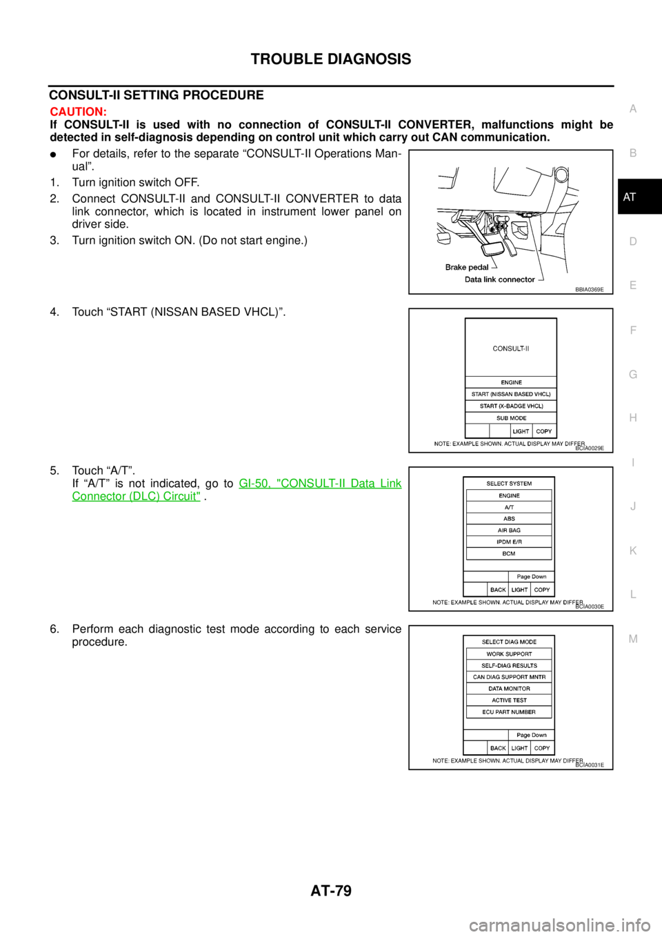
CONSULT-II SETTING PROCEDURE
CAUTION:
If CONSULT-II is used with no connection of CONSULT-II CONVERTER, malfunctions might be
detected in self-diagnosis depending on control unit which carry out CAN communication.
lFor details, refer to the separate “CONSULT-II Operations Man-
ual”.
1. Turn ignition switch OFF.
2. Connect CONSULT-II and CONSULT-II CONVERTER to data
link connector, which is located in instrument lower panel on
driver side.
3. Turn ignition switch ON. (Do not start engine.)
4. Touch “START (NISSAN BASED VHCL)”.
5. Touch “A/T”.
If “A/T” is not indicated, go toGI-50, "
CONSULT-II Data Link
Connector (DLC) Circuit".
6. Perform each diagnostic test mode according to each service
procedure.
BBIA0369E
BCIA0029E
BCIA0030E
BCIA0031E
Page 92 of 3171
AT-84
TROUBLE DIAGNOSIS
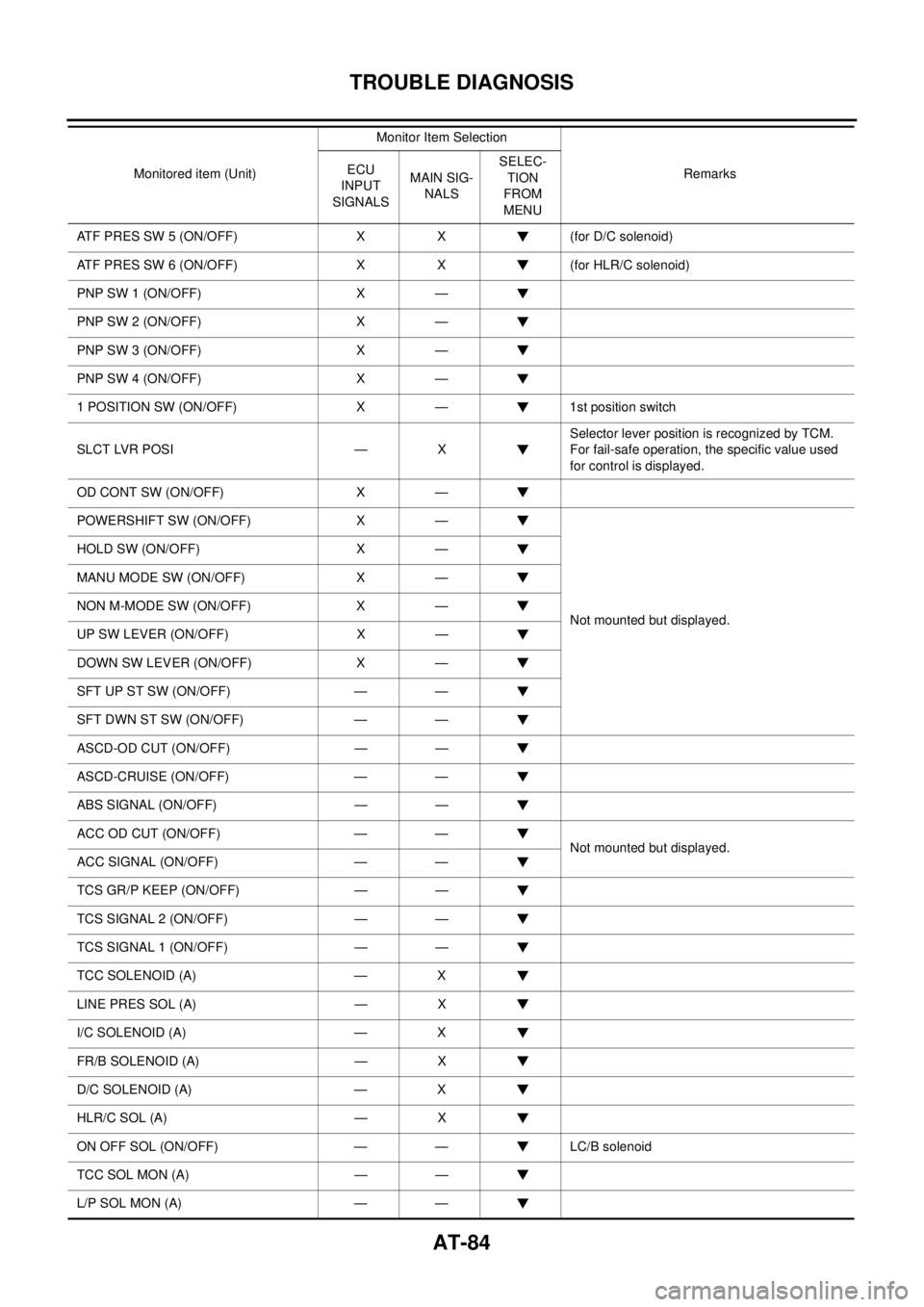
ATF PRES SW 5 (ON/OFF) X X (for D/C solenoid)
ATF PRES SW 6 (ON/OFF) X X (for HLR/C solenoid)
PNP SW 1 (ON/OFF) X —
PNP SW 2 (ON/OFF) X —
PNP SW 3 (ON/OFF) X —
PNP SW 4 (ON/OFF) X —
1 POSITION SW (ON/OFF) X — 1st position switch
SLCT LVR POSI — XSelector lever position is recognized by TCM.
For fail-safe operation, the specific value used
for control is displayed.
OD CONT SW (ON/OFF) X —
POWERSHIFT SW (ON/OFF) X —
Not mounted but displayed. HOLD SW (ON/OFF) X —
MANU MODE SW (ON/OFF) X —
NON M-MODE SW (ON/OFF) X —
UP SW LEVER (ON/OFF) X —
DOWN SW LEVER (ON/OFF) X —
SFTUPSTSW(ON/OFF) — —
SFT DWN ST SW (ON/OFF) — —
ASCD-OD CUT (ON/OFF) — —
ASCD-CRUISE (ON/OFF) — —
ABS SIGNAL (ON/OFF) — —
ACC OD CUT (ON/OFF) — —
Not mounted but displayed.
ACC SIGNAL (ON/OFF) — —
TCS GR/P KEEP (ON/OFF) — —
TCS SIGNAL 2 (ON/OFF) — —
TCS SIGNAL 1 (ON/OFF) — —
TCC SOLENOID (A) — X
LINE PRES SOL (A) — X
I/C SOLENOID (A) — X
FR/B SOLENOID (A) — X
D/C SOLENOID (A) — X
HLR/C SOL (A) — X
ON OFF SOL (ON/OFF) — — LC/B solenoid
TCC SOL MON (A) — —
L/P SOL MON (A) — —Monitored item (Unit)Monitor Item Selection
Remarks ECU
INPUT
SIGNALSMAIN SIG-
NALSSELEC-
TION
FROM
MENU
Page 98 of 3171
AT-90
TROUBLE DIAGNOSIS
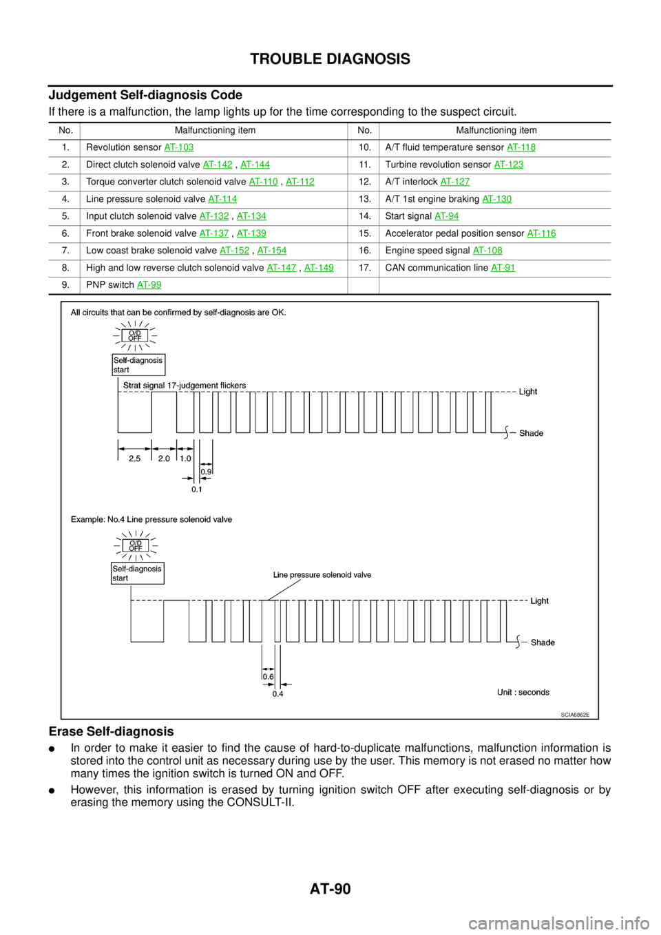
Judgement Self-diagnosis Code
If there is a malfunction, the lamp lights up for the time corresponding to the suspect circuit.
Erase Self-diagnosis
lIn order to make it easier to find the cause of hard-to-duplicate malfunctions, malfunction information is
stored into the control unit as necessary during use by the user. This memory is not erased no matter how
many times the ignition switch is turned ON and OFF.
lHowever, this information is erased by turning ignition switch OFF after executing self-diagnosis or by
erasing the memory using the CONSULT-II.
No. Malfunctioning item No. Malfunctioning item
1. Revolution sensorAT- 1 0 3
10. A/T fluid temperature sensorAT- 11 8
2. Direct clutch solenoid valveAT- 1 4 2,AT-14411. Turbine revolution sensorAT- 1 2 3
3. Torque converter clutch solenoid valveAT- 11 0,AT- 11 212. A/T interlockAT-127
4. Line pressure solenoid valveAT- 11 413. A/T 1st engine brakingAT-130
5. Input clutch solenoid valveAT- 1 3 2,AT- 1 3 414. Start signalAT- 9 4
6. Front brake solenoid valveAT-137,AT- 1 3 915. Accelerator pedal position sensorAT- 11 6
7. Low coast brake solenoid valveAT- 1 5 2,AT- 1 5 416. Engine speed signalAT-108
8. High and low reverse clutch solenoid valveAT-147,AT- 1 4 917. CAN communication lineAT- 9 1
9. PNP switchAT- 9 9
SCIA6862E
Page 99 of 3171
DTC U1000 CAN COMMUNICATION LINE
AT-91
D
E
F
G
H
I
J
K
L
MA
B
AT
DTC U1000 CAN COMMUNICATION LINEPFP:23710
DescriptionECS00FXC
CAN (Controller Area Network) is a serial communication line for real time application. It is an on-vehicle mul-
tiplex communication line with high data communication speed and excellent malfunction detection ability.
Many electronic control units are equipped onto a vehicle, and each control unit shares information and links
with other control units during operation (not independent). In CAN communication, control units are con-
nected with 2 communication lines (CAN H line, CAN L line) allowing a high rate of information transmission
with less wiring. Each control unit transmits/receives data but selectively reads required data only.
On Board Diagnosis LogicECS00FXD
Diagnostic trouble code “U1000 CAN COMM CIRCUIT” with CONSULT-II or 17th judgement flicker without
CONSULT-II is detected when TCM cannot communicate to other control units.
Possible CauseECS00FXE
Harness or connectors
(CAN communication line is open or shorted.)
DTC Confirmation ProcedureECS00FXF
NOTE:
If “DTC Confirmation Procedure” has been previously performed, always turn ignition switch OFF and
wait at least 10 seconds before performing the next test.
After the repair, perform the following procedure to confirm the malfunction is eliminated.
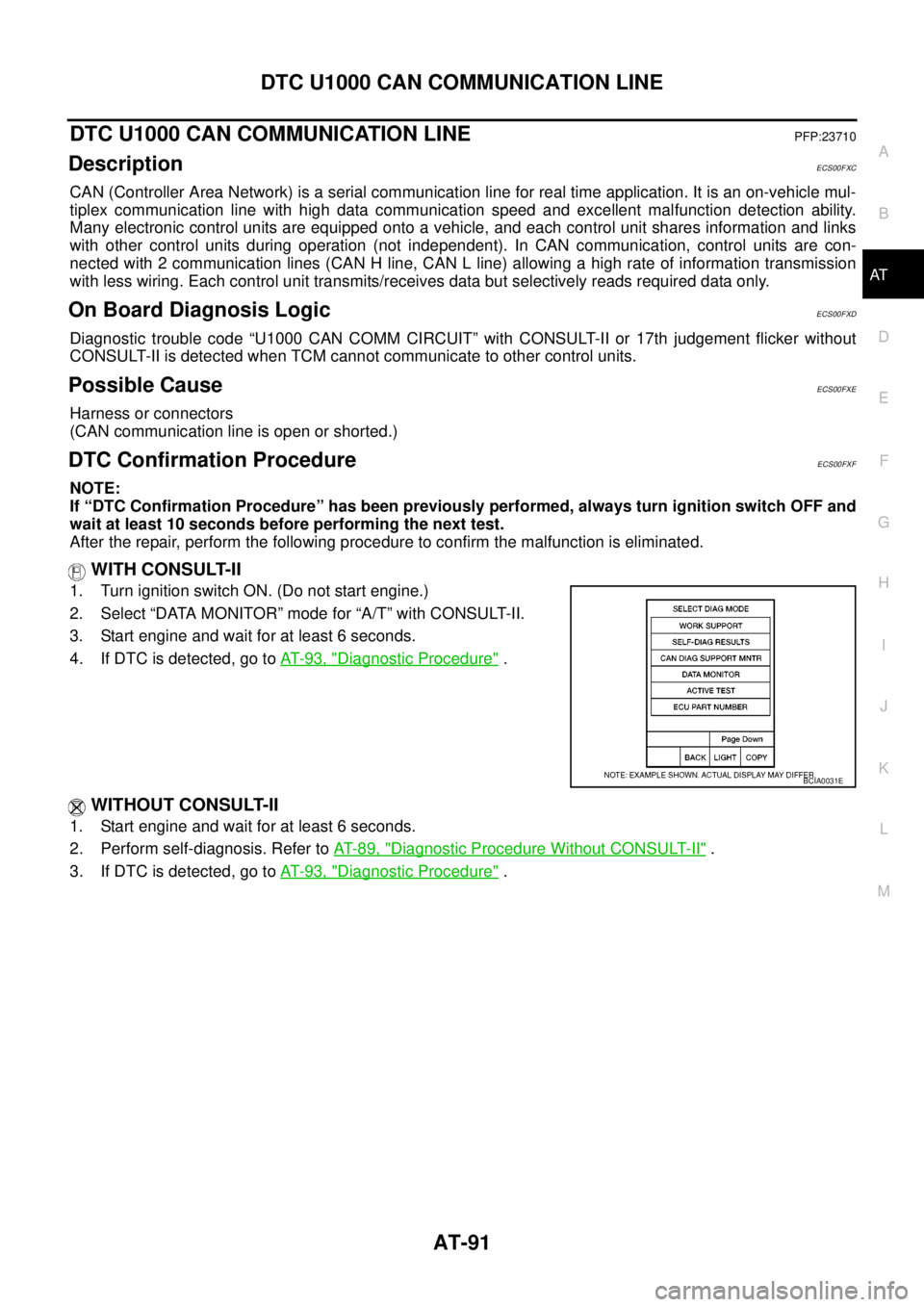
WITH CONSULT-II
1. Turn ignition switch ON. (Do not start engine.)
2. Select “DATA MONITOR” mode for “A/T” with CONSULT-II.
3. Start engine and wait for at least 6 seconds.
4. If DTC is detected, go toAT-93, "
Diagnostic Procedure".
WITHOUT CONSULT-II
1. Start engine and wait for at least 6 seconds.
2. Perform self-diagnosis. Refer toAT-89, "
Diagnostic Procedure Without CONSULT-II".
3. If DTC is detected, go toAT-93, "
Diagnostic Procedure".
BCIA0031E
Page 336 of 3171

ATC-2
DATA MONITOR .................................................. 34
How to Perform Trouble Diagnosis for Quick and
Accurate Repair ...................................................... 35
WORK FLOW ...................................................... 35
SYMPTOM TABLE .............................................. 35
Component Parts and Harness Connector Location... 36
ENGINE COMPARTMENT .................................. 36
FRONT PASSENGER COMPARTMENT ............ 37
Schematic —LHD MODELS— ............................... 38
Wiring Diagram —A/C— —LHD MODELS— ......... 39
Schematic —RHD MODELS— ............................... 46
Wiring Diadram —A/C— —RHD MODELS— ......... 47
Front Air Control Terminals and Reference Value... 53
PIN CONNECTOR TERMINAL LAYOUT ............ 53
TERMINALS AND REFERENCE VALUE FOR
FRONT AIR CONTROL ....................................... 53
A/C System Self-diagnosis Function ...................... 55
DESCRIPTION .................................................... 55
Operational Check .................................................. 57
CHECKING MEMORY FUNCTION ..................... 57
CHECKING BLOWER ......................................... 57
CHECKING DISCHARGE AIR ............................ 58
CHECKING RECIRCULATION ............................ 58
CHECKING TEMPERATURE DECREASE ......... 58
CHECKING TEMPERATURE INCREASE .......... 59
CHECK A/C SWITCH .......................................... 59
CHECKING AUTO MODE ................................... 59
Power Supply and Ground Circuit for Front Air Con-
trol ........................................................................... 60
INSPECTION FLOW ........................................... 60
COMPONENT DESCRIPTION ............................ 61
DIAGNOSTIC PROCEDURE FOR A/C SYSTEM... 61
Mode Door Motor Circuit ........................................ 63
INSPECTION FLOW ........................................... 63
SYSTEM DESCRIPTION .................................... 64
COMPONENT DESCRIPTION ............................ 65
DIAGNOSTIC PROCEDURE FOR MODE
DOOR MOTOR ................................................... 65
Air Mix Door Motor Circuit ...................................... 68
INSPECTION FLOW ........................................... 68
SYSTEM DESCRIPTION .................................... 69
COMPONENT DESCRIPTION ............................ 70
DIAGNOSTIC PROCEDURE FOR AIR MIX
DOOR MOTOR (DRIVER) ................................... 71
DIAGNOSTIC PROCEDURE FOR AIR MIX
DOOR MOTOR (PASSENGER) .......................... 73
Intake Door Motor Circuit ........................................ 77
INSPECTION FLOW ........................................... 77
SYSTEM DESCRIPTION .................................... 78
COMPONENT DESCRIPTION ............................ 79
DIAGNOSTIC PROCEDURE FOR INTAKE
DOOR MOTOR ................................................... 79
Blower Motor Circuit ............................................... 80
INSPECTION FLOW ........................................... 80
SYSTEM DESCRIPTION .................................... 81
COMPONENT DESCRIPTION ............................ 82
DIAGNOSTIC PROCEDURE FOR BLOWER
MOTOR ............................................................... 82
COMPONENT INSPECTION .............................. 86Magnet Clutch Circuit .............................................. 87
INSPECTION FLOW ............................................ 87
SYSTEM DESCRIPTION ..................................... 88
DIAGNOSTIC PROCEDURE FOR MAGNET
CLUTCH .............................................................. 88
COMPONENT INSPECTION ............................... 92
Insufficient Cooling .................................................. 93
INSPECTION FLOW ............................................ 93
PERFORMANCE TEST DIAGNOSES ................ 94
PERFORMANCE CHART .................................... 96
TROUBLE DIAGNOSES FOR UNUSUAL PRES-
SURE ................................................................... 97
Insufficient Heating ...............................................100
INSPECTION FLOW ..........................................100
Noise .....................................................................101
INSPECTION FLOW ..........................................101
Self-diagnosis .......................................................103
INSPECTION FLOW ..........................................103
Memory Function ..................................................104
INSPECTION FLOW ..........................................104
Ambient Sensor Circuit .........................................105
COMPONENT DESCRIPTION ..........................105
AMBIENT TEMPERATURE INPUT PROCESS.105
DIAGNOSTIC PROCEDURE FOR AMBIENT
SENSOR ............................................................105
COMPONENT INSPECTION .............................107
In-vehicle Sensor Circuit .......................................108
COMPONENT DESCRIPTION ..........................108
DIAGNOSTIC PROCEDURE FOR IN-VEHICLE
SENSOR ............................................................109
COMPONENT INSPECTION ............................. 111
Optical Sensor Circuit ...........................................112
COMPONENT DESCRIPTION ..........................112
OPTICAL INPUT PROCESS .............................112
DIAGNOSTIC PROCEDURE FOR SUNLOAD
SENSOR ............................................................112
Intake Sensor Circuit .............................................114
COMPONENT DESCRIPTION ..........................114
DIAGNOSTIC PROCEDURE FOR INTAKE SEN-
SOR ...................................................................114
COMPONENT INSPECTION .............................115
CONTROL UNIT ......................................................116
Removal and Installation .......................................116
REMOVAL ..........................................................116
INSTALLATION ..................................................116
AMBIENT SENSOR ................................................117
Removal and Installation .......................................117
REMOVAL ..........................................................117
INSTALLATION ..................................................117
IN-VEHICLE SENSOR ............................................118
Removal and Installation .......................................118
REMOVAL ..........................................................118
INSTALLATION ..................................................118
OPTICAL SENSOR .................................................119
Removal and Installation .......................................119
INTAKE SENSOR ....................................................120
Removal and Installation .......................................120
REMOVAL ..........................................................120
INSTALLATION ..................................................120
Page 337 of 3171
ATC-3
C
D
E
F
G
H
I
K
L
MA
B
AT C BLOWER MOTOR .................................................. 121
Components ......................................................... 121
Removal and Installation ...................................... 121
REMOVAL ......................................................... 121
INSTALLATION ................................................. 121
AIR CONDITIONER FILTER ................................... 122
Removal and Installation ...................................... 122
FUNCTION ........................................................ 122
REPLACEMENT TIMING .................................. 122
REPLACEMENT PROCEDURE ....................... 122
HEATER & COOLING UNIT ASSEMBLY .............. 124
Components ......................................................... 124
Removal and Installation ...................................... 126
REMOVAL ......................................................... 126
INSTALLATION ................................................. 126
HEATER CORE ...................................................... 127
Components ......................................................... 127
Removal and Installation ...................................... 127
REMOVAL ......................................................... 127
INSTALLATION ................................................. 127
HEATER PUMP ...................................................... 128
Components ......................................................... 128
Removal and Installation ...................................... 128
REMOVAL ......................................................... 128
INSTALLATION ................................................. 128
INTAKE DOOR MOTOR ......................................... 129
Components ......................................................... 129
Removal and Installation ...................................... 129
REMOVAL ......................................................... 129
INSTALLATION ................................................. 129
MODE DOOR MOTOR ........................................... 130
Components ......................................................... 130
Removal and Installation ...................................... 130
REMOVAL ......................................................... 130
INSTALLATION ................................................. 130
AIR MIX DOOR MOTOR ......................................... 131
Components ......................................................... 131
Removal and Installation ...................................... 131
AIR MIX DOOR MOTOR (DRIVER) .................. 131
AIR MIX DOOR MOTOR (PASSENGER) ......... 131
VARIABLE BLOWER CONTROL .......................... 133
Components ......................................................... 133
Removal and Installation ...................................... 133
REMOVAL ......................................................... 133
INSTALLATION ................................................. 133
DUCTS AND GRILLES .......................................... 134
Components ......................................................... 134
Removal and Installation ...................................... 136
CONSOLE DUCTS AND CONSOLE GRILLE .. 136
DEFROSTER NOZZLE ..................................... 136
RH AND LH SIDE DEMISTER DUCT ............... 136
RH AND LH VENTILATOR DUCT ..................... 136
CENTER VENTILATOR DUCT ......................... 136
FLOOR CONNECTOR DUCT ........................... 136
FRONT AND REAR FLOOR DUCTS ............... 137
REAR OVERHEAD DUCTS .............................. 137
SIDE REAR FLOOR DUCT .............................. 137
GRILLES ........................................................... 137REFRIGERANT LINES ...........................................138
HFC-134a (R-134a) Service Procedure ...............138
SETTING OF SERVICE TOOLS AND EQUIP-
MENT ................................................................138
Components .........................................................140
Removal and Installation for Compressor ............142
REMOVAL .........................................................142
INSTALLATION .................................................142
Removal and Installation for Compressor Clutch . 143
REMOVAL .........................................................143
INSPECTION ....................................................144
INSTALLATION .................................................144
BREAK-IN OPERATION ....................................146
Removal and Installation for High-pressure Flexible
A/C Hose ..............................................................146
REMOVAL .........................................................146
INSTALLATION .................................................146
Removal and Installation for High-pressure A/C
Pipe ......................................................................146
REMOVAL .........................................................146
INSTALLATION .................................................146
Removal and Installation for Low-pressure Flexible
A/C Hose ..............................................................146
REMOVAL .........................................................146
INSTALLATION .................................................146
Removal and Installation for Low-pressure A/C Pipe.147
REMOVAL .........................................................147
INSTALLATION .................................................147
Removal and Installation for Refrigerant Pressure
Sensor ..................................................................147
REMOVAL .........................................................147
INSTALLATION .................................................147
Removal and Installation for Condenser ..............147
REMOVAL .........................................................147
INSTALLATION .................................................148
Removal and Installation for Evaporator ..............149
REMOVAL .........................................................149
INSTALLATION .................................................149
Removal and Installation for Expansion Valve ......150
REMOVAL .........................................................150
INSTALLATION .................................................150
Checking for Refrigerant Leaks ............................150
Checking System for Leaks Using the Fluorescent
Leak Detector .......................................................150
Dye Injection .........................................................151
Electronic Refrigerant Leak Detector ....................151
PRECAUTIONS FOR HANDLING LEAK
DETECTOR .......................................................151
CHECKING PROCEDURE ...............................152
SERVICE DATA AND SPECIFICATIONS (SDS) ....154
Service Data and Specifications (SDS) ................154
COMPRESSOR ................................................154
LUBRICANT ......................................................154
REFRIGERANT .................................................154
ENGINE IDLING SPEED ..................................154
BELT TENSION .................................................154