Page 450 of 3171
ATC-116
CONTROL UNIT
CONTROL UNIT
PFP:27500
Removal and InstallationEJS006C0
REMOVAL
1. Remove cluster lid C. Refer toIP-11, "CLUSTER LID C".
2. Remove the four screws securing the front air control to cluster
lid C.
3. Remove the front air control.
INSTALLATION
Installation is in the reverse order of removal.
LBIA0416E
Page 455 of 3171
BLOWER MOTOR
ATC-121
C
D
E
F
G
H
I
K
L
MA
B
AT C
BLOWER MOTORPFP:27226
ComponentsEJS006C5
Removal and InstallationEJS006C6
REMOVAL
1. Remove the lower glove box assembly. Refer toIP-10, "Removal and Installation".
2. Disconnect the blower motor electrical connector.
3. Remove the three screws and remove the blower motor.
INSTALLATION
Installation is in the reverse order of removal.
1. Heater and cooling unit assembly 2. Blower motor 3. Variable blower control
MJIB0210E
Page 456 of 3171

ATC-122
AIR CONDITIONER FILTER
AIR CONDITIONER FILTER
PFP:27277
Removal and InstallationEJS006C7
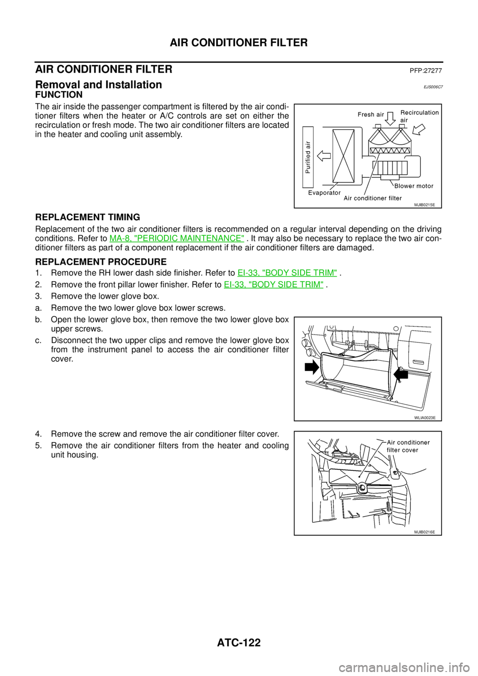
FUNCTION
The air inside the passenger compartment is filtered by the air condi-
tioner filters when the heater or A/C controls are set on either the
recirculation or fresh mode. The two air conditioner filters are located
in the heater and cooling unit assembly.
REPLACEMENT TIMING
Replacement of the two air conditioner filters is recommended on a regular interval depending on the driving
conditions. Refer toMA-8, "
PERIODIC MAINTENANCE". It may also be necessary to replace the two air con-
ditioner filters as part of a component replacement if the air conditioner filters are damaged.
REPLACEMENT PROCEDURE
1. Remove the RH lower dash side finisher. Refer toEI-33, "BODY SIDE TRIM".
2. Remove the front pillar lower finisher. Refer toEI-33, "
BODY SIDE TRIM".
3. Remove the lower glove box.
a. Remove the two lower glove box lower screws.
b. Open the lower glove box, then remove the two lower glove box
upper screws.
c. Disconnect the two upper clips and remove the lower glove box
from the instrument panel to access the air conditioner filter
cover.
4. Remove the screw and remove the air conditioner filter cover.
5. Remove the air conditioner filters from the heater and cooling
unit housing.
MJIB0215E
WLIA0023E
MJIB0216E
Page 463 of 3171
INTAKE DOOR MOTOR
ATC-129
C
D
E
F
G
H
I
K
L
MA
B
AT C
INTAKE DOOR MOTORPFP:27730
ComponentsEJS006CD
Intake Door Motor - Heater and Cooling Unit Assembly
NOTE:
This illustration is for LHD models. The layout for RHD models is symmetrically opposite.
Removal and InstallationEJS006DD
REMOVAL
1. Remove the heater and cooling unit assembly. Refer toATC-124, "HEATER&COOLING UNIT ASSEM-
BLY".
2. Remove the steering member from the heater and cooling unit assembly.
3. Disconnect the intake door motor electrical connector.
4. Remove the three screws and remove the intake door motor.
INSTALLATION
Installation is in the reverse order of removal.
1. Heater and cooling unit assembly 2. Intake door motor 3. Air mix door motor (driver)
4. Variable blower control 5. Air mix door motor (passenger) 6. Mode door motor
LBIA0415E
Page 464 of 3171
ATC-130
MODE DOOR MOTOR
MODE DOOR MOTOR
PFP:27731
ComponentsEJS006CE
Mode Door Motor - Heater and Cooling Unit Assembly
NOTE:
This illustration is for LHD models. The layout for RHD models is symmetrically opposite.
Removal and InstallationEJS006DE
REMOVAL
1. Remove the instrument panel side finisher. Refer toIP-10, "INSTRUMENT PANEL ASSEMBLY".
2. Remove the lower instrument cover. Refer toIP-10, "
INSTRUMENT PANEL ASSEMBLY".
3. Disconnect the mode door motor electrical connector.
4. Remove the three screws and remove the mode door motor.
INSTALLATION
Installation is in the reverse order of removal.
1. Heater and cooling unit assembly 2. Intake door motor 3. Air mix door motor (driver)
4. Variable blower control 5. Air mix door motor (passenger) 6. Mode door motor
LBIA0415E
Page 465 of 3171

AIR MIX DOOR MOTOR
ATC-131
C
D
E
F
G
H
I
K
L
MA
B
AT C
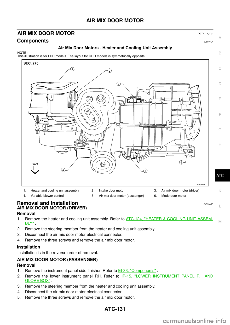
AIR MIX DOOR MOTORPFP:27732
ComponentsEJS006CF
Air Mix Door Motors - Heater and Cooling Unit Assembly
NOTE:
This illustration is for LHD models. The layout for RHD models is symmetrically opposite.
Removal and InstallationEJS006CG
AIR MIX DOOR MOTOR (DRIVER)
Removal
1. Remove the heater and cooling unit assembly. Refer toATC-124, "HEATER&COOLING UNIT ASSEM-
BLY".
2. Remove the steering member from the heater and cooling unit assembly.
3. Disconnect the air mix door motor electrical connector.
4. Remove the three screws and remove the air mix door motor.
Installation
Installation is in the reverse order of removal.
AIR MIX DOOR MOTOR (PASSENGER)
Removal
1. Remove the instrument panel side finisher. Refer toEI-33, "Components".
2. Remove the lower instrument panel RH. Refer toIP-15, "
LOWER INSTRUMENT PANEL RH AND
GLOVE BOX".
3. Remove the steering member from the heater and cooling unit assembly.
4. Disconnect the air mix door motor electrical connector.
5. Remove the three screws and remove the air mix door motor.
1. Heater and cooling unit assembly 2. Intake door motor 3. Air mix door motor (driver)
4. Variable blower control 5. Air mix door motor (passenger) 6. Mode door motor
LBIA0415E
Page 467 of 3171
VARIABLE BLOWER CONTROL
ATC-133
C
D
E
F
G
H
I
K
L
MA
B
AT C
VARIABLE BLOWER CONTROLPFP:27200
ComponentsEJS006CH
Variable Blower Control - Heater and Cooling Unit Assembly
NOTE:
This illustration is for LHD models. The layout for RHD models is symmetrically opposite.
Removal and InstallationEJS006DF
REMOVAL
1. Disconnect the variable blower control electrical connector.
2. Remove the two screws and remove the variable blower control.
INSTALLATION
Installation is in the reverse order of removal.
1. Heater and cooling unit assembly 2. Intake door motor 3. Air mix door motor (driver)
4. Variable blower control 5. Air mix door motor (passenger) 6. Mode door motor
LBIA0415E
Page 483 of 3171
REFRIGERANT LINES
ATC-149
C
D
E
F
G
H
I
K
L
MA
B
AT C
Removal and Installation for EvaporatorEJS006CX
Heater and Cooling Unit Assembly
REMOVAL
1. Remove the heater core. Refer toATC-127, "REMOVAL".
2. Separate the heater and cooling unit case.
3. Remove the evaporator.
INSTALLATION
Installation is in the reverse order of removal.
MJIB0214E
1. Center ventilator connector duct 2. Heater core cover 3. Intake air case
4. Heater core and evaporator pipes
bracket5. Heater core and evaporator pipes
grommet6. Heater core
7. Upper heater and cooling unit case 8. Expansion valve 9. Evaporator
10. Lower heater and cooling unit case 11. Variable blower control 12. Blower motor