Page 339 of 3171
PRECAUTIONS
ATC-5
C
D
E
F
G
H
I
K
L
MA
B
AT C
lIf the vehicle is within the warranty period, the air conditioner warranty is void. Please contact NISSAN
Customer Affairs for further assistance.
General Refrigerant PrecautionsEJS006AN
WARNING:
lDo not release refrigerant into the air. Use approved recovery/recycling equipment to capture the
refrigerant every time an air conditioning system is discharged.
lAlways wear eye and hand protection (goggles and gloves) when working with any refrigerant or
air conditioning system.
lDo not store or heat refrigerant containers above 52°C.
lDo not heat a refrigerant container with an open flame; if container warming is required, place the
bottom of the container in a warm pail of water.
lDo not intentionally drop, puncture, or incinerate refrigerant containers.
lKeep refrigerant away from open flames: poisonous gas will be produced if refrigerant burns.
lRefrigerant will displace oxygen, therefore be certain to work in well ventilated areas to prevent
suffocation.
lDo not pressure test or leak test HFC-134a (R-134a) service equipment and/or vehicle air condi-
tioning systems with compressed air during repair. Some mixtures of air and HFC-134a (R-134a)
have been shown to be combustible at elevated pressures. These mixtures, if ignited, may cause
injury or property damage. Additional health and safety information may be obtained from refriger-
ant manufacturers.
Precautions for Refrigerant ConnectionEJS006AO
A new type refrigerant connection has been introduced to all refrigerant lines except the following locations.
lExpansion valve to cooling unit
lEvaporator pipes to evaporator (inside cooling unit)
lRefrigerant pressure sensor
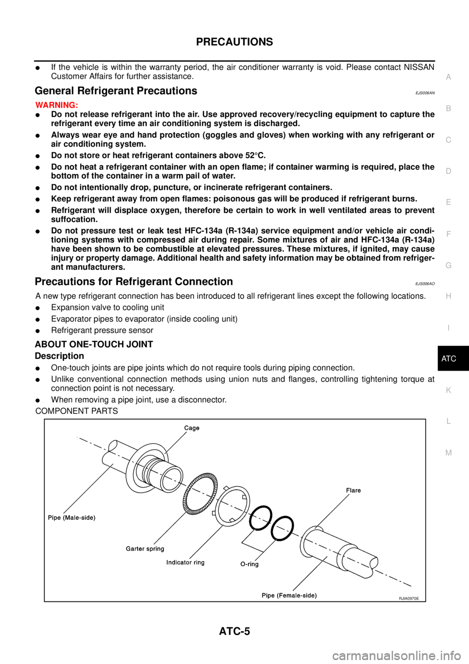
ABOUT ONE-TOUCH JOINT
Description
lOne-touch joints are pipe joints which do not require tools during piping connection.
lUnlike conventional connection methods using union nuts and flanges, controlling tightening torque at
connection point is not necessary.
lWhen removing a pipe joint, use a disconnector.
COMPONENT PARTS
RJIA0970E
Page 367 of 3171
TROUBLE DIAGNOSIS
ATC-33
C
D
E
F
G
H
I
K
L
MA
B
AT C
TROUBLE DIAGNOSISPFP:00004
CONSULT-II Function (BCM)EJS006B8
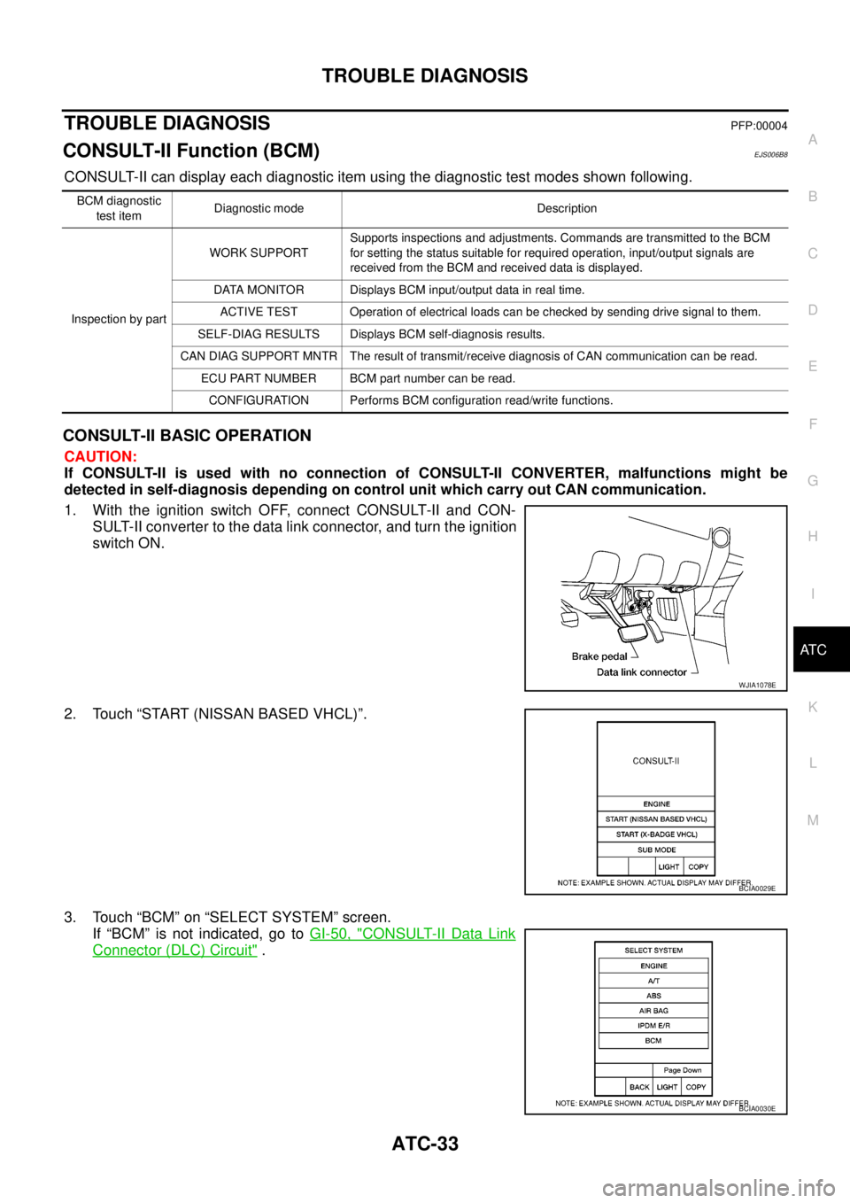
CONSULT-II can display each diagnostic item using the diagnostic test modes shown following.
CONSULT-II BASIC OPERATION
CAUTION:
If CONSULT-II is used with no connection of CONSULT-II CONVERTER, malfunctions might be
detected in self-diagnosis depending on control unit which carry out CAN communication.
1. With the ignition switch OFF, connect CONSULT-II and CON-
SULT-II converter to the data link connector, and turn the ignition
switch ON.
2. Touch “START (NISSAN BASED VHCL)”.
3. Touch “BCM” on “SELECT SYSTEM” screen.
If “BCM” is not indicated, go toGI-50, "
CONSULT-II Data Link
Connector (DLC) Circuit".
BCM diagnostic
test itemDiagnostic mode Description
Inspection by partWORK SUPPORTSupports inspections and adjustments. Commands are transmitted to the BCM
for setting the status suitable for required operation, input/output signals are
received from the BCM and received data is displayed.
DATA MONITOR Displays BCM input/output data in real time.
ACTIVE TEST Operation of electrical loads can be checked by sending drive signal to them.
SELF-DIAG RESULTS Displays BCM self-diagnosis results.
CAN DIAG SUPPORT MNTR The result of transmit/receive diagnosis of CAN communication can be read.
ECU PART NUMBER BCM part number can be read.
CONFIGURATION Performs BCM configuration read/write functions.
WJIA1078E
BCIA0029E
BCIA0030E
Page 395 of 3171
TROUBLE DIAGNOSIS
ATC-61
C
D
E
F
G
H
I
K
L
MA
B
AT C
COMPONENT DESCRIPTION
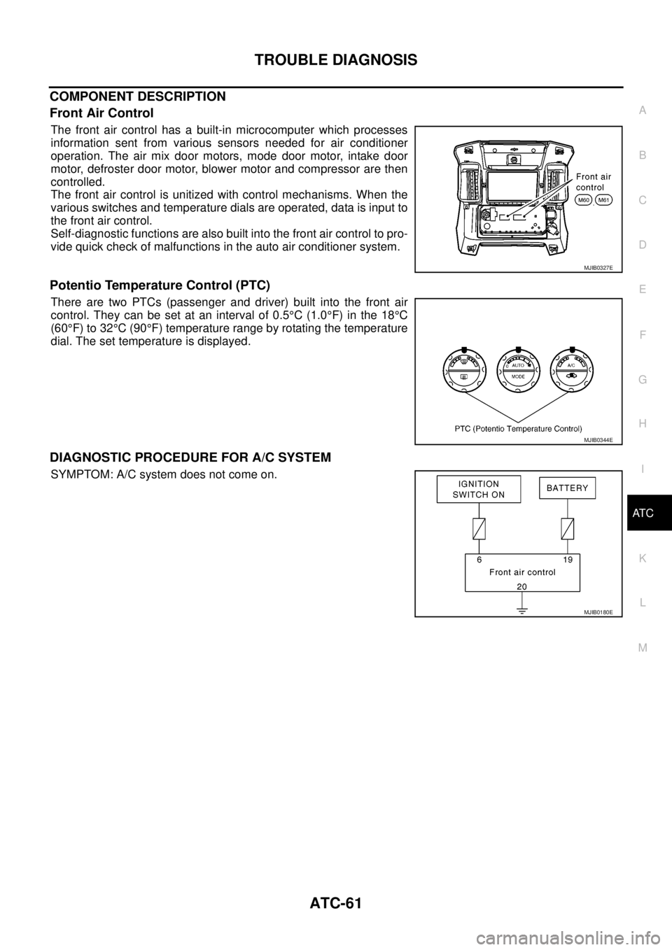
Front Air Control
The front air control has a built-in microcomputer which processes
information sent from various sensors needed for air conditioner
operation. The air mix door motors, mode door motor, intake door
motor, defroster door motor, blower motor and compressor are then
controlled.
The front air control is unitized with control mechanisms. When the
various switches and temperature dials are operated, data is input to
the front air control.
Self-diagnostic functions are also built into the front air control to pro-
vide quick check of malfunctions in the auto air conditioner system.
Potentio Temperature Control (PTC)
There are two PTCs (passenger and driver) built into the front air
control. They can be set at an interval of 0.5°C(1.0°F) in the 18°C
(60°F) to 32°C(90°F) temperature range by rotating the temperature
dial. The set temperature is displayed.
DIAGNOSTIC PROCEDURE FOR A/C SYSTEM
SYMPTOM: A/C system does not come on.
MJIB0327E
MJIB0344E
MJIB0180E
Page 399 of 3171
TROUBLE DIAGNOSIS
ATC-65
C
D
E
F
G
H
I
K
L
MA
B
AT C
COMPONENT DESCRIPTION
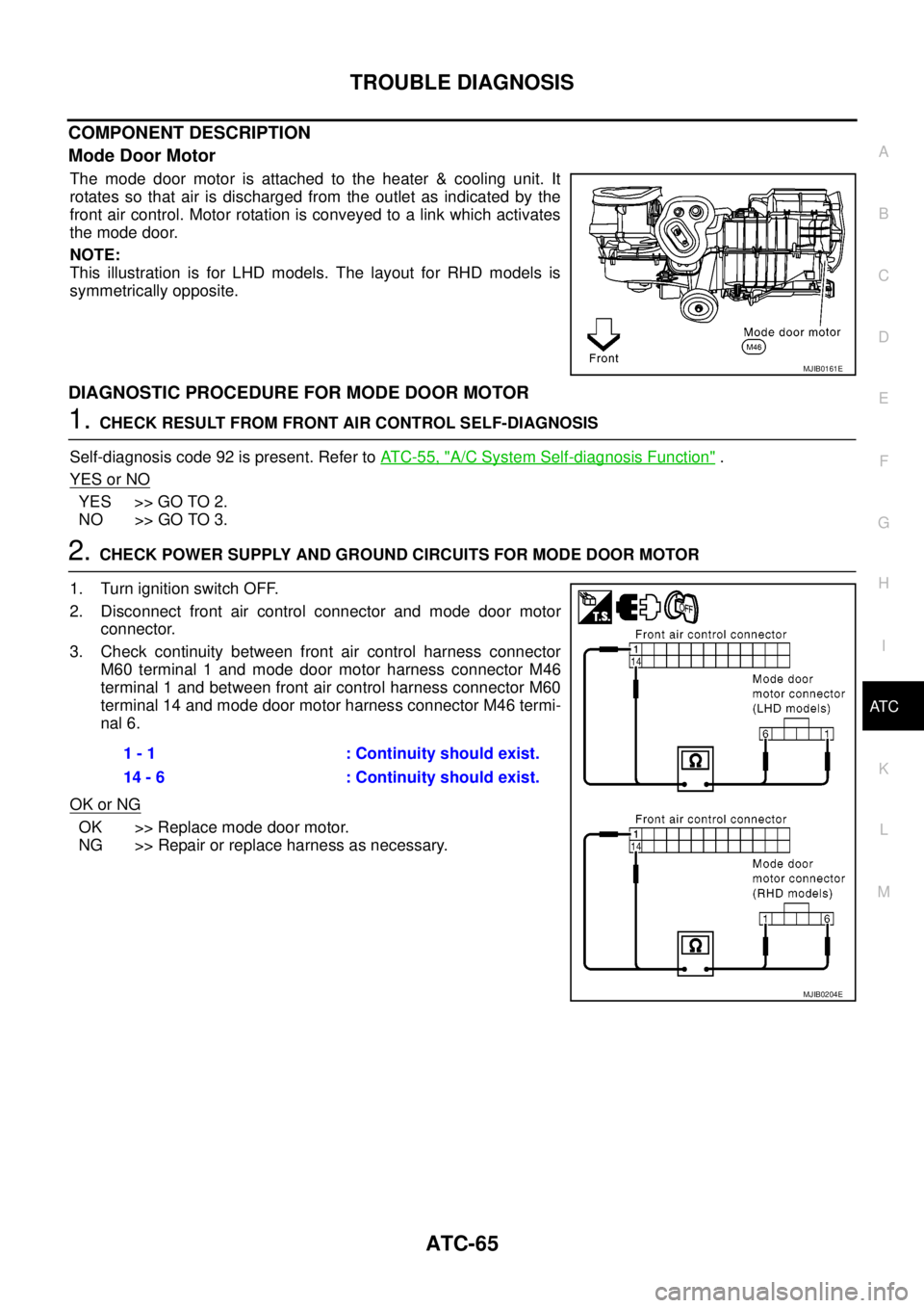
Mode Door Motor
The mode door motor is attached to the heater & cooling unit. It
rotates so that air is discharged from the outlet as indicated by the
front air control. Motor rotation is conveyed to a link which activates
themodedoor.
NOTE:
This illustration is for LHD models. The layout for RHD models is
symmetrically opposite.
DIAGNOSTIC PROCEDURE FOR MODE DOOR MOTOR
1.CHECK RESULT FROM FRONT AIR CONTROL SELF-DIAGNOSIS
Self-diagnosis code 92 is present. Refer toAT C - 5 5 , "
A/C System Self-diagnosis Function".
YES or NO
YES >> GO TO 2.
NO >> GO TO 3.
2.CHECK POWER SUPPLY AND GROUND CIRCUITS FOR MODE DOOR MOTOR
1. Turn ignition switch OFF.
2. Disconnect front air control connector and mode door motor
connector.
3. Check continuity between front air control harness connector
M60 terminal 1 and mode door motor harness connector M46
terminal 1 and between front air control harness connector M60
terminal 14 and mode door motor harness connector M46 termi-
nal 6.
OK or NG
OK >> Replace mode door motor.
NG >> Repair or replace harness as necessary.
MJIB0161E
1 - 1 : Continuity should exist.
14 - 6 : Continuity should exist.
MJIB0204E
Page 404 of 3171
ATC-70
TROUBLE DIAGNOSIS
COMPONENT DESCRIPTION
Air Mix Door Motors
The driver and passenger air mix door motors are attached to the
heater & cooling unit. These motors rotate so that the air mix door is
opened or closed to a position set by the front air control. Motor rota-
tion is then conveyed through a shaft and the air mix door position is
then fed back to the front air control by the PBR built into the air mix
door motors.
NOTE:
The illustrations for air mix door motors (driver and passenger) are
for LHD models. The layout for RHD models is symmetrically oppo-
site.
MJIB0162E
MJIB0163E
Page 413 of 3171
TROUBLE DIAGNOSIS
ATC-79
C
D
E
F
G
H
I
K
L
MA
B
AT C
COMPONENT DESCRIPTION
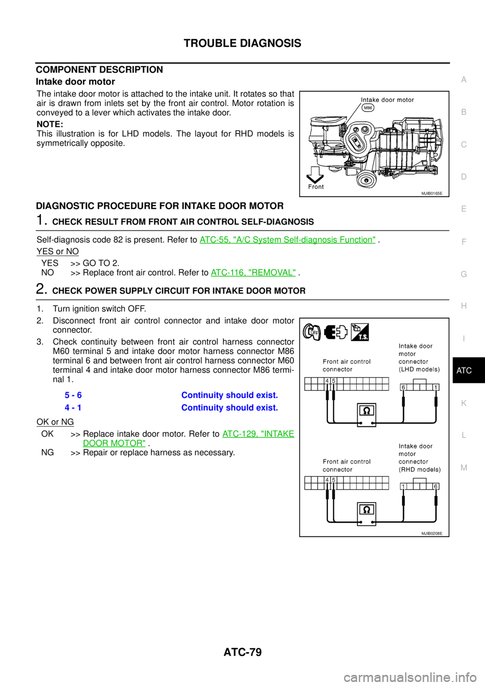
Intake door motor
The intake door motor is attached to the intake unit. It rotates so that
air is drawn from inlets set by the front air control. Motor rotation is
conveyed to a lever which activates the intake door.
NOTE:
This illustration is for LHD models. The layout for RHD models is
symmetrically opposite.
DIAGNOSTIC PROCEDURE FOR INTAKE DOOR MOTOR
1.CHECK RESULT FROM FRONT AIR CONTROL SELF-DIAGNOSIS
Self-diagnosis code 82 is present. Refer toAT C - 5 5 , "
A/C System Self-diagnosis Function".
YES or NO
YES >> GO TO 2.
NO >> Replace front air control. Refer toAT C - 11 6 , "
REMOVAL".
2.CHECK POWER SUPPLY CIRCUIT FOR INTAKE DOOR MOTOR
1. Turn ignition switch OFF.
2. Disconnect front air control connector and intake door motor
connector.
3. Check continuity between front air control harness connector
M60 terminal 5 and intake door motor harness connector M86
terminal 6 and between front air control harness connector M60
terminal 4 and intake door motor harness connector M86 termi-
nal 1.
OK or NG
OK >> Replace intake door motor. Refer toATC-129, "INTAKE
DOOR MOTOR".
NG >> Repair or replace harness as necessary.
MJIB0165E
5 - 6 Continuity should exist.
4 - 1 Continuity should exist.
MJIB0208E
Page 416 of 3171
ATC-82
TROUBLE DIAGNOSIS
Blower Speed Compensation - Sunload
When the in-vehicle temperature and the set temperature are very close, the blower will be operating at low
speed. The speed will vary depending on the sunload. During conditions of low or no sunload, the blower
operates at low speed. During high sunload conditions, the front air control causes the blower speed to
increase.
Blower Speed Control Specification
COMPONENT DESCRIPTION
Variable Blower Control
The variable blower control is located on the cooling unit. The vari-
able blower control receives a gate voltage from the front air control
to steplessly maintain the blower motor voltage in the 0 to 5 volt
range (approx.).
NOTE:
This illustration is for LHD models. The layout for RHD models is
symmetrically opposite.
DIAGNOSTIC PROCEDURE FOR BLOWER MOTOR
SYMPTOM: Blower motor operation is malfunctioning under starting
blower speed control.
WJIA0441E
MJIB0166E
MJIB0064E
Page 448 of 3171
ATC-114
TROUBLE DIAGNOSIS
Intake Sensor Circuit
EJS006BZ
COMPONENT DESCRIPTION
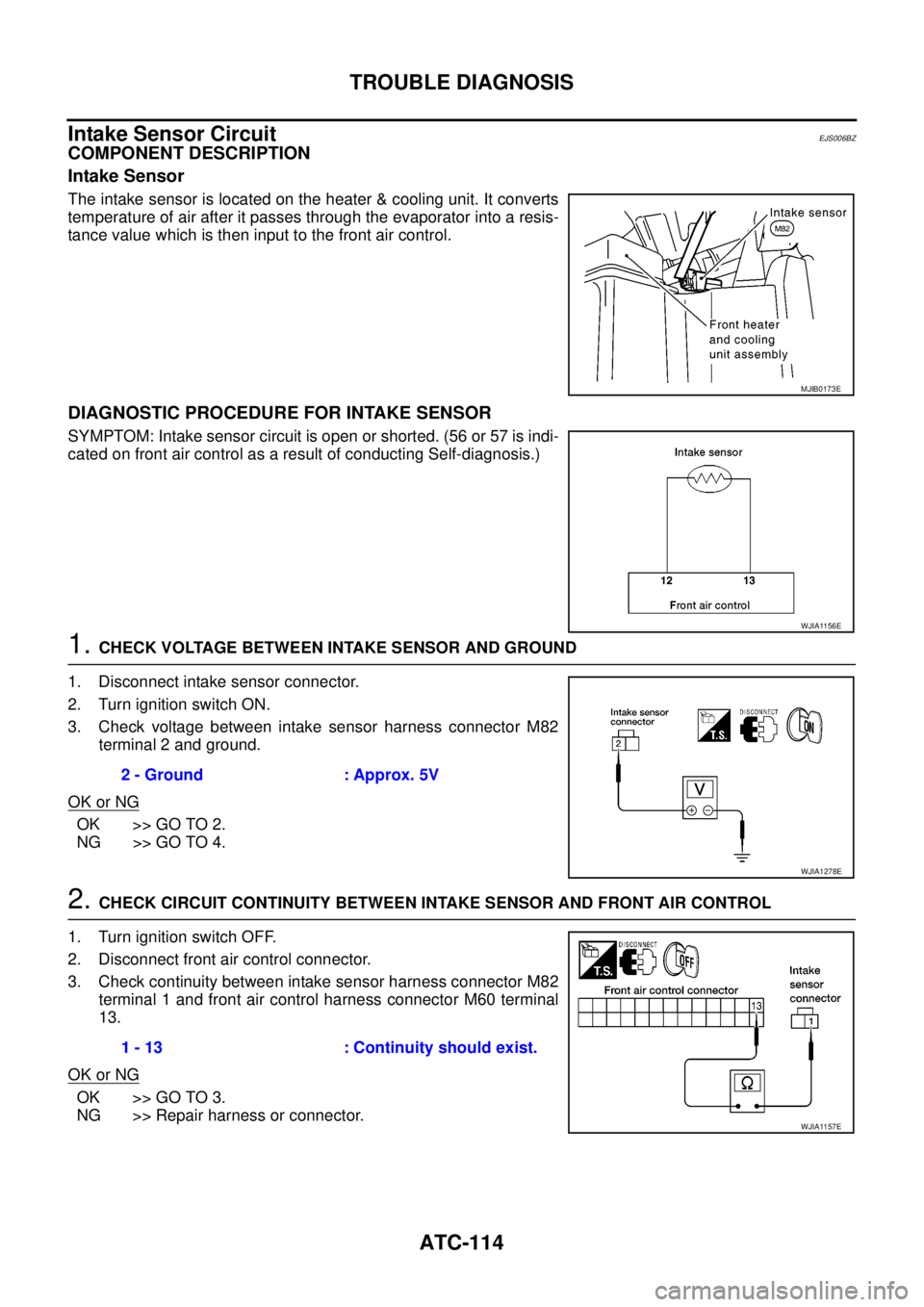
Intake Sensor
The intake sensor is located on the heater & cooling unit. It converts
temperature of air after it passes through the evaporator into a resis-
tance value which is then input to the front air control.
DIAGNOSTIC PROCEDURE FOR INTAKE SENSOR
SYMPTOM: Intake sensor circuit is open or shorted. (56 or 57 is indi-
cated on front air control as a result of conducting Self-diagnosis.)
1.CHECK VOLTAGE BETWEEN INTAKE SENSOR AND GROUND
1. Disconnect intake sensor connector.
2. Turn ignition switch ON.
3. Check voltage between intake sensor harness connector M82
terminal 2 and ground.
OK or NG
OK >> GO TO 2.
NG >> GO TO 4.
2.CHECK CIRCUIT CONTINUITY BETWEEN INTAKE SENSOR AND FRONT AIR CONTROL
1. Turn ignition switch OFF.
2. Disconnect front air control connector.
3. Check continuity between intake sensor harness connector M82
terminal 1 and front air control harness connector M60 terminal
13.
OK or NG
OK >> GO TO 3.
NG >> Repair harness or connector.
MJIB0173E
WJIA1156E
2 - Ground : Approx. 5V
WJIA1278E
1 - 13 : Continuity should exist.
WJIA1157E