2005 NISSAN NAVARA control unit
[x] Cancel search: control unitPage 1765 of 3171

IP-6
SQUEAK AND RATTLE TROUBLE DIAGNOSES
Generic Squeak and Rattle Troubleshooting
EIS00DYX
Refer to Table of Contents for specific component removal and installation information.
INSTRUMENT PANEL
Most incidents are caused by contact and movement between:
1. The cluster lid A and instrument panel
2. Acrylic lens and combination meter housing
3. Instrument panel to front pillar garnish
4. Instrument panel to windshield
5. Instrument panel mounting pins
6. Wiring harnesses behind the combination meter
7. A/C defroster duct and duct joint
These incidents can usually be located by tapping or moving the components to duplicate the noise or by
pressing on the components while driving to stop the noise. Most of these incidents can be repaired by apply-
ing felt cloth tape or silicone spray (in hard to reach areas). Urethane pads can be used to insulate wiring har-
ness.
CAUTION:
Do not use silicone spray to isolate a squeak or rattle. If you saturate the area with silicone, you will
not be able to recheck the repair.
CENTER CONSOLE
Components to pay attention to include:
1. Shifter assembly cover to finisher
2. A/C control unit and cluster lid C
3. Wiring harnesses behind audio and A/C control unit
The instrument panel repair and isolation procedures also apply to the center console.
DOORS
Pay attention to the:
1. Finisher and inner panel making a slapping noise
2. Inside handle escutcheon to door finisher
3. Wiring harnesses tapping
4. Door striker out of alignment causing a popping noise on starts and stops
Tapping or moving the components or pressing on them while driving to duplicate the conditions can isolate
many of these incidents. You can usually insulate the areas with felt cloth tape or insulator foam blocks to
repair the noise.
TRUNK
Trunk noises are often caused by a loose jack or loose items put into the trunk by the owner.
In addition look for:
1. Trunk lid bumpers out of adjustment
2. Trunk lid striker out of adjustment
3. The trunk lid torsion bars knocking together
4. A loose license plate or bracket
Most of these incidents can be repaired by adjusting, securing or insulating the item(s) or component(s) caus-
ing the noise.
Page 1769 of 3171

IP-10
INSTRUMENT PANEL ASSEMBLY
INSTRUMENT PANEL ASSEMBLY
PFP:68200
Removal and InstallationEIS00DYZ
INSTRUMENT PANEL
Removal
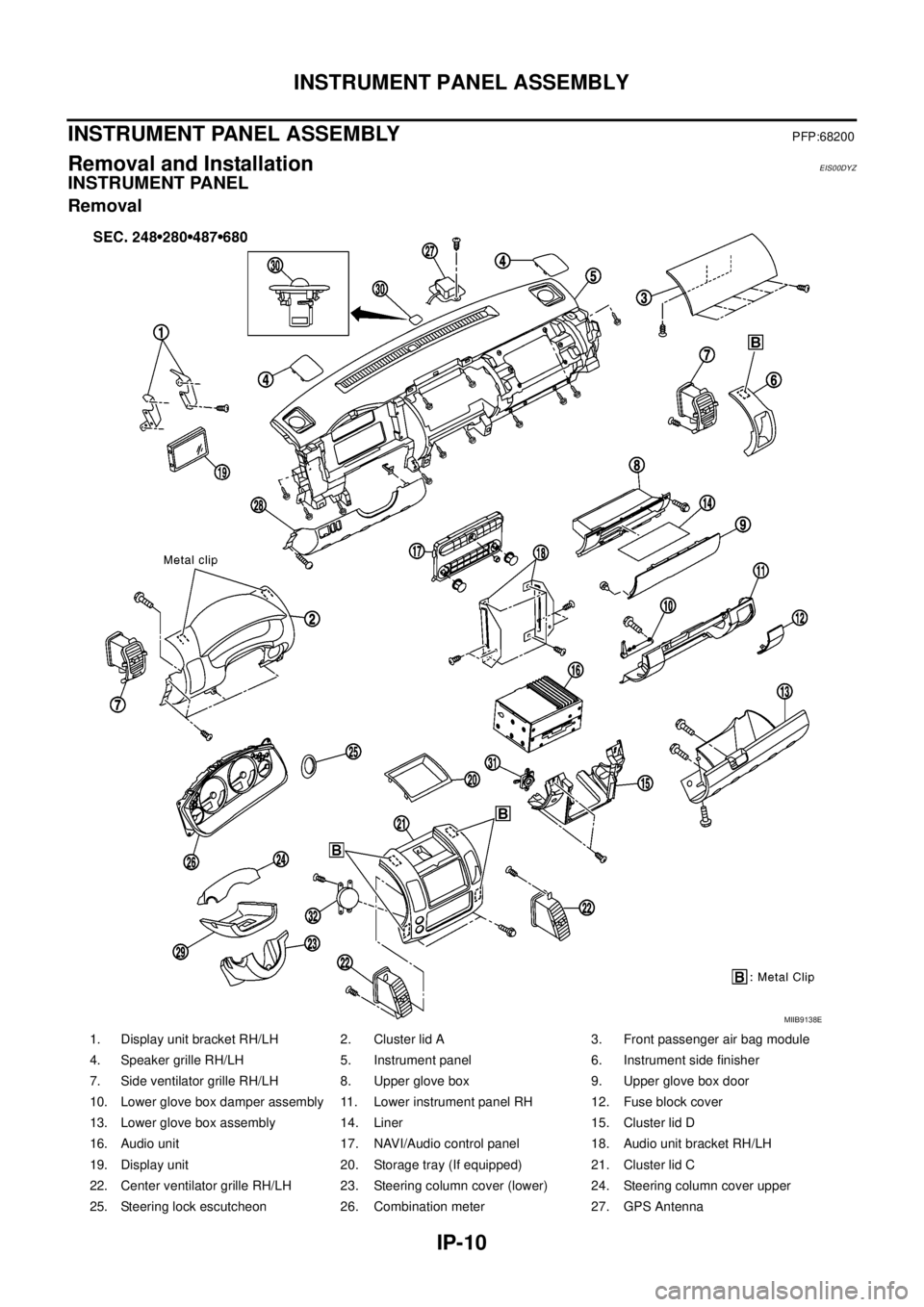
1. Display unit bracket RH/LH 2. Cluster lid A 3. Front passenger air bag module
4. Speaker grille RH/LH 5. Instrument panel 6. Instrument side finisher
7. Side ventilator grille RH/LH 8. Upper glove box 9. Upper glove box door
10. Lower glove box damper assembly 11. Lower instrument panel RH 12. Fuse block cover
13. Lower glove box assembly 14. Liner 15. Cluster lid D
16. Audio unit 17. NAVI/Audio control panel 18. Audio unit bracket RH/LH
19. Display unit 20. Storage tray (If equipped) 21. Cluster lid C
22. Center ventilator grille RH/LH 23. Steering column cover (lower) 24. Steering column cover upper
25. Steering lock escutcheon 26. Combination meter 27. GPS Antenna
MIIB9138E
Page 1778 of 3171

LAN-1
LAN SYSTEM
K ELECTRICAL
CONTENTS
C
D
E
F
G
H
I
J
L
M
SECTIONLAN
A
B
LAN
LAN SYSTEM
CAN
PRECAUTIONS .......................................................... 3
Precautions for Supplemental Restraint System
(SRS)“AIRBAG”and“SEATBELTPRE-TEN-
SIONER” .................................................................. 3
Precautions When Using CONSULT-II ..................... 3
CHECK POINTS FOR USING CONSULT-II ......... 3
Precautions For Trouble Diagnosis .......................... 3
CAN SYSTEM ....................................................... 3
Precautions For Harness Repair .............................. 3
CAN SYSTEM ....................................................... 3
TROUBLE DIAGNOSES WORK FLOW .................... 5
When Displaying CAN Communication System
Errors ....................................................................... 5
WHEN A MALFUNCTION IS DETECTED BY
CAN COMMUNICATION SYSTEM ....................... 5
WHEN A MALFUNCTION IS DETECTED
EXCEPT CAN COMMUNICATION SYSTEM ........ 5
TROUBLE DIAGNOSIS FLOW CHART ............... 6
Diagnosis Procedure ................................................ 7
SELECTING CAN SYSTEM TYPE (HOW TO
USE SPECIFICATION TABLE) ............................. 7
ACQUISITION OF DATA BY CONSULT-II ............ 8
HOW TO USE CHECK SHEET TABLE ................ 9
CAN Diagnostic Support Monitor ........................... 15
DESCRIPTION OF “CAN DIAG SUPPORT
MNTR” SCREEN FOR ECM ............................... 15
DESCRIPTION OF “CAN DIAG SUPPORT
MNTR” SCREEN FOR TCM ............................... 16
DESCRIPTION OF “CAN DIAG SUPPORT
MNTR” SCREEN FOR NAVI CONTROL UNIT ... 17
DESCRIPTION OF “CAN DIAG SUPPORT
MNTR” SCREEN FOR DIFFERENTIAL LOCK
CONTROL UNIT ................................................. 18
DESCRIPTION OF “CAN DIAG SUPPORT
MNTR” SCREEN FOR FRONT AIR CONTROL... 19
DESCRIPTION OF “CAN DIAG SUPPORT
MNTR” SCREEN FOR BCM ............................... 20
DESCRIPTION OF “CAN DIAG SUPPORT
MNTR” SCREEN FOR TRANSFER CONTROLUNIT .................................................................... 21
DESCRIPTION OF “CAN DIAG SUPPORT
MNTR” SCREEN FOR ABS ACTUATOR AND
ELECTRIC UNIT (CONTROL UNIT) ................... 21
DESCRIPTION OF “CAN DIAG SUPPORT
MNTR” SCREEN FOR IPDM E/R ....................... 22
CAN COMMUNICATION ........................................... 23
System Description ................................................. 23
Component Parts and Harness Connector Location... 23
LHD MODELS ..................................................... 23
RHD MODELS .................................................... 24
Schematic ............................................................... 25
Wiring Diagram — CAN — ..................................... 26
CAN Communication Unit ....................................... 30
TYPE 1/ TYPE 2/ TYPE 3 ................................... 32
TYPE 4/ TYPE 5 .................................................. 34
TYPE 6/ TYPE 7/ TYPE 8/ TYPE 9/ TYPE 10/
TYPE 11/ TYPE 16/ TYPE 17 .............................. 36
TYPE 12/ TYPE 13/ TYPE 14/ TYPE 15 ............. 40
CAN SYSTEM (TYPE 1) ........................................... 44
Component Parts and Harness Connector Location... 44
Schematic ............................................................... 44
Wiring Diagram — CAN — ..................................... 44
Check Sheet ........................................................... 45
CHECK SHEET RESULTS (EXAMPLE) ............. 47
CAN SYSTEM (TYPE 2) ........................................... 56
Component Parts and Harness Connector Location... 56
Schematic ............................................................... 56
Wiring Diagram — CAN — ..................................... 56
Check Sheet ........................................................... 57
CHECK SHEET RESULTS (EXAMPLE) ............. 59
CAN SYSTEM (TYPE 3) ........................................... 68
Component Parts and Harness Connector Location... 68
Schematic ............................................................... 68
Wiring Diagram — CAN — ..................................... 68
Check Sheet ........................................................... 69
CHECK SHEET RESULTS (EXAMPLE) ............. 71
CAN SYSTEM (TYPE 4) ........................................... 82
Component Parts and Harness Connector Location... 82
Schematic ............................................................... 82
Page 1779 of 3171

LAN-2
Wiring Diagram — CAN — ..................................... 82
Check Sheet ........................................................... 83
CHECK SHEET RESULTS (EXAMPLE) ............. 85
CAN SYSTEM (TYPE 5) ........................................... 96
Component Parts and Harness Connector Location... 96
Schematic ............................................................... 96
Wiring Diagram — CAN — ..................................... 96
Check Sheet ........................................................... 97
CHECK SHEET RESULTS (EXAMPLE) ............. 99
CAN SYSTEM (TYPE 6) .........................................112
Component Parts and Harness Connector Location.112
Schematic .............................................................112
Wiring Diagram — CAN — ...................................112
Check Sheet .........................................................113
CHECK SHEET RESULTS (EXAMPLE) ...........115
CAN SYSTEM (TYPE 7) .........................................125
Component Parts and Harness Connector Location.125
Schematic .............................................................125
Wiring Diagram — CAN — ...................................125
Check Sheet .........................................................126
CHECK SHEET RESULTS (EXAMPLE) ...........128
CAN SYSTEM (TYPE 8) .........................................139
Component Parts and Harness Connector Location.139
Schematic .............................................................139
Wiring Diagram — CAN — ...................................139
Check Sheet .........................................................140
CHECK SHEET RESULTS (EXAMPLE) ...........142
CAN SYSTEM (TYPE 9) .........................................152
Component Parts and Harness Connector Location.152
Schematic .............................................................152
Wiring Diagram — CAN — ...................................152
Check Sheet .........................................................153
CHECK SHEET RESULTS (EXAMPLE) ...........155
CAN SYSTEM (TYPE 10) .......................................166
Component Parts and Harness Connector Location.166
Schematic .............................................................166
Wiring Diagram — CAN — ...................................166
Check Sheet .........................................................167
CHECK SHEET RESULTS (EXAMPLE) ...........169
CAN SYSTEM (TYPE 11) ........................................181
Component Parts and Harness Connector Location.181
Schematic .............................................................181
Wiring Diagram — CAN — ...................................181
Check Sheet .........................................................182
CHECK SHEET RESULTS (EXAMPLE) ...........185
CAN SYSTEM (TYPE 12) .......................................198
Component Parts and Harness Connector Location.198
Schematic .............................................................198
Wiring Diagram — CAN — ...................................198
Check Sheet .........................................................199
CHECK SHEET RESULTS (EXAMPLE) ...........201
CAN SYSTEM (TYPE 13) .......................................213
Component Parts and Harness Connector Location.213Schematic .............................................................213
Wiring Diagram — CAN — ...................................213
Check Sheet .........................................................214
CHECK SHEET RESULTS (EXAMPLE) ............217
CAN SYSTEM (TYPE 14) ........................................230
Component Parts and Harness Connector Location.230
Schematic .............................................................230
Wiring Diagram — CAN — ...................................230
Check Sheet .........................................................231
CHECK SHEET RESULTS (EXAMPLE) ............234
CAN SYSTEM (TYPE 15) ........................................248
Component Parts and Harness Connector Location.248
Schematic .............................................................248
Wiring Diagram — CAN — ...................................248
Check Sheet .........................................................249
CHECK SHEET RESULTS (EXAMPLE) ............252
CAN SYSTEM (TYPE 16) ........................................267
Component Parts and Harness Connector Location.267
Schematic .............................................................267
Wiring Diagram — CAN — ...................................267
Check Sheet .........................................................268
CHECK SHEET RESULTS (EXAMPLE) ............270
CAN SYSTEM (TYPE 17) ........................................279
Component Parts and Harness Connector Location.279
Schematic .............................................................279
Wiring Diagram — CAN — ...................................279
Check Sheet .........................................................280
CHECK SHEET RESULTS (EXAMPLE) ............282
TROUBLE DIAGNOSIS FOR SYSTEM ..................292
Inspection Between TCM and Data Link Connector
Circuit ....................................................................292
Inspection Between TCM and NAVI Control Unit Cir-
cuit ........................................................................293
Inspection Between NAVI Control Unit and Data
Link Connector Circuit ...........................................295
Inspection Between Data Link Connector and ABS
Actuator and Electric Unit (Control Unit) Circuit ....296
ECM Circuit Inspection for M/T Models ................297
ECM Circuit Inspection for A/T Models .................298
TCM Circuit Inspection ..........................................298
NAVI Control Unit Circuit Inspection .....................299
Differential Lock Control Unit Circuit Inspection ....299
Front Air Control Circuit Inspection .......................300
Data Link Connector Circuit Inspection .................300
BCM Circuit Inspection .........................................301
Combination Meter Circuit Inspection ...................301
Transfer Control Unit Circuit Inspection ................302
ABS Actuator and Electric Unit (Control Unit) Circuit
Inspection ..............................................................302
IPDM E/R Circuit Inspection .................................303
CAN Communication Circuit Inspection ................303
IPDM E/R Ignition Relay Circuit Inspection ...........304
Page 1780 of 3171
![NISSAN NAVARA 2005 Repair Workshop Manual PRECAUTIONS
LAN-3
[CAN]
C
D
E
F
G
H
I
J
L
MA
B
LAN
[CAN]PRECAUTIONSPFP:00001
Precautions for Supplemental Restraint System (SRS) “AIR BAG” and “SEAT
BELT PRE-TENSIONER”
EKS00Q9Y
The Supplement NISSAN NAVARA 2005 Repair Workshop Manual PRECAUTIONS
LAN-3
[CAN]
C
D
E
F
G
H
I
J
L
MA
B
LAN
[CAN]PRECAUTIONSPFP:00001
Precautions for Supplemental Restraint System (SRS) “AIR BAG” and “SEAT
BELT PRE-TENSIONER”
EKS00Q9Y
The Supplement](/manual-img/5/57362/w960_57362-1779.png)
PRECAUTIONS
LAN-3
[CAN]
C
D
E
F
G
H
I
J
L
MA
B
LAN
[CAN]PRECAUTIONSPFP:00001
Precautions for Supplemental Restraint System (SRS) “AIR BAG” and “SEAT
BELT PRE-TENSIONER”
EKS00Q9Y
The Supplemental Restraint System such as “AIR BAG” and “SEAT BELT PRE-TENSIONER”, used along
with a front seat belt, helps to reduce the risk or severity of injury to the driver and front passenger for certain
types of collision. Information necessary to service the system safely is included in the SRS and SB section of
this Service Manual.
WARNING:
lTo avoid rendering the SRS inoperative, which could increase the risk of personal injury or death
in the event of a collision which would result in air bag inflation, all maintenance must be per-
formed by an authorized NISSAN/INFINITI dealer.
lImproper maintenance, including incorrect removal and installation of the SRS, can lead to per-
sonal injury caused by unintentional activation of the system. For removal of Spiral Cable and Air
Bag Module, see the SRS section.
lDo not use electrical test equipment on any circuit related to the SRS unless instructed to in this
Service Manual. SRS wiring harnesses can be identified by yellow and/or orange harnesses or
harness connectors.
Precautions When Using CONSULT-IIEKS00LBE
When connecting CONSULT-II to data link connector, connect them through CONSULT-II CONVERTER.
CAUTION:
If CONSULT-II is used with no connection of CONSULT-II CONVERTER, malfunctions might be
detected in self-diagnosis depending on control unit which carry out CAN communication.
CHECK POINTS FOR USING CONSULT-II
1. Has CONSULT-II been used without connecting CONSULT-II CONVERTER on this vehicle?
–If YES, GO TO 2.
–If NO, GO TO 5.
2. Is there any indication other than indications relating to CAN communication system in the self-diagnosis
results?
–If YES, GO TO 3.
–If NO, GO TO 4.
3. Based on self-diagnosis results unrelated to CAN communication, carry out the inspection.
4. Malfunctions may be detected in self-diagnosis depending on control units carrying out CAN communica-
tion. Therefore, erase the self-diagnosis results.
5. Diagnose CAN communication system. Refer toLAN-5, "
TROUBLE DIAGNOSES WORK FLOW".
Precautions For Trouble DiagnosisEKS00LBF
CAN SYSTEM
lDo not apply voltage of 7.0 V or higher to the measurement terminals.
lUse the tester with its open terminal voltage being 7.0 V or less.
lBe sure to turn ignition switch off and disconnect negative battery terminal before checking the circuit.
Precautions For Harness RepairEKS00LBG
CAN SYSTEM
lSolder the repaired parts, and wrap with tape. [Frays of twisted
line must be within 110 mm (4.33 in).]
PKIA0306E
Page 1793 of 3171
![NISSAN NAVARA 2005 Repair Workshop Manual LAN-16
[CAN]
TROUBLE DIAGNOSES WORK FLOW
DESCRIPTION OF “CAN DIAG SUPPORT MNTR” SCREEN
FOR TCM
Display Results (Present)
lOK: Normal
lNG: Malfunction
lUNKWN: The diagnosed unit does not transmit o NISSAN NAVARA 2005 Repair Workshop Manual LAN-16
[CAN]
TROUBLE DIAGNOSES WORK FLOW
DESCRIPTION OF “CAN DIAG SUPPORT MNTR” SCREEN
FOR TCM
Display Results (Present)
lOK: Normal
lNG: Malfunction
lUNKWN: The diagnosed unit does not transmit o](/manual-img/5/57362/w960_57362-1792.png)
LAN-16
[CAN]
TROUBLE DIAGNOSES WORK FLOW
DESCRIPTION OF “CAN DIAG SUPPORT MNTR” SCREEN
FOR TCM
Display Results (Present)
lOK: Normal
lNG: Malfunction
lUNKWN: The diagnosed unit does not transmit or receive the applicable data normally.
SKIB2335E
“SELECT SYSTEM”
screen“CAN DIAG SUPPORT
MNTR” screenDescription Present
A/TINITIAL DIAG Make sure that microcomputer in ECU works normally. OK/NG
TRANSMIT DIAG Make sure of normal transmission. OK/UNKWN
ECM Make sure of normal reception from ECM. OK/UNKWN
VDC/TCS/ABS VDC/TCS/ABS is not diagnosed. OK
METER/M&A Make sure of normal reception from combination meter. OK/UNKWN
ICC/e4WD ICC/e4WD is not diagnosed. UNKWN
AWD/4WD Make sure of normal reception from transfer control unit. OK/UNKWN
Page 1794 of 3171
![NISSAN NAVARA 2005 Repair Workshop Manual TROUBLE DIAGNOSES WORK FLOW
LAN-17
[CAN]
C
D
E
F
G
H
I
J
L
MA
B
LAN
DESCRIPTION OF “CAN DIAG SUPPORT MNTR” SCREEN
FOR NAVI CONTROL UNIT
Display Results (Present)
lOK: Normal
lUNKWN: The diagnosed NISSAN NAVARA 2005 Repair Workshop Manual TROUBLE DIAGNOSES WORK FLOW
LAN-17
[CAN]
C
D
E
F
G
H
I
J
L
MA
B
LAN
DESCRIPTION OF “CAN DIAG SUPPORT MNTR” SCREEN
FOR NAVI CONTROL UNIT
Display Results (Present)
lOK: Normal
lUNKWN: The diagnosed](/manual-img/5/57362/w960_57362-1793.png)
TROUBLE DIAGNOSES WORK FLOW
LAN-17
[CAN]
C
D
E
F
G
H
I
J
L
MA
B
LAN
DESCRIPTION OF “CAN DIAG SUPPORT MNTR” SCREEN
FOR NAVI CONTROL UNIT
Display Results (Present)
lOK: Normal
lUNKWN: The diagnosed unit does not transmit or receive the applicable data normally.
l–: There is no received unit or the unit is not in the condition that reception diagnosis is performed.
Display Results (Past)
lOK: Normal
l0: There is malfunction now.
l1 ~ 39: Displays when it is normal at present and finds malfunction in the past. It increases like 0®1®2...38®39 after returning to the
normal condition whenever IGN OFF®ON. If it is over 39, it is fixed to 39 until the self-diagnostic results are erased. It returns to 0
when malfunction is detected again in the process.
l–: Undiagnosed
SKIB4715E
“SELECT SYSTEM”
screen“CAN DIAG SUP-
PORT MNTR”
screenDescription Present Past
MULTI AVTRANSMIT DIAG TRANSMIT DIAG is not diagnosed. –
OK/0/1~39/– ECM Make sure of normal reception from ECM. OK/UNKWN/–
METER/M&A Make sure of normal reception from combination meter. OK/UNKWN/–
BCM/SEC BCM/SEC is not diagnosed. –
HVAC HVAC is not diagnosed. –
IPDM E/R IPDM E/R is not diagnosed. –
TIRE-P TIRE-P is not diagnosed. –
Page 1795 of 3171
![NISSAN NAVARA 2005 Repair Workshop Manual LAN-18
[CAN]
TROUBLE DIAGNOSES WORK FLOW
DESCRIPTION OF “CAN DIAG SUPPORT MNTR” SCREEN
FOR DIFFERENTIAL LOCK CONTROL UNIT
Display Results (Present)
lOK: Normal
lNG: Malfunction
lUNKWN: The diagnos NISSAN NAVARA 2005 Repair Workshop Manual LAN-18
[CAN]
TROUBLE DIAGNOSES WORK FLOW
DESCRIPTION OF “CAN DIAG SUPPORT MNTR” SCREEN
FOR DIFFERENTIAL LOCK CONTROL UNIT
Display Results (Present)
lOK: Normal
lNG: Malfunction
lUNKWN: The diagnos](/manual-img/5/57362/w960_57362-1794.png)
LAN-18
[CAN]
TROUBLE DIAGNOSES WORK FLOW
DESCRIPTION OF “CAN DIAG SUPPORT MNTR” SCREEN
FOR DIFFERENTIAL LOCK CONTROL UNIT
Display Results (Present)
lOK: Normal
lNG: Malfunction
lUNKWN: The diagnosed unit does not transmit or receive the applicable data normally.
PKIB7196E
“SELECT SYSTEM”
screen“CAN DIAG SUPPORT
MNTR” screenDescription Present
DIFF LOCKINITIAL DIAG Make sure that microcomputer in ECU works normally. OK/NG
TRANSMIT DIAG Make sure of normal transmission. OK/UNKWN
ECM Make sure of normal reception from ECM. OK/UNKWN
VDC/TCS/ABSMake sure of normal reception from ABS actuator and electric unit
(control unit).OK/UNKWN
AWD/4WD Make sure of normal reception from transfer control unit. OK/UNKWN