Page 3588 of 4770
Z18551
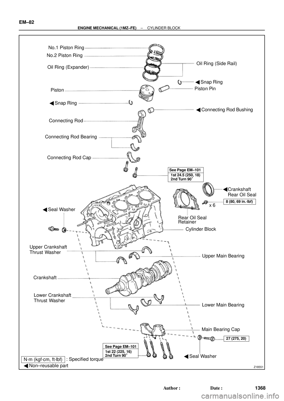
No.1 Piston Ring
Oil Ring (Expander)
PistonPiston Pin No.2 Piston Ring
Oil Ring (Side Rail)
� Snap Ring
� Connecting Rod Bushing � Snap Ring
Connecting Rod
Connecting Rod Bearing
Connecting Rod Cap
1st 24.5 (250, 18)
2nd Turn 90° See Page EM±101
� Seal Washer
Rear Oil Seal
Retainer
Cylinder Block
Upper Main Bearing
Lower Main Bearing
Main Bearing Cap Upper Crankshaft
Thrust Washer
Crankshaft
Lower Crankshaft
Thrust Washer
8 (80, 69 in.´lbf)x 6
1st 22 (225, 16)
2nd Turn 90° See Page EM±101
� Seal Washer
27 (275, 20)
N´m (kgf´cm, ft´lbf): Specified torque
� Non±reusable part
Crankshaft
Rear Oil Seal � EM±82
± ENGINE MECHANICAL (1MZ±FE)CYLINDER BLOCK
1368 Author�: Date�:
Page 3592 of 4770
CYLINDER BLOCK
1372 Author�: Date�:
(g) Install the connecting rod cap with the 2 bolts.
(See page EM±101)
Tor")
P12697
P12698
P14127
Number Mark
Number
Mark
P12500
EM±86
± ENGINE MECHANICAL (1MZ±FE)CYLINDER BLOCK
1372 Author�: Date�:
(g) Install the connecting rod cap with the 2 bolts.
(See page EM±101)
Torque:
1st: 24.5 N´m (250 kgf´cm, 18 ft´lbf)
2nd: Turn extra 90°
NOTICE:
Do not turn the crankshaft.
(h) Remove the 2 bolts, connecting rod cap and lower bear-
ing. (See steps (b) and (c))
(i) Measure the Plastigage at its widest point.
Standard oil clearance:
0.038 ± 0.064 mm (0.0015 ± 0.0025 in.)
Maximum oil clearance: 0.08 mm (0.0031 in.)
If the oil clearance is greater than maximum, replace the bear-
ings. If necessary, grind or replace the crankshaft.
HINT:
If replacing a bearing, replace it with one having the same num-
ber as marked on the connecting rod. There are 4 sizes of stan-
dard bearings, marked º1º, º2º, º3º and º4º accordingly.
Reference:
Standard bearing center wall thickness:
Markmm (in.)
º1º1.484 ± 1.487 (0.0584 ± 0.0585)
º2º1.487 ± 1.490 (0.0585 ± 0.0587)
º3º1.490 ± 1.493 (0.0587 ± 0.0588)
º4º1.493 ± 1.496 (0.0588 ± 0.0589)
(j) Completely remove the Plastigage.
25. REMOVE PISTON AND CONNECTING ROD
ASSEMBLIES
(a) Using a ridge reamer, remove all the carbon from the top
of the cylinder.
(b) Push the piston, connecting rod assembly and upper
bearing through the top of the cylinder block.
HINT:
�Keep the bearings, connecting rod and cap together.
�Arrange the piston and connecting rod assemblies in the
correct order.
Page 3594 of 4770
CYLINDER BLOCK
1374 Author�: Date�:
(d) Lift out the crankshaft.
HINT:
Keep the upper bearings together with the cylinder bl")
P12495
P12980
Plastigage
P12954
P12993
EM±88
± ENGINE MECHANICAL (1MZ±FE)CYLINDER BLOCK
1374 Author�: Date�:
(d) Lift out the crankshaft.
HINT:
Keep the upper bearings together with the cylinder block.
(e) Clean each main journal and bearing.
(f) Check each main journal and bearing for pitting and
scratches.
If the journal or bearing is damaged, replace the bearings. If
necessary, replace the crankshaft.
(g) Place the crankshaft on the cylinder block.
(h) Lay a strip of Plastigage across each journal.
(i) Install the 4 main bearing caps. (See page EM±101)
Torque:
12 pointed head bolts:
1st: 22 N´m (225 kgf´cm, 16 ft´lbf)
2nd: Turn extra 90°
Hexagon head bolts:
27 N´m (275 kgf´cm, 20 ft´lbf)
NOTICE:
Do not turn the crankshaft.
(j) Remove the main bearing caps. (See steps (a) to (c) )
(k) Measure the Plastigage at its widest point.
Standard oil clearance:
No.1 and No.4 journals0.014 ± 0.036 mm (0.0006 ± 0.0014 in.)
No.2 and No.3 journals0.026 ± 0.048 mm (0.0010 ± 0.0019 in.)
Maximum clearance:
No.1 and No.4 journals0.05 mm (0.0020 in.)
No.2 and No.3 journals0.06 mm (0.0024 in.)
If the oil clearance is greater than maximum, replace the bear-
ings. If necessary, replace the crankshaft.
Page 3611 of 4770
CYLINDER BLOCK
EM±105
1391 Author�: Date�:
(a) Apply a light coat of eng")
P12753
10 11
12 13
14
151
162
3
45
6
7
89
P25741
Painted Mark
Front90°
90°
P12586
1
2
34
567
8
± ENGINE MECHANICAL (1MZ±FE)CYLINDER BLOCK
EM±105
1391 Author�: Date�:
(a) Apply a light coat of engine oil on the threads and under
the main bearing cap bolts.
(b) Install and uniformly tighten the 16 main bearing cap
bolts, in several passes, in the sequence shown.
Torque: 22 N´m (225 kgf´cm, 16 ft´lbf)
If any of the main bearing cap bolts does not meet the torque
specification, replace the main bearing cap bolt.
(c) Mark the front of the main bearing cap bolts with paint.
(d) Retighten the main bearing cap bolts by 90° in the numer-
ical order shown.
(e) Check that the painted mark is now at a 90° angle to the
front.
9. INSTALL HEXAGON HEAD MAIN BEARING CAP
BOLTS
(a) Install a new seal washer to the main bearing cap bolt.
(b) Install and uniformly tighten the 8 main bearing cap bolts,
in several passes, in the sequence shown.
Torque: 27 N´m (275 kgf´cm, 20 ft´lbf)
(c) Check that the crankshaft turns smoothly.
10. CHECK CRANKSHAFT THRUST CLEARANCE
(See page EM±83)
Page 3613 of 4770
CYLINDER BLOCK
EM±107
1393 Author�: Date�:
(a) Apply a light coat of engine oil on the threa")
P12697
P25743
Painted Mark
Front90°
90°
P12911
Seal Width
2 ± 3 mm A
BA
B
± ENGINE MECHANICAL (1MZ±FE)CYLINDER BLOCK
EM±107
1393 Author�: Date�:
(a) Apply a light coat of engine oil on the threads and under
the heads of the connecting rod cap bolts.
(b) Install and alternately tighten the 2 connecting rod cap
bolts in several passes.
Torque: 24.5 N´m (250 kgf´cm, 18 ft´lbf)
If any of the connecting rod cap bolts does not meet the torque
specification, replace the connecting rod cap bolts.
(c) Mark the front of the connecting cap bolts with paint.
(d) Retighten the cap bolts by 90° as shown.
(e) Check that the painted mark is now at a 90° angle to the
front.
(f) Check that the crankshaft turns smoothly.
14. CHECK CONNECTING ROD THRUST
CLEARANCE (See page EM±83)
15. INSTALL REAR OIL SEAL RETAINER
(a) Remove any old packing (FIPG) material and be careful
not to drop any oil on the contact surfaces of the oil seal
retainer and cylinder block.
�Using a razor blade and gasket scraper, remove all
the oil packing (FIPG) material from the gasket sur-
faces and sealing grooves.
�Thoroughly clean all components to remove all the
loose material.
�Using a non±residue solvent, clean both sealing
surfaces.
(b) Apply seal packing to the oil seal retainer as shown in the
illustration.
Seal packing: Part No. 08826±00080 or equivalent
�Install a nozzle that has been cut to a 2 ± 3 mm (0.08
± 0.12 in.) opening.
�Parts must be assembled within 3 minutes of ap-
plication. Otherwise the material must be removed
and reapplied.
�Immediately remove nozzle from the tube and rein-
stall cap.
(c) Install the oil seal retainer with the 6 bolts Uniformly tight-
en the bolt in several passes, in the sequence shown.
Torque: 8 N´m (80 kgf´cm, 69 in.´lbf)
16. INSTALL EGR COOLER
Install a new gasket and the EGR cooler with the 3 bolts and 2
nuts.
Torque: 9 N´m (90 kgf´cm, 78 in.´lbf)
Page 3614 of 4770
CYLINDER BLOCK
1394 Author�: Date�:
17. INSTALL ENGINE COOLANT DRAIN UNION
(a) Apply seal packing to 2 or 3")
P12477
Seal Packing
Z09223
Seal Width
3 ± 5 mmA
BA
B EM±108
± ENGINE MECHANICAL (1MZ±FE)CYLINDER BLOCK
1394 Author�: Date�:
17. INSTALL ENGINE COOLANT DRAIN UNION
(a) Apply seal packing to 2 or 3 threads.
Seal packing: Part No. 08826±00100 or equivalent
(b) Install the drain union.
Torque: 39 N´m (400 kgf´cm, 29 ft´lbf)
HINT:
After applying the specified torque, rotate the drain union clock-
wise until its drain port is facing downward.
18. INSTALL WATER SEAL PLATE
(a) Remove any old packing (FIPG) material and be careful
not to drop any oil on the contact surfaces of the seal plate
and cylinder block.
�Using a razor blade and gasket scraper, remove all
the old packing (FIPG) material from the gasket sur-
faces and sealing groove.
�Thoroughly clean all components to remove all the
loose material.
�Using a non±residue solvent, clean both sealing
surfaces.
(b) Apply seal packing to the seal plate as shown in the il-
lustration.
Seal packing: Part No. 08826±00100 or equivalent
�Install a nozzle that has been cut to a 3 ± 5 mm (0.12
± 0.20 in.) opening.
�Parts must be assembled within 3 minutes of ap-
plication. Otherwise the material must be removed
and reapplied.
�Immediately remove nozzle from the tube and rein-
stall cap.
(c) Install the seal plate with the 2 nuts.
Torque: 18 N´m (180 kgf´cm, 13 ft´lbf)
19. INSTALL OIL FILTER UNION
Torque: 30 N´m (310 kgf´cm, 22 ft´lbf)
20. INSTALL OIL FILTER (See page LU±15)
21. INSTALL OIL PUMP (See page LU±15)
22. INSTALL NO.1 OIL PAN (See page LU±15)
23. INSTALL OIL STRAINER (See page LU±15)
24. INSTALL NO.2 OIL PAN (See page LU±15)
25. INSTALL WATER PUMP (See page CO±8)
26. INSTALL WATER INLET HOUSING
(a) Remove any old packing (FIPG) material and be careful
not to drop any oil on the contact surfaces of the water in-
let housing and cylinder block.
�Using a razor blade and gasket scraper, remove all
the old packing (FIPG) material from the gasket sur-
faces and sealing grooves.
�Thoroughly clean all components to remove all the
loose material.
Page 3615 of 4770
CYLINDER BLOCK
EM±109
1395 Author�: Date�: �
Using a non±residue solvent, clean both sealing
surfaces.
(")
P12909
Seal Width 3 ± 5 mm
Z14261
1
23
45 6
7
89
10
P12389
SST
± ENGINE MECHANICAL (1MZ±FE)CYLINDER BLOCK
EM±109
1395 Author�: Date�: �
Using a non±residue solvent, clean both sealing
surfaces.
(b) Apply seal packing to the water inlet housing as shown in
the illustration.
Seal packing: Part No. 08826±00100 or equivalent
�Install a nozzle that has been cut to a 3 ± 5 mm (0.12
± 0.20 in.) opening.
HINT:
Avoid applying an excessive amount to the surface.
�Parts must be assembled within 3 minutes of ap-
plication. Otherwise the material must be removed
and reapplied.
�Immediately remove nozzle from the tube and rein-
stall cap.
(c) Install the water inlet housing with the 8 bolts and 2 nuts.
Uniformly tighten the bolts and nuts, in several passes, in
the sequence shown.
Torque: 8 N´m (80 kgf´cm, 69 in.´lbf)
(d) Install the engine wire band.
(e) Install the engine wire clamp.
27. INSTALL KNOCK SENSORS
(a) Using SST, install the 2 knock sensors.
SST 09816±30010
Torque: 39 N´m (400 kgf´cm, 29 ft´lbf)
(b) Connect the 2 knock sensor connectors.
28. INSTALL NO.2 IDLER PULLEY BRACKET
Torque: 28 N´m (290 kgf´cm, 21 ft´lbf)
29. INSTALL A/C COMPRESSOR HOUSING BRACKET
Torque: 25 N´m (250 kgf´cm, 18 ft´lbf)
Page 3616 of 4770
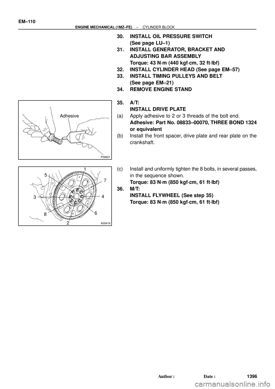
P00601
Adhesive
A05416
1
2 34 5
67
8
EM±110
± ENGINE MECHANICAL (1MZ±FE)CYLINDER BLOCK
1396 Author�: Date�:
30. INSTALL OIL PRESSURE SWITCH
(See page LU±1)
31. INSTALL GENERATOR, BRACKET AND
ADJUSTING BAR ASSEMBLY
Torque: 43 N´m (440 kgf´cm, 32 ft´lbf)
32. INSTALL CYLINDER HEAD (See page EM±57)
33. INSTALL TIMING PULLEYS AND BELT
(See page EM±21)
34. REMOVE ENGINE STAND
35. A/T:
INSTALL DRIVE PLATE
(a) Apply adhesive to 2 or 3 threads of the bolt end.
Adhesive: Part No. 08833±00070, THREE BOND 1324
or equivalent
(b) Install the front spacer, drive plate and rear plate on the
crankshaft.
(c) Install and uniformly tighten the 8 bolts, in several passes,
in the sequence shown.
Torque: 83 N´m (850 kgf´cm, 61 ft´lbf)
36. M/T:
INSTALL FLYWHEEL (See step 35)
Torque: 83 N´m (850 kgf´cm, 61 ft´lbf)