Page 3653 of 4770
IGNITION COIL
1688 Author�: Date�:
REPLACEMENT
1. DISCONNECT THROTTLE BODY FROM INTAKE MAN-
IFOLD (See page SF±32)
2. REMOVE IGN")
IG0DC±01
S05549
Wire
Clamp
S05604
No.1
No.2 IG±6
± IGNITION (5S±FE)IGNITION COIL
1688 Author�: Date�:
REPLACEMENT
1. DISCONNECT THROTTLE BODY FROM INTAKE MAN-
IFOLD (See page SF±32)
2. REMOVE IGNITION COILS AND NO.2 INTAKE MAN-
IFOLD STAY ASSEMBLY
(a) Disconnect the 2 ignition coil connectors.
(b) Disconnect the wire clamp from the manifold stay.
(c) TMC Made:
Remove the 2 nuts, 2 bolts, 2 ignition coils and manifold
stay assembly.
(d) TMMK Made:
Remove the nut, 3 bolts, 2 ignition coils and manifold stay
assembly.
3. REMOVE IGNITION COILS FROM NO.2 INTAKE MAN-
IFOLD STAY
Remove the 2 bolts and ignition coil. Remove the 2 ignition
coils.
4. REINSTALL IGNITION COILS TO NO.2 INTAKE MAN-
IFOLD STAY
Install the ignition coil with the 2 bolts. Install the 2 ignition coils.
Torque: 9.8 N´m (100 kgf´cm, 87 in.´lbf)
NOTICE:
The installation positions of the ignition coils are different
for No.1 and No.2.
5. REINSTALL IGNITION COILS AND NO.2 INTAKE MAN-
IFOLD STAY ASSEMBLY
(a) TMC Made:
Install the 2 ignition coils and manifold stay assembly with
the 2 nuts and 2 bolts.
(b) TMMK Made:
Install the 2 ignition coils and manifold stay assembly with
the nut and 3 bolts.
Torque:
21 N´m (214 kgf´cm, 15 ft´lbf) for 12 mm head
42 N´m (428 kgf´cm, 31 ft´lbf) for 14 mm head
(c) Install the wire clamp to the manifold stay.
(d) Connect the 2 ignition coil connectors.
Page 3656 of 4770
IG0DD±01
± IGNITION (5S±FE)CAMSHAFT POSITION SENSOR
IG±9
1691 Author�: Date�:
REPLACEMENT
1. REMOVE CAMSHAFT POSITION SENSOR
(a) Disconnect the sensor connector.
(b) Remove the bolt and sensor.
2. REINSTALL CAMSHAFT POSITION SENSOR
(a) Install the sensor with the bolt.
Torque: 9.5 N´m (97 kgf´cm, 84 in.´lbf)
(b) Connect the sensor connector.
Page 3657 of 4770
IG047±03
S05284
Engine Moving Control Rod
No.2 RH Engine Mounting Bracket
Generator Drive Belt
RH Front Fender Apron SealPS Pump Drive BeltGround Strap Connector
N´m (kgf´cm, ft´lbf) : Specified torque
64 (650, 47)
64 (650, 47)
52 (530, 38)
IG±10
± IGNITION (5S±FE)CRANKSHAFT POSITION SENSOR
1692 Author�: Date�:
CRANKSHAFT POSITION SENSOR
COMPONENTS
Page 3658 of 4770
S05938
No.2 Timing Belt
Cover
No.1 Timing Belt
Cover
Crankshaft
Pulley
Crankshaft Position Sensor
Connector
Crankshaft Position Sensor Wire ClampWire
Clamp
N´m (kgf´cm, ft´lbf):Specified torqueGenerator * Gasket
Timing Belt Guide Generator Wire
Generator Connector
Wire ClampWire
Clamp
108 (1,100, 80)
* Gasket
* Replace only if damaged
± IGNITION (5S±FE)CRANKSHAFT POSITION SENSOR
IG±11
1693 Author�: Date�:
Page 3663 of 4770
IGNITION SYSTEM
IG±5
1699 Author�: Date�:
(e) Using a 16 mm plug wrench, remove the 6 spark plugs
from")
P13225
16 mm Plug
Wrench
P25746
DENSO PK20TR11 NGK BKR6EKPB11
P20584
IG0152
± IGNITION (1MZ±FE)IGNITION SYSTEM
IG±5
1699 Author�: Date�:
(e) Using a 16 mm plug wrench, remove the 6 spark plugs
from the RH and LH cylinder heads.
(f) Check the spark plug for thread damage and insulator
damage.
If abnormal, replace the spark plug.
Recommended spark plug:
DENSO madePK20TR11
NGK madeBKR6EKPB11
(g) Inspect the electrode gaps.
Maximum electrode gap for used spark plug:
1.3 mm (0.051 in.)
If the gap is greater than maximum, replace the spark plug.
Correct electrode gap for new spark plug:
1.1 mm (0.043 in.)
NOTICE:
If adjusting the gap of a new spark plug, bend only the base
of the ground electrode. Do not touch the tip. Never attempt
to adjust the gap on the used plug.
(h) Clean the spark plugs.
If the electrode has traces of wet carbon, allow it to dry and then
clean with a spark plug cleaner.
Air pressure: Below 588 kPa (6 kgf/cm
2, 85 psi)
Duration: 20 seconds or less
HINT:
If there are traces of oil, remove it with gasoline before using the
spark plug cleaner.
(i) Using a 16 mm plug wrench, install the 6 spark plugs to
the RH and LH cylinder heads.
Torque: 18 N´m (180 kgf´cm, 13 ft´lbf)
(j) Install the ignition coils.
(k) Install the high±tension cords set. (See step 2)
4. INSPECT IGNITION COILS
(a) Disconnect the high±tension cords from the ignition coils.
(b) Disconnect the ignition coil connectors.
Page 3665 of 4770
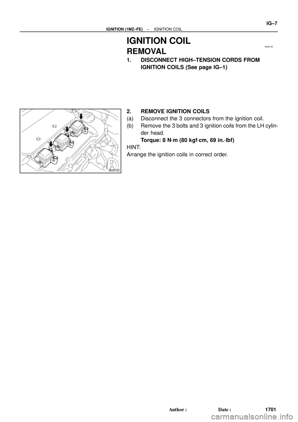
IG02I±03
S04720
± IGNITION (1MZ±FE)IGNITION COIL
IG±7
1701 Author�: Date�:
IGNITION COIL
REMOVAL
1. DISCONNECT HIGH±TENSION CORDS FROM
IGNITION COILS (See page IG±1)
2. REMOVE IGNITION COILS
(a) Disconnect the 3 connectors from the ignition coil.
(b) Remove the 3 bolts and 3 ignition coils from the LH cylin-
der head.
Torque: 8 N´m (80 kgf´cm, 69 in.´lbf)
HINT:
Arrange the ignition coils in correct order.
Page 3667 of 4770
S04589
IG02K±03
± IGNITION (1MZ±FE)CAMSHAFT POSITION SENSOR
IG±9
1703 Author�: Date�:
CAMSHAFT POSITION SENSOR
REMOVAL
REMOVE CAMSHAFT POSITION SENSOR
(a) Disconnect the camshaft position sensor connector.
(b) Remove the 2 bolts and camshaft position sensor.
Torque: 8 N´m (80 kgf´cm, 69 in.´lbf)
Page 3669 of 4770
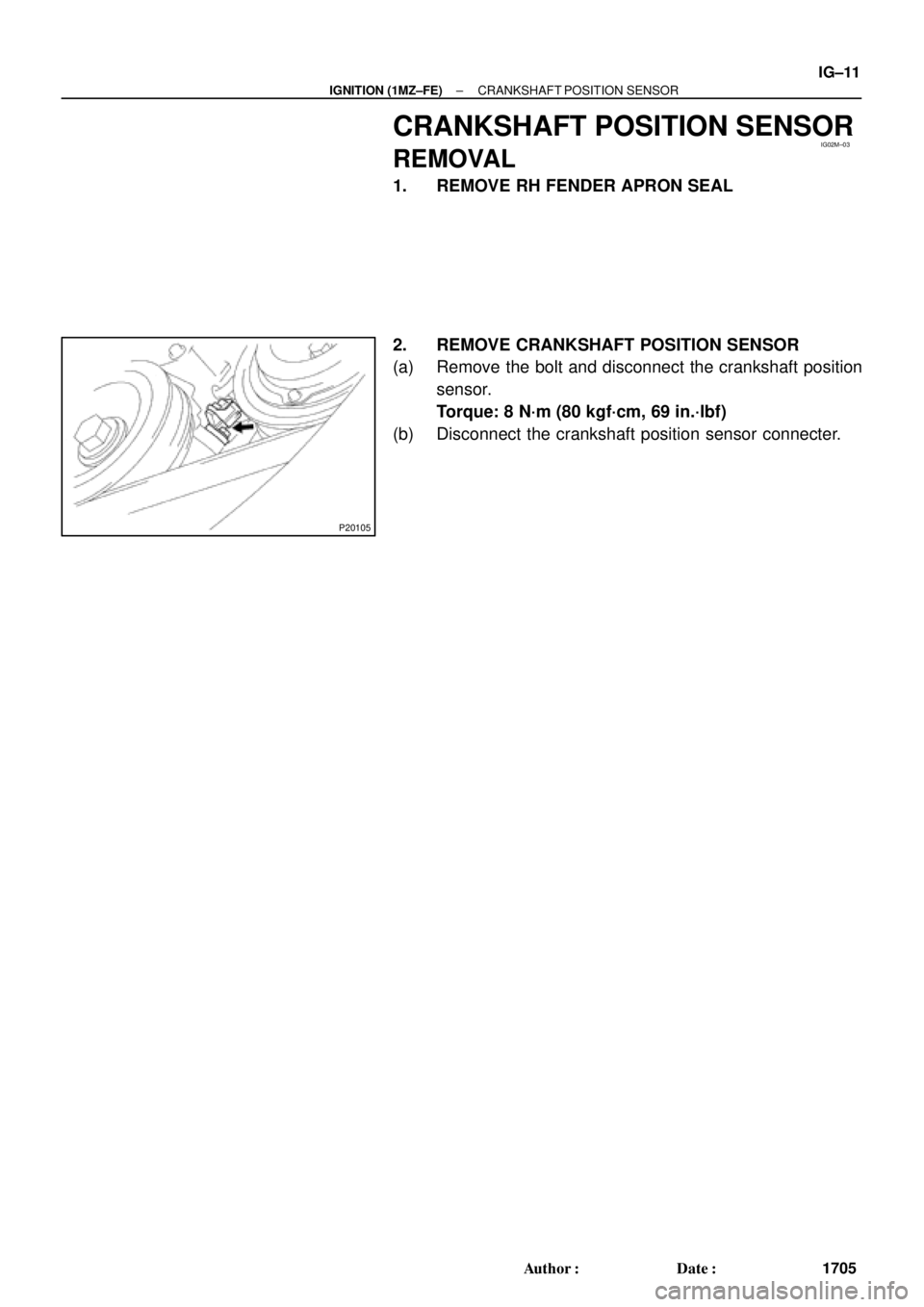
IG02M±03
P20105
± IGNITION (1MZ±FE)CRANKSHAFT POSITION SENSOR
IG±11
1705 Author�: Date�:
CRANKSHAFT POSITION SENSOR
REMOVAL
1. REMOVE RH FENDER APRON SEAL
2. REMOVE CRANKSHAFT POSITION SENSOR
(a) Remove the bolt and disconnect the crankshaft position
sensor.
Torque: 8 N´m (80 kgf´cm, 69 in.´lbf)
(b) Disconnect the crankshaft position sensor connecter.

 : Specified t")
:Specified torqueGene")