Page 3575 of 4770

EM04X±04
A06650
No.2 Cooling Fan Connector
Upper Radiator Support
Radiator Assembly
RH Fender
Apron
Seal
Generator
Drive
Belt
A/C Compressor
ConnectorNo.1 ECT Switch
Wire Connector
Battery
Insulator
Battery
Battery
Tray Generator Drive
Belt Adjusting
Bar Bracket
LH Fender
Apron SealA/T
Oil Cooler
Hose
� Gasket A/C Compressor
43 (440, 32)
25 (250, 18)
�Non±reusable partStay
N´m (kgf´cm, ft´lbf)Bracket Front Exhaust Pipe: Specified torque� Gasket
62 (630, 46)
33 (330, 24)
�
62 (630, 46)
33 (330, 24)
� Gasket
56 (570, 41)
Actuator Cover
EGR Vacuum HoseUpper Radiator
Support
No.1 Cooling
Fan ConnectorHood
Hold±Down
Clamp
Washer
Hose for
Windshield
Air Filter
Air Cleaner Case
� O±Ring Lower Radiator Support
Drain
Plug
Lower Radiator
Support
Air Cleaner
Cap Assembly
Radiator Upper Hose
Cruise Control
Actuator
Cruise Control
Actuator
Connector
Accelerator Cable
PS Pump
Radiator Lower Hose
� PS Pump
Drive Belt
EVAP Hose
MAF Meter
Connector
± ENGINE MECHANICAL (1MZ±FE)ENGINE UNIT
EM±69
1355 Author�: Date�:
ENGINE UNIT
COMPONENTS
Page 3576 of 4770
A06646
RH Drive Shaft
LH Drive Shaft
Tie Rod End
49 (500, 36)
294 (3,000, 217)64 (650, 47)32 (320, 23)
RH Engine
Mounting Stay
Lower Suspension Arm Engine Moving
Control Rod
64 (650, 47)
127 (1,300, 94)
No.2 RH Engine
Mounting Stay (M/T)
No.2 RH Engine
Mounting Bracket
Engine and Transaxle
Assembly
64 (650, 47)
66 (670, 48)
64 (650, 47)
Front Engine
Mounting Insulator
48 (490, 35)
64 (650, 47)
Transaxle
Control Cable
Engine Mounting Absorber
TMC Made 80 (820,59)
TMMK Made
Green Clolr Bolt 66 (670, 48)
Silver Clolr Bolt 44 (450,32)
N´m (kgf´cm, ft´lbf) : Specified torque
� Non±reusable part�
Rear Engine
Mounting
Insulator
EM±70
± ENGINE MECHANICAL (1MZ±FE)ENGINE UNIT
1356 Author�: Date�:
Page 3580 of 4770
P18755
P19478
Engine
Hanger
S04501
S05451
EM±74
± ENGINE MECHANICAL (1MZ±FE)ENGINE UNIT
1360 Author�: Date�:
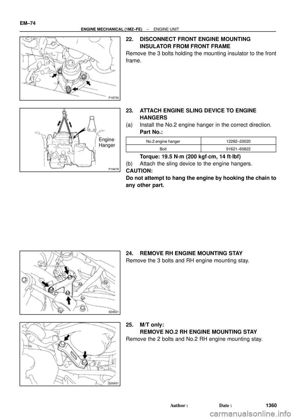
22. DISCONNECT FRONT ENGINE MOUNTING
INSULATOR FROM FRONT FRAME
Remove the 3 bolts holding the mounting insulator to the front
frame.
23. ATTACH ENGINE SLING DEVICE TO ENGINE
HANGERS
(a) Install the No.2 engine hanger in the correct direction.
Part No.:
No.2 engine hanger12282±20020
Bolt91621±60822
Torque: 19.5 N´m (200 kgf´cm, 14 ft´lbf)
(b) Attach the sling device to the engine hangers.
CAUTION:
Do not attempt to hang the engine by hooking the chain to
any other part.
24. REMOVE RH ENGINE MOUNTING STAY
Remove the 3 bolts and RH engine mounting stay.
25. M/T only:
REMOVE NO.2 RH ENGINE MOUNTING STAY
Remove the 2 bolts and No.2 RH engine mounting stay.
Page 3582 of 4770
ENGINE UNIT
1362 Author�: Date�:
INSTALLATION
1. ASSEMBLE ENGINE AND TRANSAXLE
E153 M/T (See page MX±4)
A541E A/T (See")
EM04Z±04
S04992
Lower
S04754
S05451
S04501
EM±76
± ENGINE MECHANICAL (1MZ±FE)ENGINE UNIT
1362 Author�: Date�:
INSTALLATION
1. ASSEMBLE ENGINE AND TRANSAXLE
E153 M/T (See page MX±4)
A541E A/T (See page AX±23)
2. INSTALL REAR ENGINE MOUNTING INSULATOR
Install the mounting insulator with the 4 bolts.
Torque: 64 N´m (650 kgf´cm, 47 ft´lbf)
3. INSTALL FRONT ENGINE MOUNTING INSULATOR
Install the mounting insulator with the 4 bolts.
Torque: 64 N´m (650 kgf´cm, 47 ft´lbf)
4. INSTALL ENGINE AND TRANSAXLE ASSEMBLY IN
VEHICLE
(a) Attach the engine sling device to the engine hangers.
(b) Lower the engine into the engine compartment.
Tilt the transaxle downward, lower the engine and clear
the LH mounting.
NOTICE:
Be careful not to hit the park/neutral position switch.
(c) Keep the engine level, and align RH and LH mountings
with the body bracket.
5. INSTALL NO.2 RH ENGINE MOUNTING BRACKET
AND ENGINE MOVING CONTROL ROD
Install the mounting moving control rod and No.2 RH engine
mounting bracket with the 3 bolts.
Torque: 64 N´m (650 kgf´cm, 47 ft´lbf)
6. M/T only:
INSTALL NO.2 RH ENGINE MOUNTING STAY
Install the No.2 RH engine mounting stay with the 2 bolts.
Torque: 64 N´m (650 kgf´cm, 47 ft´lbf)
7. INSTALL RH ENGINE MOUNTING STAY
Install the RH mounting stay with the 3 bolts.
Torque: 32 N´m (320 kgf´cm, 23 ft´lbf)
Page 3583 of 4770
P18755
A05426
P18752
S05393
M/T
Z18907
A/T
± ENGINE MECHANICAL (1MZ±FE)ENGINE UNIT
EM±77
1363 Author�: Date�:
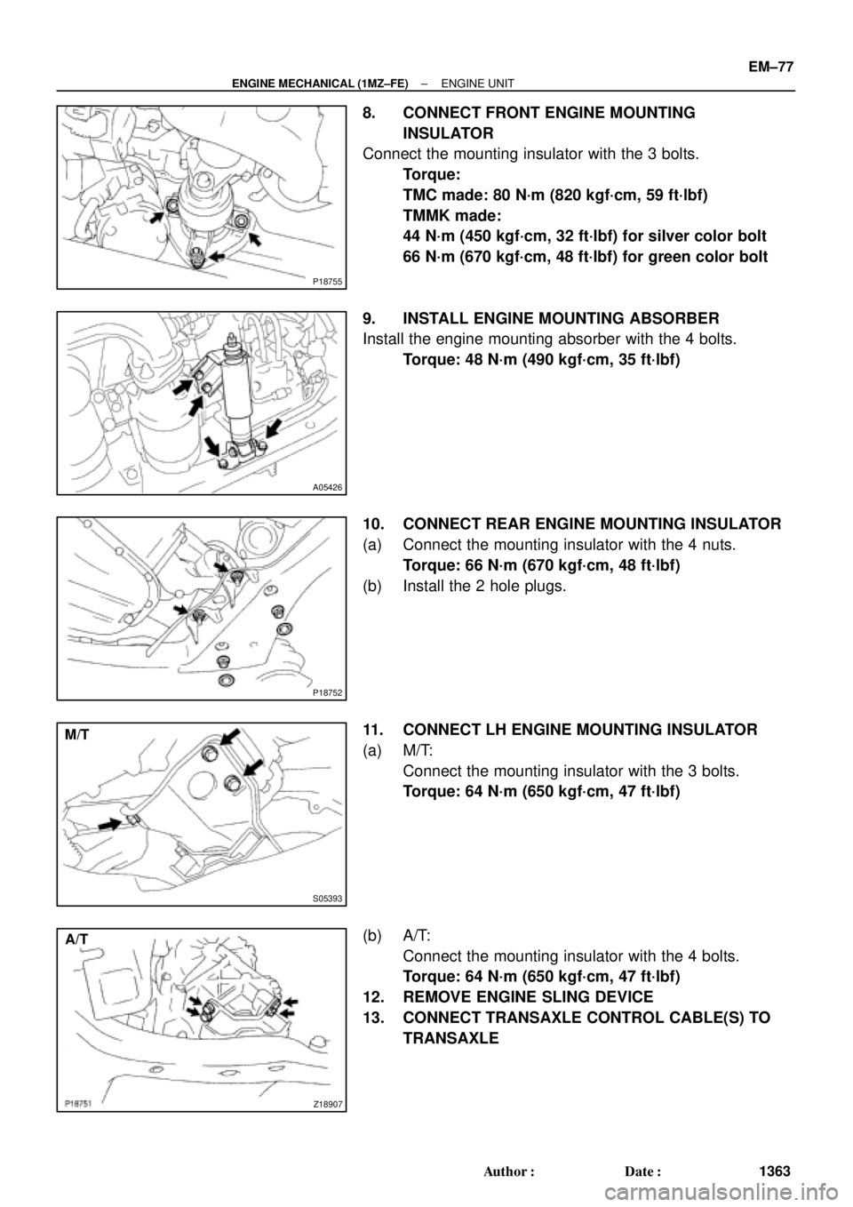
8. CONNECT FRONT ENGINE MOUNTING
INSULATOR
Connect the mounting insulator with the 3 bolts.
Torque:
TMC made: 80 N´m (820 kgf´cm, 59 ft´lbf)
TMMK made:
44 N´m (450 kgf´cm, 32 ft´lbf) for silver color bolt
66 N´m (670 kgf´cm, 48 ft´lbf) for green color bolt
9. INSTALL ENGINE MOUNTING ABSORBER
Install the engine mounting absorber with the 4 bolts.
Torque: 48 N´m (490 kgf´cm, 35 ft´lbf)
10. CONNECT REAR ENGINE MOUNTING INSULATOR
(a) Connect the mounting insulator with the 4 nuts.
Torque: 66 N´m (670 kgf´cm, 48 ft´lbf)
(b) Install the 2 hole plugs.
11. CONNECT LH ENGINE MOUNTING INSULATOR
(a) M/T:
Connect the mounting insulator with the 3 bolts.
Torque: 64 N´m (650 kgf´cm, 47 ft´lbf)
(b) A/T:
Connect the mounting insulator with the 4 bolts.
Torque: 64 N´m (650 kgf´cm, 47 ft´lbf)
12. REMOVE ENGINE SLING DEVICE
13. CONNECT TRANSAXLE CONTROL CABLE(S) TO
TRANSAXLE
Page 3584 of 4770
ENGINE UNIT
1364 Author�: Date�:
14. INSTALL PS PUMP
(a) Install the PS pump with the 2 bolts.
Torque: 43 N´m (440")
P18775
B00881
ConnectorBracket
A
B
A
A
C
S04497
EM±78
± ENGINE MECHANICAL (1MZ±FE)ENGINE UNIT
1364 Author�: Date�:
14. INSTALL PS PUMP
(a) Install the PS pump with the 2 bolts.
Torque: 43 N´m (440 kgf´cm, 31 ft´lbf)
(b) Install the drive belt.
(c) Connect the PS pressure tube with the 2 nuts.
15. INSTALL A/C COMPRESSOR
(a) Install the A/C compressor and drive belt adjusting bar
bracket with the 4 bolts and nut.
Torque:
Bolt A: 25 N´m (250 kgf´cm, 18 ft´lbf)
Bolt B: 18 N´m (185 kgf´cm, 13 ft´lbf)
Nut C: 25 N´m (250 kgf´cm, 18 ft´lbf)
(b) Install the drive belt.
(c) Connect the A/C compressor connector.
16. M/T only:
INSTALL CLUTCH RELEASE CYLINDER AND
ACCUMULATOR
17. M/T only:
INSTALL STARTER (See page ST±19)
18. INSTALL DRIVE SHAFTS (See page SA±32)
19. CONNECT ENGINE WIRE TO CABIN
(a) Push in the engine wire through the cowl panel. Install the
grommet.
(b) Connect the 3 engine ECM connectors.
(c) Connect the 3 cowl wire connectors to the connectors on
the bracket.
(d) Install the No.2 instrument lower panel.
20. CONNECT CONNECTORS, CABLE, CLAMPS AND
HOSES
(a) Connect the igniter connector on the LH fender apron.
(b) Connect the noise filter connector on the LH fender
apron.
(c) Connect the generator connector and wire.
(d) Connect the starter connector and wire.
(e) Connect the 2 ground strap connectors to the RH fender
apron.
Page 3585 of 4770
ENGINE UNIT
EM±79
1365 Author�: Date�:
(f) Connect the 2 ground strap connectors to the LH fender
apron.
(g) Connect the DLC1 to the RH fender apron.
(h) Connect")
S05048
± ENGINE MECHANICAL (1MZ±FE)ENGINE UNIT
EM±79
1365 Author�: Date�:
(f) Connect the 2 ground strap connectors to the LH fender
apron.
(g) Connect the DLC1 to the RH fender apron.
(h) Connect the ground cable to the battery body bracket.
(i) Connect the engine wire protector clamp to the battery
body bracket.
(j) Connect the engine wire clamp to the bracket on the RH
fender apron.
(k) Connect the engine wire clamp to the bracket on the fuel
filter.
(l) Connect the brake booster vacuum hose to the air intake
chamber.
(m) Connect the engine coolant reservoir hose to the water
outlet.
(n) Connect the heater hose to the intake manifold.
(o) Connect the heater hose to the water inlet housing.
(p) Connect the fuel inlet hose to the fuel filter.
CAUTION:
Perform connecting operations of the fuel tube connector
(quick type) after observing the precautions.
(See page SF±6)
(q) Connect the purge hose to the pipe on the emission con-
trol valve set.
(r) Connect the 2 vacuum hoses to the vacuum tank for the
ACIS.
21. INSTALL FRONT EXHAUST PIPE
(a) Temporarily install 3 new gaskets and the front exhaust
pipe with the 2 bolts and 6 nuts.
(b) Tighten the 4 nuts holding the exhaust manifolds to the
front exhaust pipe.
Torque: 62 N´m (630 kgf´cm, 46 ft´lbf)
(c) Tighten the 2 bolts and 2 nuts holding the front exhaust
pipe to the center exhaust pipe.
Torque: 56 N´m (570 kgf´cm, 41 ft´lbf)
(d) Install the bracket with the 2 bolts.
Torque: 33 N´m (330 kgf´cm, 24 ft´lbf)
(e) Install the support stay with the 2 bolts.
Torque: 33 N´m (330 kgf´cm, 24 ft´lbf)
22. INSTALL RADIATOR (See page CO±24)
23. INSTALL CRUISE CONTROL ACTUATOR
24. INSTALL AIR CLEANER CAP ASSEMBLY AND AIR
CLEANER CASE
25. CONNECT ACCELERATOR CABLE
26. INSTALL ENGINE FENDER APRON SEALS
27. INSTALL BATTERY TRAY AND BATTERY
Page 3587 of 4770

No.2 Idler Pulley Bracket
Water Seal Plate
Engine Cool")
EM050±03
A06640
Knock Sensor Connector
Engine Wire Band
Engine WireKnock Sensor
No.2 ECT Switch Connector
Water Inlet Housing
(With Water Inlet)
No.2 Idler Pulley Bracket
Water Seal Plate
Engine Coolant
Drain Union
Oil Filter Union
Oil Filter � Gasket
EGR Cooler
� Gasket
Water Pump
� Crankshaft
Front Oil Seal
Crankshaft
Position Sensor
Connector� Oil Pressure Switch
Oil Pressure Switch
ConnectorA/C Compressor
Housing Bracket
No.1 Oil Pan
x 15 or 17 Oil Pump
� Gasket
� Gasket
Engine Wire
Generator
Drain Plugx 10No.2 Oil Pan Oil Strainer
� Non±reusable part
N´m (kgf´cm, ft´lbf) : Specified torque
Precoated part �
x 8
�
� O±Ring
x 9
9 (90, 78 in.´lbf)
8 (80, 69 in.´lbf)
10mm Head 7.8 (80, 69 in.´lbf)
12mm Head 19.5 (200,14)
39 (400, 29)
28 (290, 21)
14.5 (145, 10)
25 (250, 18)
10mm Head 8 (80, 69 in.´lbf)
12mm Head 19.5 (200,14)
8 (80, 69 in.´lbf)
8 (80, 69 in.´lbf)45 (460, 33)
8 (80, 69 in.´lbf)
or 0 or 0
± ENGINE MECHANICAL (1MZ±FE)CYLINDER BLOCK
EM±81
1367 Author�: Date�:
CYLINDER BLOCK
COMPONENTS

294 (3,000, 217)64 (650, 47)32 (320, 23)
RH Engine
Mounting Stay
Lower Suspension Arm Engine Moving
Control Rod
64 (650, 47)
127 (1,300, 9")