Page 3617 of 4770
EM0YU±01
A06653
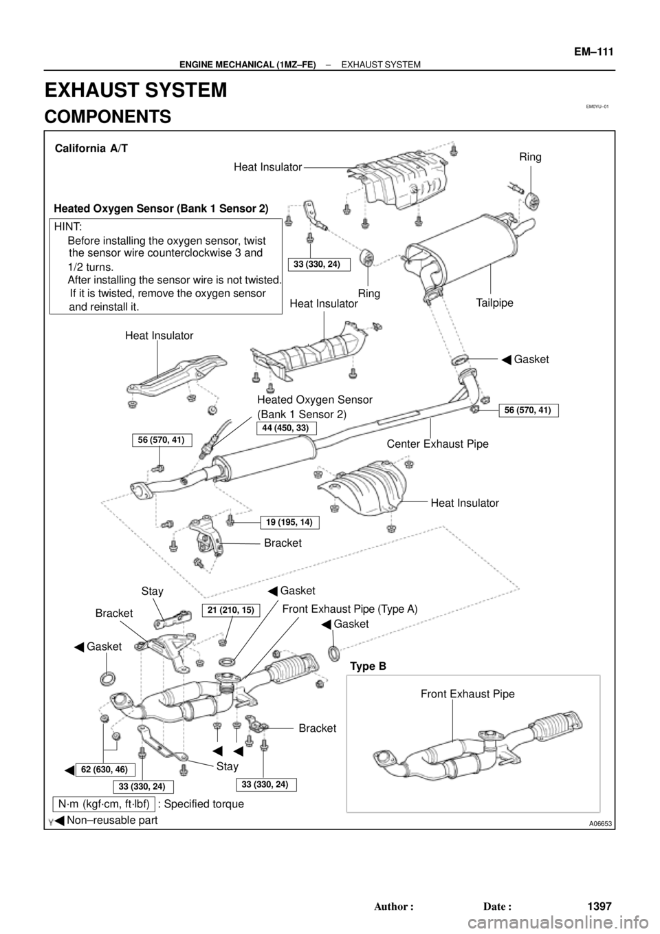
� Gasket
� Non±reusable part
N´m (kgf´cm, ft´lbf) : Specified torque� Gasket
�
�
�BracketFront Exhaust Pipe Bracket
StayHeat Insulator Center Exhaust Pipe� Gasket Heat InsulatorHeat Insulator
Heated Oxygen Sensor
(Bank 1 Sensor 2)TailpipeRing
Ring
33 (330, 24)
Heat Insulator
Heated Oxygen Sensor (Bank 1 Sensor 2)
� Before installing the oxygen sensor, twist
the sensor wire counterclockwise 3 and
1/2 turns.
If it is twisted, remove the oxygen sensor
and reinstall it. � After installing the sensor wire is not twisted. California A/T
Bracket
HINT:
56 (570, 41)
19 (195, 14)
21 (210, 15)
62 (630, 46)
33 (330, 24)33 (330, 24)
56 (570, 41)
Stay
Front Exhaust Pipe (Type A)
Type B
44 (450, 33)
� Gasket
± ENGINE MECHANICAL (1MZ±FE)EXHAUST SYSTEM
EM±111
1397 Author�: Date�:
EXHAUST SYSTEM
COMPONENTS
Page 3618 of 4770
A06652
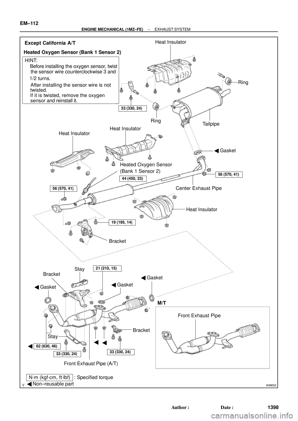
� Gasket
� Non±reusable part
N´m (kgf´cm, ft´lbf) : Specified torque� Gasket
�
�� Gasket
�Bracket
Stay
Front Exhaust Pipe (A/T) BracketBracket
Stay
21 (210, 15)
Heat Insulator Center Exhaust Pipe� Gasket Heat InsulatorHeat Insulator
Heated Oxygen Sensor
(Bank 1 Sensor 2)TailpipeRing
Ring
33 (330, 24)
Heat Insulator
Heated Oxygen Sensor (Bank 1 Sensor 2)
� Before installing the oxygen sensor, twist
the sensor wire counterclockwise 3 and
1/2 turns.
If it is twisted, remove the oxygen
sensor and reinstall it. � After installing the sensor wire is notExcept California A/T
HINT:
56 (570, 41)
19 (195, 14)
62 (630, 46)
33 (330, 24)33 (330, 24)
56 (570, 41)
twisted.
Front Exhaust Pipe
M/T
44 (450, 33)
EM±112
± ENGINE MECHANICAL (1MZ±FE)EXHAUST SYSTEM
1398 Author�: Date�:
Page 3622 of 4770
BO0L2±01
H01975
Door Lock
Cylinder
Outside Handle Front Door Belt Moulding
Door Glass
Door FrameFront Door Upper Moulding
Outside
Rear View
Mirror
Door Glass
Run
5.5 (55, 49 in.´lbf)
5.5 (55, 49 in.´lbf)
5.0 (50, 43 in.´lbf)�
Door Lock
23 (230, 17)
Window Regulator
8.0 (80, 69 in.´lbf)
Door Hinge
X6
7.5 (75, 66 in.´lbf)
Regulator
Motor
X3
31 (310, 22)
26 (260, 19)
8.0 (80, 71 in.´lbf)
30 (300, 22)
31 (310, 22)
Door
Check
Door Hinge
26 (260, 19)
Speaker
Power Window Switch Rear Lower
FrameFront Lower
FrameFront Window Upper
Garnish
Inside Handle Bezel
3.5 (35, 31 in.´lbf)
Driver's Side:
Regulator
Motor
Ptdt
N´m (kgf´cm, ft´lbf) : Specified torqueInside Handle
Door Trim
� Precoated part Door Lock StrikerService Hole Cover BO±12
± BODYFRONT DOOR
2370 Author�: Date�:
2001 CAMRY (RM819U)
FRONT DOOR
COMPONENTS
Page 3623 of 4770

(b)(a)
± BODYFRONT DOOR
BO±13
2371 Author�: Date�:
2001 CAMRY (RM819U)
DISASSEMBLY
1. w/o Power Window:
REMOVE REGULATOR HANDLE
Pull off the snap r")
BO0L3±01
H01738
N20968
N210034 Clips
N20969
(c)
(b)(a)
± BODYFRONT DOOR
BO±13
2371 Author�: Date�:
2001 CAMRY (RM819U)
DISASSEMBLY
1. w/o Power Window:
REMOVE REGULATOR HANDLE
Pull off the snap ring with a shop rag and remove the regulator
handle and plate.
HINT:
At the time of assembly, please refer to the following item.
With the door window fully closed, install the plate and the regu-
lator handle with the snap ring.
2. REMOVE INSIDE HANDLE BEZEL
(a) Using a screwdriver, pry open the screw cover and re-
move the screw.
HINT:
Tape the screwdriver tip before use.
(b) Using a screwdriver, pry out the bezel.
HINT:
Tape the screwdriver tip before use.
3. REMOVE FRONT WINDOW UPPER GARNISH
4. REMOVE DOOR TRIM
(a) Using a screwdriver, remove the screw caps.
HINT:
Tape the screwdriver tip before use.
(b) Remove the 2 clips, 2 screws and 2 bolts.
(c) Insert a screwdriver between the door and door trim to pry
out.
(d) Pull the trim upward to remove it, then remove the power
window switch and disconnect the harness connector.
5. REMOVE THESE PARTS:
(a) Outside rear view mirror
Torque: 5.5 N´m (55 kgf´cm, 49 in.´lbf)
(b) Speaker
6. REMOVE DOOR INSIDE HANDLE
(a) Remove the screw and pull the handle forward.
Torque: 3.5 N´m (35 kgf´cm, 31 in.´lbf)
(b) Remove the link from the clamp.
(c) Remove the inside handle from the ends of the 2 links.
7. REMOVE SERVICE HOLE COVER
Remove the grommet, then remove the service hole cover.
Page 3624 of 4770
N20970
(a)
(b)(b)
N21004
Clip
H01729
: 7 rivets
: clip
: clip
: clip BO±14
± BODYFRONT DOOR
2372 Author�: Date�:
2001 CAMRY (RM819U)
8. REMOVE DOOR GLASS
(a) Open the door glass until the bolt appears in the service
hole.
(b) Remove the 2 bolts and the door glass.
HINT:
Pull the glass upward.
Torque: 8.0 N´m (80 kgf´cm, 71 in.´lbf)
9. REMOVE GLASS RUN
HINT:
Pull the glass run upward.
10. REMOVE FRONT AND REAR SIDE FRAMES
Remove the 2 bolts, 2 nuts and the side frames.
HINT:
Remove the side frames through the service hole.
11. REMOVE FRONT DOOR BELT MOULDING
Pry the rearward end of the front door belt moulding from the
door and remove the moulding.
12. REMOVE FRONT DOOR UPPER MOULDING
(a) Using a drill, cut the flange portion of the 7 rivets.
HINT:
At the time of assembly, please refer to the following item.
Use 7 new rivets.
(b) Pry out the 2 clips and remove the moulding.
Page 3625 of 4770

13. REMOVE WINDOW REGULATOR ASSEMBLY")
H01730
w/ Power Window:
w/o Power Window:
N20971
H01732
w/o Power Door Lock
w/ Power Door Lock
± BODYFRONT DOOR
BO±15
2373 Author�: Date�:
2001 CAMRY (RM819U)
13. REMOVE WINDOW REGULATOR ASSEMBLY
Remove the bolts and window regulator.
Torque: 5.5 N´m (55 kgf´cm, 49 in.´lbf)
HINT:
At the time of reassembly, please refer to the following item.
Apply MP grease to the window regulator rollers.
14. w/ Power Window:
REMOVE MOTOR FROM WINDOW REGULATOR
Remove the 3 screws and motor.
15. REMOVE DOOR LOCK
(a) Remove the 2 clips.
(b) Disconnect the 2 links from the door lock and remove the
links.
(c) Disconnect the 2 links from the outside handle and the
lock cylinder.
(d) Remove the 3 screws and door lock.
HINT:
At the time of reassembly, please refer to the following item.
Apply adhesive to 3 screws.
Part No. 08833±00070, THREE BOND 1324 or equiva-
lent
Torque: 5.0 N´m (50 kgf´cm, 43 in.´lbf)
(e) w/ Power Door Lock:
Disconnect the connector.
(f) Remove the door lock through the service hole.
HINT:
At the time of reassembly, please refer to the following item.
Apply MP grease to the sliding surface of the door lock.
16. REMOVE OUTSIDE HANDLE
Torque: 7.0 N´m (70 kgf´cm, 61 in.´lbf)
Page 3626 of 4770
BO0L4±01
N20966SST
N20967
BO2556
BO±16
± BODYFRONT DOOR
2374 Author�: Date�:
2001 CAMRY (RM819U)
ADJUSTMENT
1. ADJUST DOOR IN FORWARD/REARWARD AND VER-
TICAL DIRECTIONS
Using SST, adjust the door by loosening the body side hinge
bolts.
SST 09812±00020
Torque: 31 N´m (310 kgf´cm, 22 ft´lbf)
2. ADJUST DOOR IN LEFT/RIGHT AND VERTICAL
DIRECTIONS
To adjust, loosen the door side hinge.
HINT:
Substitute the bolt and washer for the centering bolt.
Torque: 26 N´m (260 kgf´cm, 19 ft´lbf)
3. ADJUST DOOR LOCK STRIKER
(a) Check that door fits and the door lock linkages are ad-
justed correctly.
(b) Loosen the striker mounting screws to adjust.
(c) Using a plastic hammer, tap the striker to adjust it.
Torque: 23 N´m (230 kgf´cm, 17 ft´lbf)
Page 3627 of 4770
BO0L6±01
H01733
Door LockRear Door Upper
Moulding
Door Belt Moulding
Door Glass
Outside handle
Door Glass Run
Door Lock
Door Lock Striker
Rear Side Frame
Rear Door WeatherstripWindow Regulator
Inside Handle BezelInside HandleWindow
Regulator
Motor Child Protector
Lock Lever Cover
Snap Ring
Regulator
Handle Plate Door Trim Service Hole Cover Power Window
Switch Cover Door HingeDoor Hinge
Door Check w/o Power Door
Lock:
w/o Power Window:
: Specified torque
N´m (kgf´cm, ft´lbf)
3.5 (35, 31 in.´lbf)
5.5 (55, 49 in.´lbf)
5.5 (55, 49 in.´lbf)
23 (230, 17)
7.0 (70, 61 in.´lbf)
Door Lock Control Link
Door Lock Remote
Control Link
5.0 (50, 43 in.´lbf)
8.0 (80, 71 in.´lbf)
26 (260, 19)
8.0 (80, 71 in.´lbf)
30 (300, 22)
26 (260, 19)
BO±18
± BODYREAR DOOR
2376 Author�: Date�:
2001 CAMRY (RM819U)
REAR DOOR
COMPONENTS

5.5 (55, 49 in")