Page 3628 of 4770

DISASSEMBLY
1. w/o Power Window:
REMOVE REGULATOR HANDLE
Pull off the snap ring with a s")
H01738
BO0L8±01
N20968
N210076 Clips
N20969
± BODYREAR DOOR
BO±19
2377 Author�: Date�:
2001 CAMRY (RM819U)
DISASSEMBLY
1. w/o Power Window:
REMOVE REGULATOR HANDLE
Pull off the snap ring with a shop rag and remove the regulator
handle and plate.
HINT:
At the time of reassembly, please refer to the following item.
With the door window fully closed, install the plate and the regu-
lator handle with the snap ring.
2. w/ Power Window:
REMOVE POWER WINDOW SWITCH
Using a screwdriver, pry out the switch, then disconnect the
connector.
HINT:
Tape the screwdriver tip before use.
3. REMOVE INSIDE HANDLE BEZEL
(a) Using a screwdriver, pry open the screw cover and re-
move the screw.
HINT:
Tape the screwdriver tip before use.
(b) Using a screwdriver, pry out the bezel.
HINT:
Tape the screwdriver tip before using. Use the screwdriver to re-
lease the bezel from the top and bottom protrusions on the han-
dle assembly as shown.
4. REMOVE DOOR TRIM
HINT:
Tape a screwdriver tip before use.
(a) Using the screwdriver, remove the 2 screw caps.
(b) Remove the inside cover.
(c) Remove the 2 screws and clip.
(d) Insert the screwdriver between the door and door trim to
pry out.
(e) Pull the trim upward to remove it, then disconnect the con-
nector.
5. REMOVE DOOR INSIDE HANDLE
(a) Remove the screw and pull the handle forward.
Torque: 3.5 N´m (35 kgf´cm, 31 in.´lbf)
(b) Remove the link from the clamp.
(c) Remove the inside handle from the ends of the 2 links.
6. REMOVE SERVICE HOLE COVER
Remove the grommet, then remove the service hole cover.
Page 3629 of 4770
N20974
(b)(b)
(a)
N21008
Clip
H01743
: 7 rivets
: clips
: clips
: clips BO±20
± BODYREAR DOOR
2378 Author�: Date�:
2001 CAMRY (RM819U)
7. REMOVE DOOR GLASS AND RUN
(a) Remove the bolt and nut holding the rear side frame to the
door.
(b) Remove the 2 bolts holding the door glass to the window
regulator.
Torque: 8.0 N´m (80 kgf´cm, 71 in.´lbf)
(c) Remove the rear side frame and the rear section of the
door glass run.
Torque: 5.5 N´m (55 kgf´cm, 49 in.´lbf)
HINT:
Pull the door glass run upward.
(d) Remove the door glass.
(e) Remove the entire door glass run.
HINT:
Pull the door glass run upward.
8. REMOVE REAR DOOR BELT MOULDING
Pry the rearward end of the rear door belt moulding from the
door and remove the moulding.
9. REMOVE REAR DOOR UPPER MOULDING
(a) Using a drill, cut the flange portion of the 5 rivets.
HINT:
Use 5 new rivets.
(b) Insert a screwdriver between the door and the rear door
upper moulding and pry it off.
Page 3630 of 4770

(b)(a )
H01746
w/o Power Door Lock
w/ Power Door Lock
± BODYREAR DOOR
BO±21
2379 Author�: Date�:
2001 CAMRY (RM819U)
10. REMOVE WINDOW REGULATO")
H01744
w/ Power Window:
w/o Power Window:
N20975
(b)
(b)(a )
H01746
w/o Power Door Lock
w/ Power Door Lock
± BODYREAR DOOR
BO±21
2379 Author�: Date�:
2001 CAMRY (RM819U)
10. REMOVE WINDOW REGULATOR ASSEMBLY
Remove the bolts and window regulator assembly.
Torque: 5.5 N´m (55 kgf´cm,49 in.´lbf)
HINT:
At the time of reassembly, please refer to the following item.
Apply MP grease to the window regulator rollers.
11. w/ Power Window:
REMOVE MOTOR FROM WINDOW REGULATOR
Remove the 3 screws and motor.
12. REMOVE REAR DOOR LOCK CHILD PROTECTION
COVER
Using a screwdriver, pry out the cover.
HINT:
Tape the screwdriver tip before use.
13. REMOVE DOOR LOCK
(a) Remove the clip.
(b) Disconnect the 2 links from the door lock and remove the
2 links.
(c) Disconnect the link from the outside handle.
(d) Remove the 3 screws.
Torque: 5.0 N´m (50 kgf´cm, 43 in.´lbf)
HINT:
At the time of reassembly, please refer to the following item.
Apply adhesive to the 3 screws.
Part No. 08833±00070, THREE BOND 1324 or equiva-
lent
(e) w/ Power Door Lock:
Disconnect the connector.
(f) Remove the door lock through the service hole.
HINT:
At the time of reassembly, please refer to the following item.
Apply MP grease to the sliding surface of the door lock.
14. REMOVE OUTSIDE HANDLE
Torque: 7.0 N´m (70 kgf´cm, 61 in.´lbf)
Page 3631 of 4770

ADJUSTMENT
1. ADJUST DOOR IN FORWARD/REARWARD AND VER-
TICAL DIRECTION
(a) Remo")
BO0L7±01
N21006
3 Clips
2 Clips
N20972
N20973
BO2556
BO±22
± BODYREAR DOOR
2380 Author�: Date�:
2001 CAMRY (RM819U)
ADJUSTMENT
1. ADJUST DOOR IN FORWARD/REARWARD AND VER-
TICAL DIRECTION
(a) Remove the front part of the rear seat side garnish.
(b) Remove the rear part of the front door inside scuff plate.
(c) Remove the center pillar lower garnish.
HINT:
Pull both sides of the top and bottom part of the garnish out-
ward, then pull out to remove the garnish.
(d) Loosen the body side hinge nuts to adjust.
Torque: 26 N´m (260 kgf´cm, 19 ft´lbf)
(e) Install center pillar lower garnish.
(f) Install front door inside scuff plate.
(g) Install rear seat side garnish.
2. ADJUST DOOR IN LEFT/RIGHT AND VERTICAL
DIRECTIONS
Loosen the door side hinge bolts to adjust.
HINT:
Substitute a bolt with washer for the centering bolt.
Torque: 26 N´m (260 kgf´cm, 19 ft´lbf)
3. ADJUST DOOR LOCK STRIKER
(a) Check that the door fit and door lock linkages are adjusted
correctly.
(b) Loosen the striker mounting screws to adjust.
Torque: 23 N´m (230 kgf´cm, 17 ft´lbf)
(c) Using a plastic hammer, tap the striker to adjust it.
Page 3632 of 4770

BO0MB±01
N20950
Instrument Panel ReinforcementNN
DD
No.2 Instrumental Panel Bracket
No.1 Instrumental Panel Bracket
No.2 Instrumental Panel Brace
QQH N
N
N
N
GG
NG
NOB
NN
Instrument Panel Brace Mount
No.1 Instrument
Panel BraceFront Pillar Garnish
Front Pillar
GarnishFront
Passenger
Airbag
Assembly
20 (200, 14)
No.2 Side Defroster Nozzle
Cowl Side Trim
Front Door Openin
g
Cover
Instrument Panel
C
Remote Control
Mirror Hole Base
Upper Column
CoverHazard Warning
Switch
Lower Finish
PlateGlove Compartment
Door Finish PlateFront Door
Inside Scuff Plate
FFF
FJ
Glove
Compartment
No.2 Lower
Panel A
A
Cluster Finish
Panel
Lower Column
Cover
Front Door
Opening
Cover
Cowl Side
TrimD
DD
D
D
F
AA
Lower Panel
InsertCoin
BoxCombination SwitchCombination
MeterRadio Assembly
Center Cluster
Finish Panel
A/C
Control Assembly
35 (360, 26)
Steering
Wheel
Pad Steering Wheel No.1 Lower
Panel
Front Door
Inside Scuff PlateFront Console
Box
Center Console
Upper PanelF
F
B
B
Rear Console
Box
N´m (kgf´cm, ft´lbf) : Specified torque BO±72
± BODYINSTRUMENT PANEL
2430 Author�: Date�:
2001 CAMRY (RM819U)
INSTRUMENT PANEL
COMPONENTS
Page 3637 of 4770

19. REMOVE FRONT PASSENGER AIRBAG ASSEMBLY
(See page RS±28)
Remove the 2 bolts, 4 nuts and the fr")
W03509
N20991
N20992
N20993
± BODYINSTRUMENT PANEL
BO±77
2435 Author�: Date�:
2001 CAMRY (RM819U)
19. REMOVE FRONT PASSENGER AIRBAG ASSEMBLY
(See page RS±28)
Remove the 2 bolts, 4 nuts and the front passenger airbag as-
sembly.
Torque:
Bolt: 20 N´m (200 kgf´cm, 14 ft´lbf)
CAUTION:
�Store the front passenger airbag door facing upward
(never downward).
�Never disassemble the front passenger airbag as-
sembly.
NOTICE:
The 2 bolts to the instrument panel have been anti±rust
treated. After removing the front passenger airbag assem-
bly, always replace the bolts and nuts with new ones.
20. REMOVE No.1 AND No.2 INSTRUMENT PANEL
BRACKETS
Remove the 4 bolts and the No.1 and No.2 panel brackets.
21. REMOVE NO.2 SIDE DEFROSTER NOZZLE
22. REMOVE INSTRUMENT PANEL ASSEMBLY
(a) Disconnect the connectors from the LH and RH connector
holders.
(b) Remove the bolts holding the ground wire to the body.
(c) Remove the connector holder from the body.
(d) Disconnect the connectors.
(e) Remove the bolt holding the ground wire to the No.2
instrument panel brace.
Page 3650 of 4770
IGNITION SYSTEM
IG±3
1685 Author�: Date�:
(c) Using a 16 mm plug wrench, remove the 4 spark plugs.
(d) Visually check the sp")
S05308
16 mm Plug
Wrench
P20584
IG0152
B06373
Ohmmeter
± IGNITION (5S±FE)IGNITION SYSTEM
IG±3
1685 Author�: Date�:
(c) Using a 16 mm plug wrench, remove the 4 spark plugs.
(d) Visually check the spark plug for thread damage and insu-
lator damage.
If abnormal, replace the spark plug.
Recommended spark plug:
DENSO madePK20TR11
NGK madeBKR6EKPB11
(e) Inspect the electrode gaps.
Maximum electrode gap for used spark plug:
1.3 mm (0.051 in.)
If the gap is greater than maximum, replace the spark plug.
Correct electrode gap for new spark plug:
1.1 mm (0.043 in.)
NOTICE:
If adjusting the gap of a new spark plug, bend only the base
of the ground electrode. Do not touch the tip. Never attempt
to adjust the gap on the used plug.
(f) Clean the spark plugs.
If the electrode has traces of wet carbon, allow it to dry and then
clean with a spark plug cleaner.
Air pressure: Below 588 kPa (6 kgf/cm
2, 85 psi)
Duration: 20 seconds or less
HINT:
If there are traces of oil, remove it with gasoline before using the
spark plug cleaner.
(g) Using a 16 mm plug wrench, install the 4 spark plugs.
Torque: 18 N´m (180 kgf´cm, 13 ft´lbf)
(h) Reconnect the high±tension cords from the spark plugs.
4. INSPECT IGNITION COILS WITH IGNITERS
(a) Disconnect the high±tension cords from the ignition coils.
(b) Inspect the secondary coil resistance.
Using an ohmmeter, measure the resistance between the
high±tension terminals.
Secondary coil resistance:
Cold9.7 ± 16.7 kW
Hot12.4 ± 19.6 kW
Page 3652 of 4770
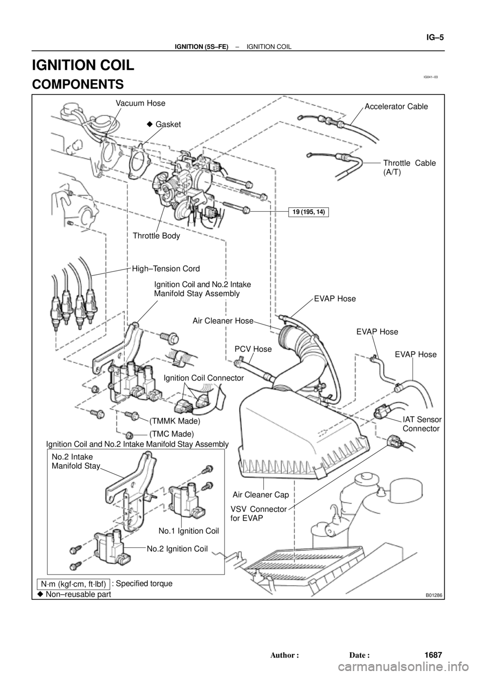
IG041±03
B01286
Vacuum Hose
� GasketAccelerator Cable
Throttle Cable
(A/T)
Throttle Body
High±Tension Cord
Ignition Coil and No.2 Intake
Manifold Stay Assembly
EVAP Hose
Air Cleaner Hose
IAT Sensor
Connector PCV Hose
VSV Connector
for EVAP
No.2 Ignition CoilNo.1 Ignition Coil No.2 Intake
Manifold Stay
N´m (kgf´cm, ft´lbf): Specified torque
� Non±reusable part
19 (195, 14)
EVAP Hose
EVAP Hose
Ignition Coil Connector
Air Cleaner Cap Ignition Coil and No.2 Intake Manifold Stay Assembly
(TMMK Made)
(TMC Made)
± IGNITION (5S±FE)IGNITION COIL
IG±5
1687 Author�: Date�:
IGNITION COIL
COMPONENTS