Page 3563 of 4770
CYLINDER HEAD
EM±57
1343 Author�: Date�:
INSTALLATION
1. PLACE C")
EM0YR±01
P12393
P12736
12 Pointed Head Bolt
Front7246
5318
7246 5318
P25742
Painted Mark
90°
Front90°
± ENGINE MECHANICAL (1MZ±FE)CYLINDER HEAD
EM±57
1343 Author�: Date�:
INSTALLATION
1. PLACE CYLINDER HEAD ON CYLINDER BLOCK
(a) Place 2 new cylinder head gaskets in position on the cylin-
der block.
NOTICE:
Be careful of the installation direction.
(b) Place the 2 cylinder heads in position on the cylinder head
gaskets.
2. INSTALL 12 POINTED HEAD CYLINDER HEAD BOLTS
HINT:
�The cylinder head bolts are tightened in 2 progressive
steps (steps (c) and (e)).
�If any bolt is broken or deformed, replace it.
(a) Apply a light coat of engine oil on the threads and under
the heads of the cylinder head bolts.
(b) Install the plate washer to the cylinder head bolt.
(c) Install and uniformly tighten the cylinder head bolts on
each cylinder head, in several passes, in the sequence
shown, then repeat for the other side, as shown.
Torque: 54 N´m (550 kgf´cm, 40 ft´lbf)
If any of the cylinder head bolts does not meet the torque speci-
fication, replace the cylinder head bolt.
(d) Mark the front of the cylinder head bolt head with paint.
(e) Retighten the cylinder head bolts by 90° in the numerical
order shown.
(f) Check that the painted mark is now at a 90° angle to the
front.
Page 3564 of 4770
P12814
Recessed Head Bolt
8 mm Hexagon Wrench
Front
P12595
Z09320
(3)
(2)
(1)
P12590
EM±58
± ENGINE MECHANICAL (1MZ±FE)CYLINDER HEAD
1344 Author�: Date�:
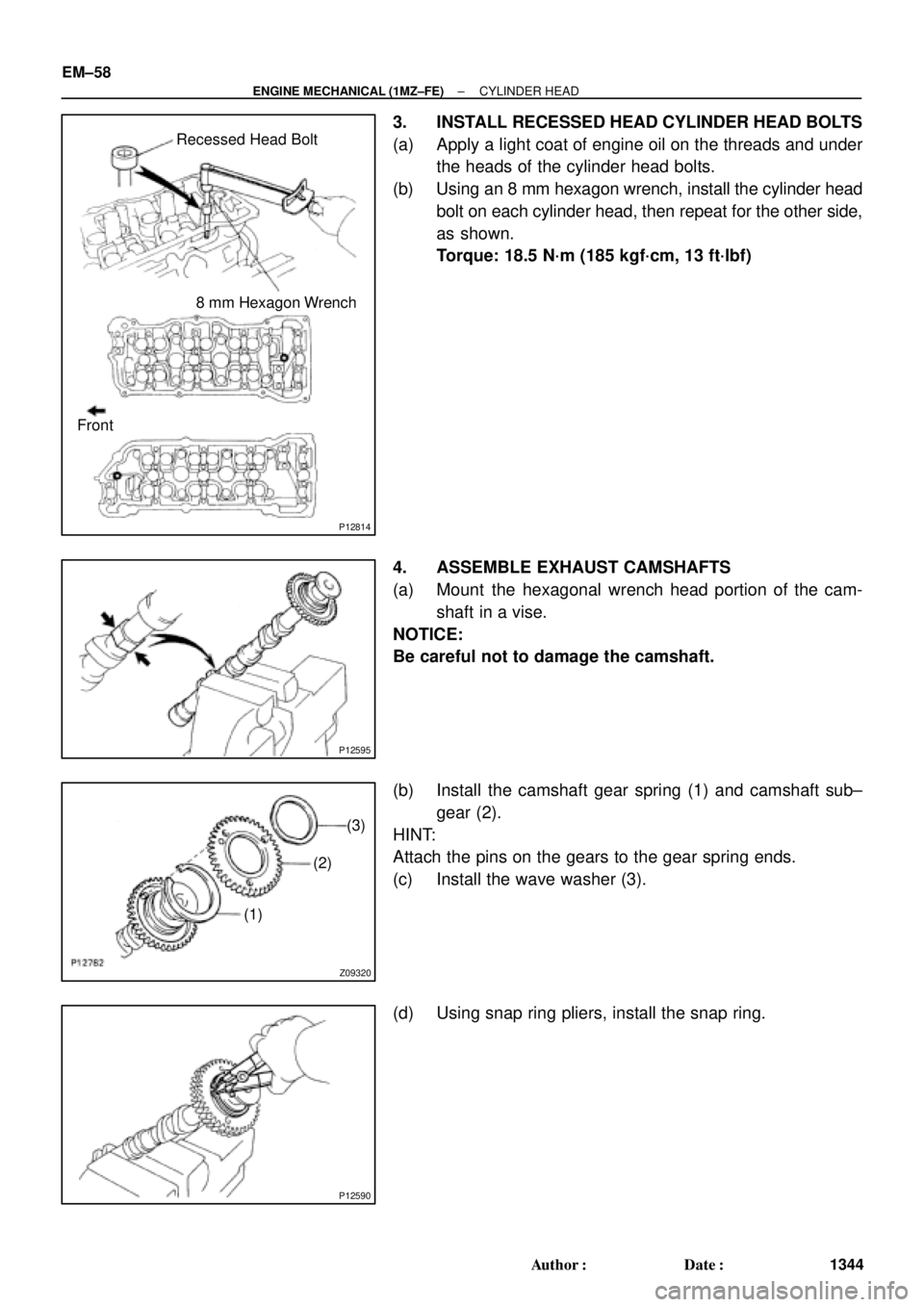
3. INSTALL RECESSED HEAD CYLINDER HEAD BOLTS
(a) Apply a light coat of engine oil on the threads and under
the heads of the cylinder head bolts.
(b) Using an 8 mm hexagon wrench, install the cylinder head
bolt on each cylinder head, then repeat for the other side,
as shown.
Torque: 18.5 N´m (185 kgf´cm, 13 ft´lbf)
4. ASSEMBLE EXHAUST CAMSHAFTS
(a) Mount the hexagonal wrench head portion of the cam-
shaft in a vise.
NOTICE:
Be careful not to damage the camshaft.
(b) Install the camshaft gear spring (1) and camshaft sub±
gear (2).
HINT:
Attach the pins on the gears to the gear spring ends.
(c) Install the wave washer (3).
(d) Using snap ring pliers, install the snap ring.
Page 3566 of 4770
CYLINDER HEAD
1346 Author�: Date�:
(b) Install th")
P12890
Exhaust
P12887
Exhaust
8
76
5
4
32
19 10
P12875
Intake
Align
P12798
Intake
P25422
Intake
8 76 5
4 32 19
10
EM±60
± ENGINE MECHANICAL (1MZ±FE)CYLINDER HEAD
1346 Author�: Date�:
(b) Install the 5 bearing caps in their proper locations.
(c) Apply a light coat of engine oil on the threads and under
the heads of the bearing cap bolts.
(d) Install and uniformly tighten the 10 bearing cap bolts, in
several passes, in the sequence shown.
Torque: 16 N´m (160 kgf´cm, 12 ft´lbf)
(e) Install the Intake camshaft.
(1) Apply new engine oil to the thrust portion and jour-
nal of the camshaft.
(2) Align the timing marks (2 dot marks) of the camshaft
drive and driven gears.
(3) Place the intake camshaft on the cylinder head.
(4) Install the 5 bearing caps in their proper locations.
(5) Apply a light coat of engine oil on the threads and
under the heads of the bearing cap bolts.
(6) Install and uniformly tighten the 10 bearing cap
bolts, in several passes, in the sequence shown.
Torque: 16 N´m (160 kgf´cm, 12 ft´lbf)
Page 3568 of 4770
CYLINDER HEAD
1348 Author�: Date�:
(7) Install t")
P12962
Exhaust
P25421
Exhaust
86 5
4 32 19
10
7
P12874
Intake
Align
P12961
Intake
P12959
Intake
6
5
4
32
19 10
7 8 EM±62
± ENGINE MECHANICAL (1MZ±FE)CYLINDER HEAD
1348 Author�: Date�:
(7) Install the 5 bearing caps in their proper locations.
(8) Apply a light coat of engine oil on the threads and
under the heads of the bearing cap bolts.
(9) Install and uniformly tighten the 10 bearing cap
bolts, in several passes, in the sequence shown.
Torque: 16 N´m (160 kgf´cm, 12 ft´lbf)
(b) Install the intake camshaft.
(1) Apply new engine oil to the thrust portion and jour-
nal of the camshaft.
(2) Align the timing marks (1 dot mark) of the camshaft
drive and driven gears.
(3) Place the intake camshaft on the cylinder head.
(4) Install the 5 bearing caps in their proper locations.
(5) Apply a light coat of engine oil on the threads and
under the heads of bearing cap bolts.
(6) Install and uniformly tighten the 10 bearing cap
bolts, in several passes, in the sequence shown.
Torque: 16 N´m (160 kgf´cm, 12 ft´lbf)
Page 3570 of 4770
CYLINDER HEAD
1350 Author")
P12812
: Seal Packing
Front
RH Side
LH Side
A06649
Manifold
StayM/T and California A/T
Manifold
Stay
Except M/T and California A/T
P18773
EM±64
± ENGINE MECHANICAL (1MZ±FE)CYLINDER HEAD
1350 Author�: Date�:
9. INSTALL CYLINDER HEAD COVERS
(a) Apply seal packing to the cylinder heads as shown in the
illustration.
Seal packing: Part No. 08826±00080 or equivalent
(b) Install the gasket to the cylinder head cover.
(c) Install the cylinder head cover with the 8 bolts. Uniformly
tighten the bolts in several passes. Install the 2 cylinder
head covers.
Torque: 8 N´m (80 kgf´cm, 69 in.´lbf)
10. INSTALL RH EXHAUST MANIFOLD
(a) Install a new gasket and the exhaust manifold with the 6
nuts. Uniformly tighten the nuts in several passes.
Torque: 49 N´m (500 kgf´cm, 36 ft´lbf)
(b) Install the exhaust manifold stay with the bolt and nut. Al-
ternately tighten the bolt and nut.
Torque:
M/T and California A/T
34 N´m (350 kgf´cm, 25 ft´lbf)
Except M/T and California A/T:
20 N´m (200 kgf´cm, 15 ft´lbf)
(c) California:
Connect the A/F sensor connector.
(d) Except California:
Connect the heated oxygen sensor (bank 1 sensor 1)
connector.
11. INSTALL NO.1 EGR PIPE
Install 2 new gaskets and the EGR pipe with the 4 nuts.
Torque: 12 N´m (120 kgf´cm, 9 ft´lbf)
12. INSTALL PS PUMP BRACKET
Torque: 43 N´m (440 kgf´cm, 32 ft´lbf)
Page 3571 of 4770
Except California A/T
S04789
Ground
Strap
Inlet PipeRear
Plate
± ENGINE MECHANICAL (1MZ±FE)CYLINDER HEAD
EM±65
1351")
P12710
New O±Ring
A01522
Manifold
Stay California A/T
Manifold Stay
(Except M/T)Except California A/T
S04789
Ground
Strap
Inlet PipeRear
Plate
± ENGINE MECHANICAL (1MZ±FE)CYLINDER HEAD
EM±65
1351 Author�: Date�:
13. INSTALL OIL DIPSTICK AND GUIDE
(a) Install a new O±ring to the dipstick guide.
(b) Apply soapy water to the O±ring.
(c) Push in the dipstick guide end into the guide hole of the
No.1 oil pan.
(d) Install the dipstick guide with the bolt.
Torque: 8 N´m (80 kgf´cm, 69 in.´lbf)
(e) Install the dipstick.
14. INSTALL CAMSHAFT POSITION SENSOR
15. INSTALL LH EXHAUST MANIFOLD
(a) Install a new gasket and the exhaust manifold with the 6
nuts. Uniformly tighten the nuts in several passes.
Torque: 49 N´m (500 kgf´cm, 36 ft´lbf)
(b) Except M/T:
Install the exhaust manifold stay with the bolt and nut. Al-
ternately tighten the bolt and nut.
Torque:
California A/T:
34 N´m (350 kgf´cm, 25 ft´lbf)
Except California A/T:
20 N´m (200 kgf´cm, 15 ft´lbf)
(c) California:
Connect the A/F sensor connector.
(d) Except California:
Connect the heated oxygen sensor (bank 2 sensor 1)
connector.
16. INSTALL WATER INLET PIPE
(a) Install a new O±ring to the water inlet pipe.
(b) Apply soapy water to the O±ring.
(c) Connect the water inlet pipe to the water inlet.
(d) Install the bolt holding the water inlet pipe to the cylinder
head.
Torque: 19.5 N´m (200 kgf´cm, 14 ft´lbf)
17. INSTALL CYLINDER HEAD REAR PLATE
Torque: 8 N´m (80 kgf´cm, 69 in.´lbf)
18. INSTALL ENGINE WIRE PROTECTOR
19. INSTALL NO.3 TIMING BELT COVER
(a) Check that the timing belt cover gaskets have no cracks
or peeling, etc.
If the gaskets have cracks or peeling etc., replace them using
these steps:
�Using a screwdriver and gasket scraper, remove all
the old gasket material.
�Thoroughly clean all components to remove all the
loose material.
Page 3572 of 4770

L = 180 mm (7.09 in.)L = 72 mm (2.83 in.)
L = 335 mm (13.19 in.)L = 180 mm
(7.09 in.)
L = Length Join
LineJoin
Line
Z14262New Gasket
A01808
8
6
5
4
3
2
1
9
10
7
11
EM")
A05194
L = 133 mm (5.24 in.)
L = 180 mm (7.09 in.)L = 72 mm (2.83 in.)
L = 335 mm (13.19 in.)L = 180 mm
(7.09 in.)
L = Length Join
LineJoin
Line
Z14262New Gasket
A01808
8
6
5
4
3
2
1
9
10
7
11
EM±66
± ENGINE MECHANICAL (1MZ±FE)CYLINDER HEAD
1352 Author�: Date�: �
Remove the backing paper from a new gasket and
install the gasket evenly to the part of the timing belt
cover shaded black in the illustration.
NOTICE:
When joining 2 gaskets, do not leave a gap between them.
Cut off any excess gasket.
�After installing the gasket, press down on it so that
the adhesive firmly sticks to the timing belt cover.
(b) Install the timing belt cover with the 6 bolts.
Torque: 8.5 N´m (85 kgf´cm, 74 in.´lbf)
(c) Install the 3 engine wire clamps to the timing belt cover.
20. INSTALL NO.2 IDLER PULLEY (See page EM±21)
21. INSTALL CAMSHAFT TIMING PULLEYS
(See page EM±21)
22. INSTALL TIMING BELT (See page EM±21)
23. INSTALL SPARK PLUGS
24. INSTALL IGNITION COILS
25. INSTALL PS PUMP DRIVE BELT
26. INSTALL GENERATOR DRIVE BELT
(See page SR±28)
27. INSTALL WATER OUTLET
(a) Install 2 new gaskets.
(b) Connect the water outlet to the bypass hose.
(c) Install the water outlet with the 2 bolts, 2 nuts and 2 plate
washers. Alternately tighten the bolts and nuts.
Torque: 15 N´m (150 kgf´cm, 11 ft´lbf)
NOTICE:
Do not scratch the seal surface of the water outlet with the
stud bolt.
(d) Connect the ECT sender gauge connector.
(e) Connect the ECT sensor connector.
(f) Connect the ground strap (connector).
(g) Connect the radiator hose.
(h) Connect the engine coolant reservoir hose.
28. INSTALL INTAKE MANIFOLD ASSEMBLY
(a) Install the intake manifold, delivery pipe and injectors as-
sembly with the 9 bolts, 2 plate washers and 2 nuts. Uni-
formly tighten the bolts and nuts, in several passes, in the
sequence shown.
Torque: 15 N´m (150 kgf´cm, 11 ft´lbf)
Page 3573 of 4770
CYLINDER HEAD
EM±67
1353 Author�: Date�:
(b) Connect the fuel inlet hose to the fuel filter.
CAUTI")
S04791
8 mm Hexagon
Wrench
S04790
Chamber Stay
Engine
Hanger EGR
Pipe
± ENGINE MECHANICAL (1MZ±FE)CYLINDER HEAD
EM±67
1353 Author�: Date�:
(b) Connect the fuel inlet hose to the fuel filter.
CAUTION:
Perform connecting operations of the fuel tube connector
(quick type) after observing the precaution.
(See page SF±1)
(c) Connect the heater hose to the intake manifold.
29. RETIGHTEN WATER OUTLET MOUNTING BOLTS
AND NUTS
Tighten the 2 bolts and 2 nuts.
Torque: 15 N´m (150 kgf´cm, 11 ft´lbf)
30. INSTALL AIR INTAKE CHAMBER ASSEMBLY
(a) Using an 8 mm hexagon wrench, install a new gasket and
the air intake chamber assembly with the 2 bolts and 2
nuts. Uniformly tighten the bolts and nuts in several
passes.
Torque: 43 N´m (440 kgf´cm, 32 ft´lbf)
(b) Install 2 new gaskets and No.2 EGR pipe with the 4 nuts.
Torque: 12 N´m (120 kgf´cm, 9 ft´lbf)
(c) Install the No.1 engine hanger with the 2 bolts.
Torque: 39 N´m (400 kgf´cm, 29 ft´lbf)
(d) Install the air intake chamber stay with the 2 bolts.
Torque: 19.5 N´m (200 kgf´cm, 14 ft´lbf)
(e) Connect the PCV hose to the PCV valve on the RH cylin-
der head.
(f) Connect the ground strap and cable to the intake air con-
trol valve for the ACIS.
(g) Connect the ground cable and strap with the nut.
Torque: 14.5 N´m (145 kgf´cm, 10 ft´lbf)
(h) Connect the ground cable to the air intake chamber.
(i) Connect the brake booster vacuum hose to the air intake
chamber.
(j) Connect the 2 water bypass hoses to the throttle body.
(k) Connect the air assist hose to the throttle body.
(l) Connect the purge hose to the emission control valve set.
(m) Connect the 2 vacuum hoses to the vacuum tank for the
ACIS.
(n) Connect the engine wire clamp to the emission control
valve set.
(o) Install the PS pressure tube with the 2 nuts.
(p) Connect the throttle position sensor connector.
(q) Connect the IAC valve connector.
(r) Connect the EGR gas temperature sensor connector.
(s) Connect the EGR valve position sensor connector.
(t) Connect the VSV connector for the ACIS.
(u) Connect the VSV connecter for the EVAP.
(v) Connect the VSV connector for the EGR.