Page 3530 of 4770

P18815
EM±24
± ENGINE MECHANICAL (1MZ±FE)TIMING BELT
1310 Author�: Date�:
10. CHECK VALVE TIMING
(a) Slowly turn the crankshaft 2 revolutions, and")
P18808
A05052
P12983
Length = 1,410 mm (55.51 in.)
P18815
EM±24
± ENGINE MECHANICAL (1MZ±FE)TIMING BELT
1310 Author�: Date�:
10. CHECK VALVE TIMING
(a) Slowly turn the crankshaft 2 revolutions, and align the tim-
ing marks of the crankshaft timing pulley and oil pump
body.
NOTICE:
Always turn the crankshaft clockwise.
(b) Check that the timing marks of the RH and LH timing pul-
leys with the timing marks of the No.3 timing belt cover as
shown in the illustration.
If the marks do not align, remove the timing belt and reinstall it.
(c) Remove the crankshaft pulley bolt.
11. INSTALL RH ENGINE MOUNTING BRACKET
Torque: 28 N´m (290 kgf´cm, 21 ft´lbf)
12. INSTALL NO.2 TIMING BELT COVER
(a) Check that the timing belt cover gasket has no cracks or
peeling, etc.
If the gasket has cracks or peeling, etc., replace it using these
steps:
�Using a screwdriver and gasket scraper, remove all
the old gasket material.
�Thoroughly clean all components to remove all the
loose material.
�Remove the backing paper from a new gasket and
install the gasket evenly to the part of the timing belt
cover shaded black in the illustration.
�After installing the gasket, press down on it so that
the adhesive firmly sticks to the timing belt cover.
(b) Install the timing belt cover with the 5 bolts.
Torque: 8.5 N´m (85 kgf´cm, 74 in.´lbf)
(c) Install the engine wire protector clamps to the No.3 timing
belt cover.
13. INSTALL TIMING BELT GUIDE
Install the timing belt guide, facing the cup side outward.
Page 3531 of 4770

Join
Line
Join
Line
Length = 460 mm
(18.11 in.)
A04693
SST
P18816
± ENGINE MECHANICAL (1MZ±FE)TIMING BELT
EM±25
1311 Author�: Date�:
14. INSTALL NO.1 TIMING BELT C")
P12982
Length = 240 mm (9.45 in.)
Join
Line
Join
Line
Length = 460 mm
(18.11 in.)
A04693
SST
P18816
± ENGINE MECHANICAL (1MZ±FE)TIMING BELT
EM±25
1311 Author�: Date�:
14. INSTALL NO.1 TIMING BELT COVER
(a) Check that the timing belt cover gaskets have cracks or
peeling, etc.
If the gasket has cracks or peeling, etc., replace it using these
steps:
�Using a screwdriver and gasket scraper, remove all
the old gasket material.
�Thoroughly clean all components to remove all the
loose material.
�Remove the backing paper from a new gasket and
install the gasket evenly to the part of the timing belt
cover shaded black in the illustration.
NOTICE:
When joining 2 gaskets, do not leave a gap between them.
Cut off any excess gasket.
�After installing the gasket, press down on it so that
the adhesive firmly sticks to the timing belt cover.
(b) Install the timing belt cover with the 4 bolts.
Torque: 8.5 N´m (85 kgf´cm, 74 in.´lbf)
15. INSTALL CRANKSHAFT PULLEY
(a) Align the pulley set key with the key groove of the pulley,
and slide on the pulley.
(b) Using SST, install the pulley bolt.
SST 09213±54015 (91651±60855), 09330±00021
Torque: 215 N´m (2,200 kgf´cm, 159 ft´lbf)
16. INSTALL NO.2 GENERATOR BRACKET
Install the generator bracket with the pivot bolt and nut. Do not
tighten the bolt yet.
Torque: (Nut): 28 N´m (290 kgf´cm, 21 ft´lbf)
17. INSTALL NO.2 RH ENGINE MOUNTING BRACKET,
ENGINE MOVING CONTROL ROD, NO.2 RH ENGINE
MOUNTING STAY (M/T) AND RH ENGINE MOUNTING
STAY (See page EM±76)
18. CONNECT GROUND STRAP CONNECTORS
19. CONNECT ENGINE COOLANT RESERVOIR HOSE TO
WATER OUTLET
20. INSTALL PS PUMP DRIVE BELT
21. INSTALL GENERATOR DRIVE BELT
(See page CH±16)
Page 3533 of 4770
EM04R±05
A06651
RH Fender Apron Seal
Generator
Drive Belt
RH Engine Mounting Stay
No.2 RH Engine
Mounting BracketMAF Meter
Connector
EVAP Hose
Air Cleaner
Cap Assembly
Air Filter
EGR Vacuum Hose PS Pump Drive Belt
PS Pump
No.2 RH Engine
Mounting Stay (M/T)
�
� StayBracketFront Exhaust Pipe
� Non±reusable part: Specified torque
� Gasket
� Gasket� Gasket
64 (650, 47)32 (320, 23)
43 (440, 32)
62 (630, 46)
33 (330, 24)
64 (650, 47)
62 (630, 46)
33 (330, 24)
56 (570, 41)
N´m (kgf´cm, ft´lbf)
± ENGINE MECHANICAL (1MZ±FE)CYLINDER HEAD
EM±27
1313 Author�: Date�:
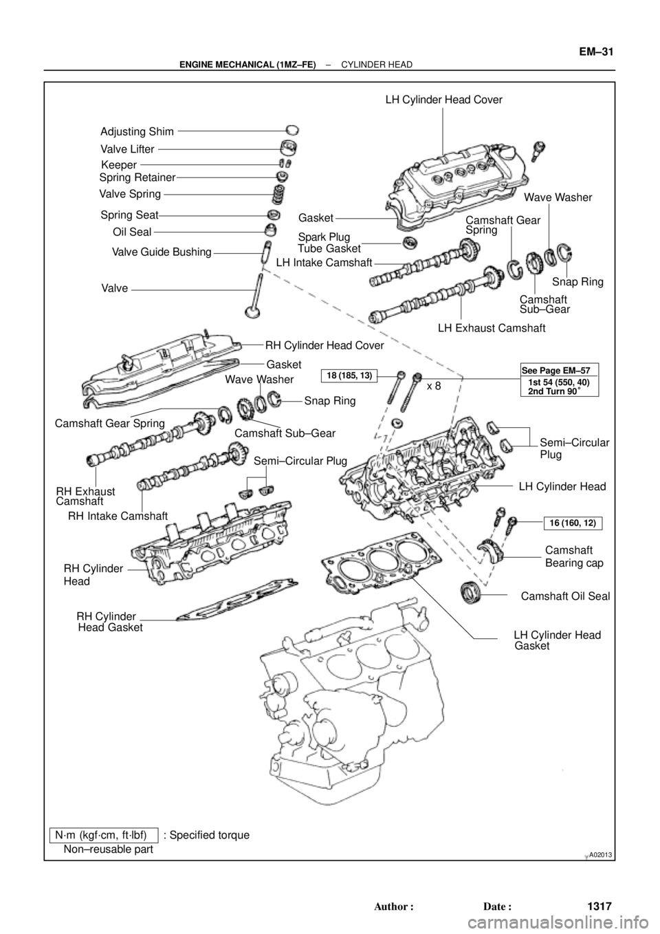
CYLINDER HEAD
COMPONENTS
Page 3534 of 4770

EGR Gas Temperature
Sensor Connector
Water Bypass Hose
A06657
PS Pressure TubeAir Intake Chamber Stay
V±Bank Cover
VSV Connector
for EGR
Engine Wire�Gasket
No.2 EGR Pipe
Throttle Position
Sensor Connector
Vacuum Hose
EGR Valve Position Brake Booster12 (120,9)
39 (400,29)
�Gasket
Sensor Connector
IAC Valve
ConnectorAccelerator Cable
Throttle Cable
Purge Hose
Air Assist Hose Hose Vacuum
�Gasket
VSV Connector for ACIS
Engine Coolant
Reservoir Hose
43 (440,32)
ECT Sender
Gauge Connector
ECT Sensor
Connector
Grand Strap
Connector
15 (150,11)
Water Outlet
15 (150,11)
Water Bypass
Hose
Upper Radiator
Hose
Fuel Inlet Hose
Injector Connector Intake Manifold Assembly�Retainer
Heater Hose
�Gasket Ignition Coil
Connector
� Non±reusable part: Specified torque
N´m (kgf´cm, ft´lbf)
19.5 (200, 14)
No.1 Engine
Hanger
VSV Connector for
EVAP
Ground Cable
PCV Hose Ground Cable
Air Intake Chamber
Assembly
� Gasket
High±Tension Cord Set
Spark PlugIgnition Coil
Water Bypass Hose
Ground Strap
DLC1
EM±28
± ENGINE MECHANICAL (1MZ±FE)CYLINDER HEAD
1314 Author�: Date�:
Page 3535 of 4770
A05070
Timing Belt
Gasket No.2 Timing Belt Cover
RH Engine Mounting Bracket
Crankshaft
Pulley No.1 Timing Belt Cover
Gasket
Engine Wire
Protector
No.2 Idler Pulley
RH Camshaft Timing Pulley
LH Camshaft
Timing Pulley
Timing Belt TensionerTiming Belt Guide
No.2 Generator
Bracket
Dust Boot
N´m (kgf´cm, ft´lbf) : Specified torque
* For use with SST� Non±reusable part
28 (290, 21)
215 (2,200, 159)
125 (1,300, 94)
*88 (900, 65)
27 (280, 20)
43 (440, 32)
125 (1,300, 94)
± ENGINE MECHANICAL (1MZ±FE)CYLINDER HEAD
EM±29
1315 Author�: Date�:
Page 3536 of 4770
Engine Wire
 ProtectorEngine Wire
Protector
Heated Oxygen Sensor
(Bank 1 Sensor 1)
Connector
RH Exhaust Manifold
(Except")
A06635� Non±reusable part: Specified torque
N´m (kgf´cm, ft´lbf)Engine Wire
Engine Wire ProtectorEngine Wire
Protector
Heated Oxygen Sensor
(Bank 1 Sensor 1)
Connector
RH Exhaust Manifold
(Except M/T and California A/T)
34 (350,25)
x 6
12 (120, 9)
PS Pump Bracket
43 (440, 32)
No.1 EGR Pipe � Gasket
Cylinder Head Rear Plate
Ground Strap
Water Inlet
Pipe � O±Ring
Gasket
20 (200, 14)
CollarBushing No.3 Timing
Belt Cover
x 6
x 6
� O±Ring
49 (500, 36)LH Exhaust
Manifold Stay
(Except M/T and
California A/T ) Oil Dipstick Guide Engine WireRH Exhaust Manifold
RH Exhaust
Manifold Stay
� Gasket
20 (200, 14)
Heated Oxygen Sensor
(Bank 2 Sensor 1)
Connector
34 (350,25)
49 (500, 36)
LH Exhaust
Manifold Stay
LH Exhaust Manifold
California A/T
M/T and California A/T
� Gasket
Camshaft
Position Sensor
ConnectorGasket RH
Exhaust
Manifold
Stay
(Except M/T and Calif. A/T)
Camshaft Position Sensor
LH Exhaust Manifold
(Except California A/T)
49 (500, 36)
x 6 EM±30
± ENGINE MECHANICAL (1MZ±FE)CYLINDER HEAD
1316 Author�: Date�:
Page 3537 of 4770
A02013
Adjusting Shim
Valve Lifter
Keeper
Spring Retainer
Valve Spring
Spring Seat
� Oil Seal
Valve � Valve Guide BushingLH Cylinder Head Cover
GasketWave Washer
Camshaft Gear
Spring
� Spark Plug
Tube Gasket
LH Intake Camshaft
Snap Ring
Camshaft
Sub±Gear
LH Exhaust Camshaft
RH Cylinder Head Cover
Gasket
RH Intake CamshaftCamshaft Sub±GearSnap Ring
Camshaft Gear Spring
RH Exhaust
CamshaftWave Washer
Semi±Circular PlugSemi±Circular
Plug
LH Cylinder Head
Camshaft
Bearing cap
� Camshaft Oil Seal RH Cylinder
Head
� RH Cylinder
Head Gasket
� LH Cylinder Head
Gasket x 8
N´m (kgf´cm, ft´lbf) : Specified torque
� Non±reusable part
18 (185, 13)
16 (160, 12) See Page EM±57
1st 54 (550, 40)
2nd Turn 90°
± ENGINE MECHANICAL (1MZ±FE)CYLINDER HEAD
EM±31
1317 Author�: Date�:
Page 3555 of 4770
CYLINDER HEAD
EM±49
1335 Author�: Date�:
17. INSPECT CAMSHAFT JOURNAL OIL CLEARANCE
(a) Clean the bearing caps and camshaft journa")
P13009
Plastigage
P12892
P13004
P12891
± ENGINE MECHANICAL (1MZ±FE)CYLINDER HEAD
EM±49
1335 Author�: Date�:
17. INSPECT CAMSHAFT JOURNAL OIL CLEARANCE
(a) Clean the bearing caps and camshaft journals.
(b) Place the camshafts on the cylinder head.
(c) Lay a strip of Plastigage across each of the camshaft jour-
nal.
(d) Install the bearing caps. (See page EM±57)
Torque: 16 N´m (160 kgf´cm, 12 ft´lbf)
NOTICE:
Do not turn the camshaft.
(e) Remove the bearing caps.
(f) Measure the Plastigage at its widest point.
Standard oil clearance:
Intake0.035 ± 0.072 mm (0.0014 ± 0.0028 in.)
Exhaust0.025 ± 0.062 mm (0.0010 ± 0.0024 in.)
Maximum oil clearance:
Intake0.10 mm (0.0039 in.)
Exhaust0.09 mm (0.0035 in.)
If the oil clearance is greater than maximum, replace the cam-
shaft. If necessary, replace the bearing caps and cylinder head
as a set.
(g) Completely remove the Plastigage.
(h) Remove the camshafts.
18. INSPECT CAMSHAFT THRUST CLEARANCE
(a) Install the camshafts. (See page EM±57)
(b) Using a dial indicator, measure the thrust clearance while
moving the camshaft back and forth.
Standard thrust clearance:
0.040 ± 0.090 mm (0.0016 ± 0.0035 in.)
Maximum thrust clearance: 0.12 mm (0.0047 in.)
If the thrust clearance is greater than maximum, replace the
camshaft. If necessary, replace the bearing caps and cylinder
head as a set.