Page 3471 of 4770
ENGINE UNIT
EM±79
1251 Author�: Date�:
A/T:
Install the 4 bolts.
Torque: 64 N´m (650 kgf´cm, 47 ft´lbf)
24. REMOVE ENGINE SLI")
S04616
A/T
S05246
S05250
Connector
S05253
± ENGINE MECHANICAL (5S±FE)ENGINE UNIT
EM±79
1251 Author�: Date�:
A/T:
Install the 4 bolts.
Torque: 64 N´m (650 kgf´cm, 47 ft´lbf)
24. REMOVE ENGINE SLING DEVICE
25. CONNECT TRANSAXLE CONTROL CABLE(S) TO
TRANSAXLE
26. INSTALL PS PUMP
(a) Install the PS pump with the 2 bolts.
Torque: 43 N´m (440 kgf´cm, 32 ft´lbf)
(b) Install the drive belt.
(c) Connect the PS oil pressure switch connector.
27. INSTALL A/C COMPRESSOR
(a) Install the cylinder block insulator and A/C compressor
with the 3 bolts.
Torque: 25.5 N´m (260 kgf´cm, 19 ft´lbf)
(b) Install the drive belt.
(c) Connect the A/C compressor connector.
28. M/T:
INSTALL CLUTCH RELEASE CYLINDER AND TUBE
TO TRANSAXLE
29. M/T:
INSTALL STARTER (See page ST±19)
30. INSTALL DRIVE SHAFTS (See page SA±24)
31. CONNECT ENGINE WIRE TO CABIN
(a) Push in the engine wire through the cowl panel. Install the
grommet.
(b) Connect the 3 engine ECM connectors.
(c) Connect the 3 cowl wire connectors to the connectors on
the bracket.
(d) Install the under cover.
32. CONNECT CONNECTORS, WIRES, CABLES,
CLAMPS AND HOSES
(a) Connect the generator wire.
Page 3472 of 4770
ENGINE UNIT
1252 Author�: Date�:
(b) Connect the generator connector.
(c) Install the wire clamp to the generator.
(d) Connect the starter cable.
(e) Connect")
S05251
EM±80
± ENGINE MECHANICAL (5S±FE)ENGINE UNIT
1252 Author�: Date�:
(b) Connect the generator connector.
(c) Install the wire clamp to the generator.
(d) Connect the starter cable.
(e) Connect the starter connector.
(f) Install the DLC1 to the bracket.
(g) Install the engine wire clamp to the bracket on the RH
fender apron.
(h) Connect the MAP sensor connector.
(i) Install the wire clamp to the bracket for the MAP sensor.
(j) Connect the VSV connector for the vapor pressure sen-
sor.
(k) Connect the 2 ground strap connectors to the RH fender
apron.
(l) Connect the 2 ground strap connectors to the LH fender
apron.
(m) Install the engine wire protector clamp to the battery
bracket.
(n) Install the engine wire to the clamp on the fuel filter.
(o) Connect the ground cable to the transaxle.
(p) Connect the brake booster vacuum hose to the intake
manifold.
(q) Connect the heater hose to the water outlet.
(r) Connect the heater hose to the water bypass pipe.
(s) Connect the fuel inlet hose to the fuel filter with 2 new gas-
kets and the union bolt.
Torque: 29 N´m (300 kgf´cm, 21 ft´lbf)
(t) Connect the MAP sensor vacuum hose to the gas filter on
the intake manifold.
33. INSTALL FRONT EXHAUST PIPE
(a) Install the support bracket with the nut.
Torque: 33 N´m (330 kgf´cm, 24 ft´lbf)
(b) Temporarily install 2 new gaskets and the front exhaust
pipe with the 2 bolts and 5 nuts.
(c) Tighten the 3 nuts holding the exhaust manifold to the
front exhaust pipe.
Torque: 62 N´m (630 kgf´cm, 46 ft´lbf)
(d) Tighten the 2 bolts and 2 nuts holding the front exhaust
pipe to the center exhaust pipe.
Torque: 56 N´m (570 kgf´cm, 41 ft´lbf)
(e) Install the bracket with the 2 bolts.
Torque: 33 N´m (330 kgf´cm, 24 ft´lbf)
(f) Install the support stay with the 2 bolts.
Torque: 33 N´m (330 kgf´cm, 24 ft´lbf)
34. INSTALL RADIATOR (See page CO±23)
35. INSTALL CRUISE CONTROL ACTUATOR
36. INSTALL BATTERY TRAY AND BATTERY
37. INSTALL AIR CLEANER CASE
Install the air cleaner case with the 3 bolts.
Page 3474 of 4770
EM08H±03
A07366
No.2 Timing Belt
Cover
No.1 Timing Belt
Cover
Crankshaft
Pulley
No.2 Idler PulleyTension Spring* Gasket
Timing Belt Guide Timing Belt
High±Tension Cord
Spark Plug
N´m (kgf´cm, ft´lbf)Wire
ClampGenerator
Wire Clamp
Crankshaft Timing Pulley
Camshaft Timing Pulley
No.1 Idler PulleyWire ClampWire Clamp
108 (1,100, 80)
54 (550, 40)
42 (425, 31)
18 (180, 13)
42 (425, 31)
: Specified torque* Gasket
* Replace only if damaged
EM±82
± ENGINE MECHANICAL (5S±FE)CYLINDER BLOCK
1254 Author�: Date�:
CYLINDER BLOCK
COMPONENTS
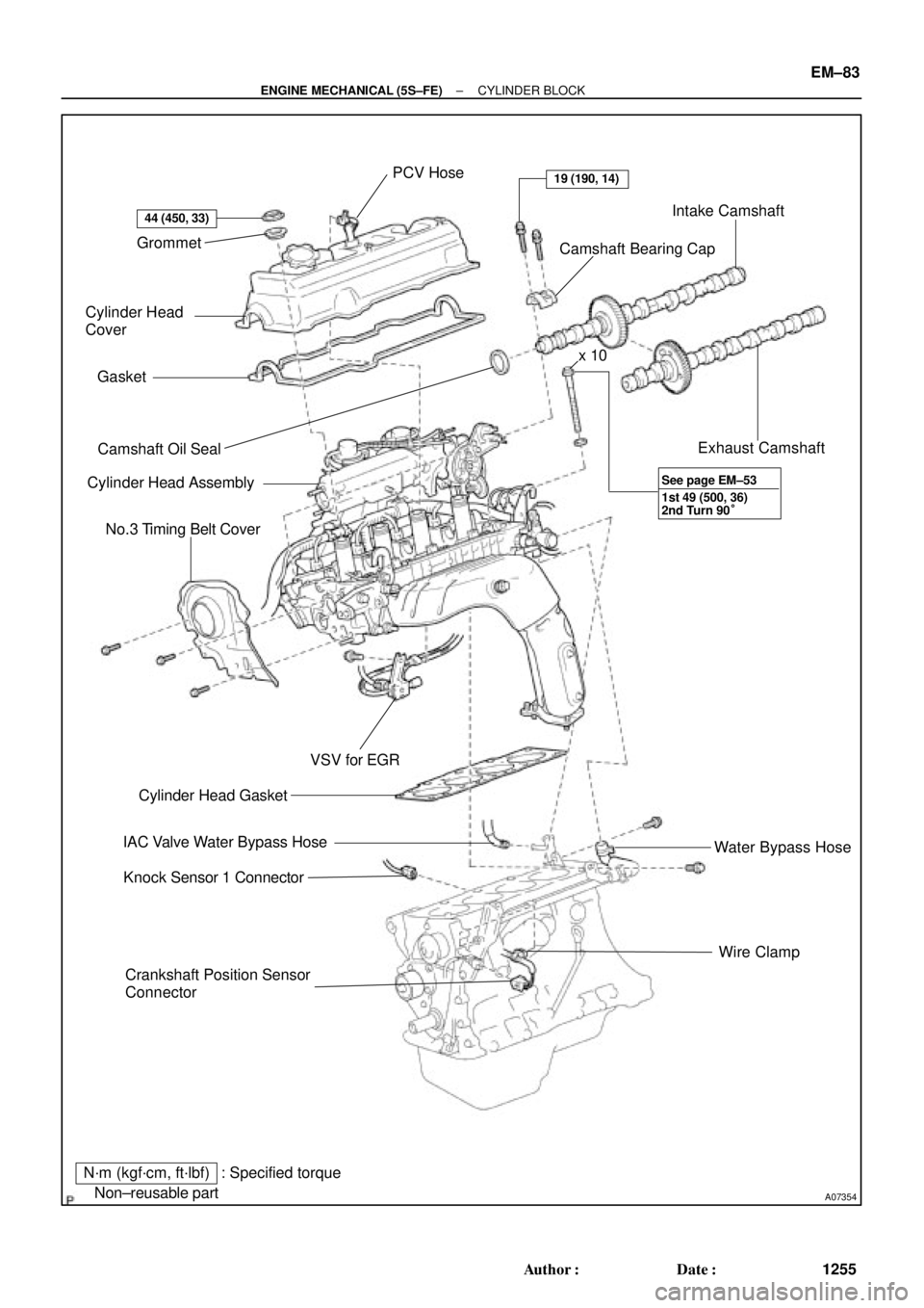
Page 3475 of 4770
A07354
Grommet
Cylinder Head
Cover
Gasket
� Camshaft Oil Seal
Cylinder Head Assembly
No.3 Timing Belt Cover
Crankshaft Position Sensor
ConnectorWire Clamp Water Bypass Hose Exhaust Camshaft Intake Camshaft
Camshaft Bearing Cap PCV Hose
� Cylinder Head Gasket
IAC Valve Water Bypass Hose
Knock Sensor 1 Connector
N´m (kgf´cm, ft´lbf)
� Non±reusable part
44 (450, 33)
19 (190, 14)
VSV for EGR
: Specified torquex 10
1st 49 (500, 36)
2nd Turn 90° See page EM±53
± ENGINE MECHANICAL (5S±FE)CYLINDER BLOCK
EM±83
1255 Author�: Date�:
Page 3476 of 4770
A07367
Water Pump, Water Bypass Pipe
and Oil Cooler Assembly
Water Pump and Water
Bypass Pipe Assembly
(w/o Oil Cooler)
Union Bolt
Generator Drive Belt Adjusting Bar
Knock Sensor 1Oil Filter
Oil Dipstick
PS Pump
Bracket
Crankshaft Position Sensor Connector
Oil Pump
� Gasket x 10
Oil Strainer
Oil Pan
Drain Plug
N´m (kgf´cm, ft´lbf)
� Non±reusable partx 17 � Gasket
� Gasket � O±Ring
8.8 (90, 78 in.´lbf)5.4 (55, 48 in.´lbf)
5.4 (55, 48 in.´lbf)
� O±Ring
78.5 (800, 58)
w/ Oil Cooler
: Specified torque
Crankshaft
Front Oil
Seal �
EM±84
± ENGINE MECHANICAL (5S±FE)CYLINDER BLOCK
1256 Author�: Date�:
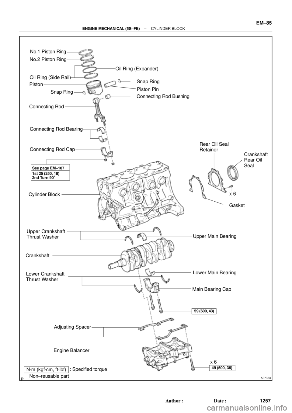
Page 3477 of 4770
A07353
No.1 Piston Ring
No.2 Piston Ring
Oil Ring (Side Rail)
� Snap Ring
Connecting Rod
Connecting Rod Bearing
Connecting Rod Cap
Cylinder Block
Upper Crankshaft
Thrust Washer
Crankshaft
Lower Crankshaft
Thrust Washer
Adjusting Spacer
Engine Balancerx 6
Main Bearing CapLower Main Bearing Upper Main Bearing� Gasket Rear Oil Seal
Retainer
Crankshaft
Rear Oil
Seal � Connecting Rod BushingPiston Pin � Snap Ring Oil Ring (Expander)
� Non±reusable part
N´m (kgf´cm, ft´lbf)x 6 Piston
1st 25 (250, 18)
2nd Turn 90°
59 (600, 43)
49 (500, 36): Specified torque
See page EM±107
�
± ENGINE MECHANICAL (5S±FE)CYLINDER BLOCK
EM±85
1257 Author�: Date�:
Page 3501 of 4770
CYLINDER BLOCK
EM±109
1281 Author�: Date�:
(b) Align the bearing claw with the claw groove of the")
P03177
Mark
1, 2, 3, 4, or 5
P05354
P03173
S06012
P00104
1
10
735
84269
± ENGINE MECHANICAL (5S±FE)CYLINDER BLOCK
EM±109
1281 Author�: Date�:
(b) Align the bearing claw with the claw groove of the main
bearing cap, and push in the 5 lower bearings.
HINT:
A number is marked on each main bearing cap to indicate the
installation position.
5. INSTALL UPPER THRUST WASHERS
Install the 2 thrust washers under the No.3 journal position of
the cylinder block with the oil grooves facing outward.
6. PLACE CRANKSHAFT ON CYLINDER BLOCK
7. INSTALL MAIN BEARING CAPS AND LOWER
THRUST WASHERS
(a) Install the 2 thrust washers on the No.3 bearing cap with
the grooves facing outward.
(b) Install the 5 main bearing caps in their proper locations.
HINT:
Each bearing cap has a number and front mark.
(c) Apply a light coat of engine oil on the threads and under
the heads of the main bearing cap bolts.
(d) Install and uniformly tighten the 10 bolts of the main bear-
ing cap in several passes, in the sequence shown.
Torque: 59 N´m (600 kgf´cm, 43 ft´lbf)
(e) Check that the crankshaft turns smoothly.
8. CHECK CRANKSHAFT THRUST CLEARANCE
(See page EM±86)
Page 3502 of 4770

Front
N01001
Front Mark
(Protrusion)
Z19381
EM±110
± ENGINE MECHANICAL (5S±FE)CYLINDER BLOCK
1282 Author�: Date�:
9. INSTALL PISTON AND CONNECTING ROD AS-
SEM")
EM2082
A06614
Push Front Mark
(Cavity)
Front
N01001
Front Mark
(Protrusion)
Z19381
EM±110
± ENGINE MECHANICAL (5S±FE)CYLINDER BLOCK
1282 Author�: Date�:
9. INSTALL PISTON AND CONNECTING ROD AS-
SEMBLES
(a) Cover the connecting rod bolts with a short piece of hose
to protect the crankshaft from damage.
(b) Using a piston ring compressor, push the correctly num-
bered piston and connecting rod assemblies into each
cylinder with the front mark of the piston facing forward.
10. PLACE CONNECTING ROD CAP ON CONNECTING
ROD
(a) Match the numbered connecting rod cap with the con-
necting rod.
(b) Install the connecting rod cap with the front mark facing
forward.
11. INSTALL CONNECTING ROD CAP NUTS
HINT:
�The cap nuts are tightened in 2 progressive steps (steps
(b) and (d)).
�If any one of the connecting rod bolts is broken or de-
formed, replace it.
(a) Apply a light coat of engine oil on the threads and under
the nuts of the connecting rod cap.
(b) Install and alternately tighten the 2 cap nuts in several
passes.
Torque: 25 N´m (250 kgf´cm, 18 ft´lbf)
If any one of the cap nuts does not meet the torque specifica-
tion, replace the connecting rod bolt and cap nut as a set.


Union Bolt
Generator Drive Belt Adjusting Bar
Knock Sensor 1Oil Filter
Oil Dipst")