Page 3739 of 4770
B04401
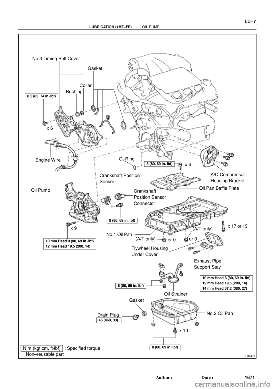
N´m (kgf´cm, ft´lbf) : Specified torque
� Non±reusable partNo.3 Timing Belt Cover
Gasket
BushingCollar
A/C Compressor
Housing Bracket
Oil Pan Baffle Plate
Crankshaft
Position Sensor
Connector Crankshaft Position
Sensor
Oil PumpEngine Wire
Flywheel Housing
Under Cover
Exhaust Pipe
Support Stay
Oil Strainer
No.2 Oil Pan
x 10x 6
x 9� O±Ring
No.1 Oil Pan
� Gasket
Drain Plug
8.5 (85, 74 in.´lbf)
8 (80, 69 in.´lbf)
8 (80, 69 in.´lbf)
10 mm Head 8 (80, 69 in.´lbf)
12 mm Head 19.5 (200, 14)
10 mm Head 8 (80, 69 in.´lbf)
12 mm Head 19.5 (200, 14)
14 mm Head 37.2 (380, 27)
8 (80, 69 in.´lbf)
45 (460, 33)
8 (80, 69 in.´lbf)
x 6
x 17 or 19
(A/T only)(A/T only)or 0or 0
± LUBRICATION (1MZ±FE)OIL PUMP
LU±7
1671 Author�: Date�:
Page 3740 of 4770
B01016
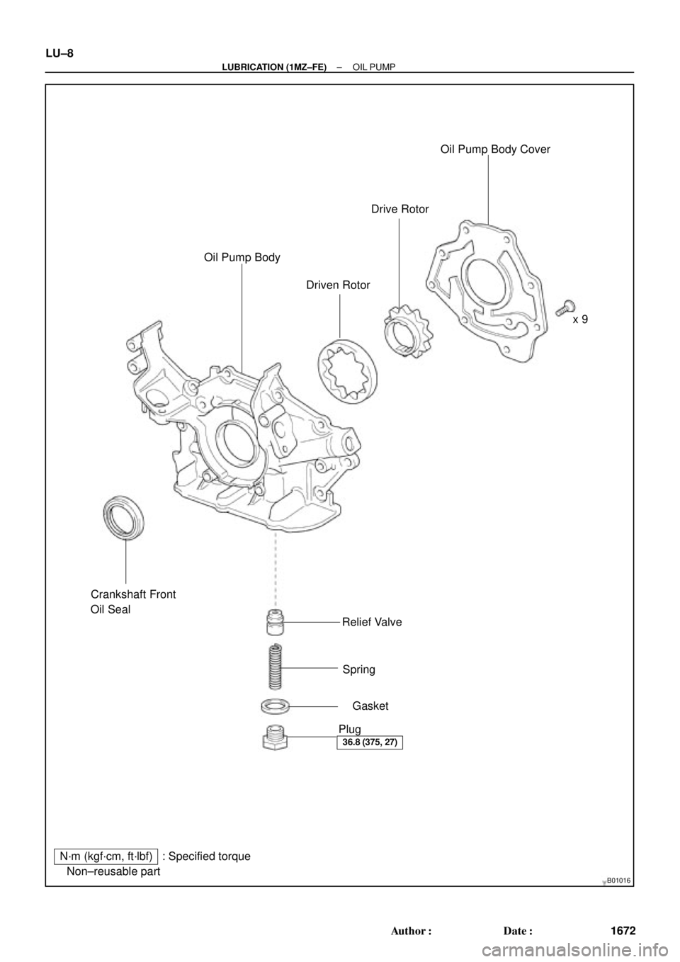
N´m (kgf´cm, ft´lbf) : Specified torque
� Non±reusable partx 9
� Gasket � Crankshaft Front
Oil Seal
Relief Valve
Spring
Plug Oil Pump Body
Driven RotorDrive RotorOil Pump Body Cover
36.8 (375, 27)
LU±8
± LUBRICATION (1MZ±FE)OIL PUMP
1672 Author�: Date�:
Page 3746 of 4770
LU02C±03
P12807
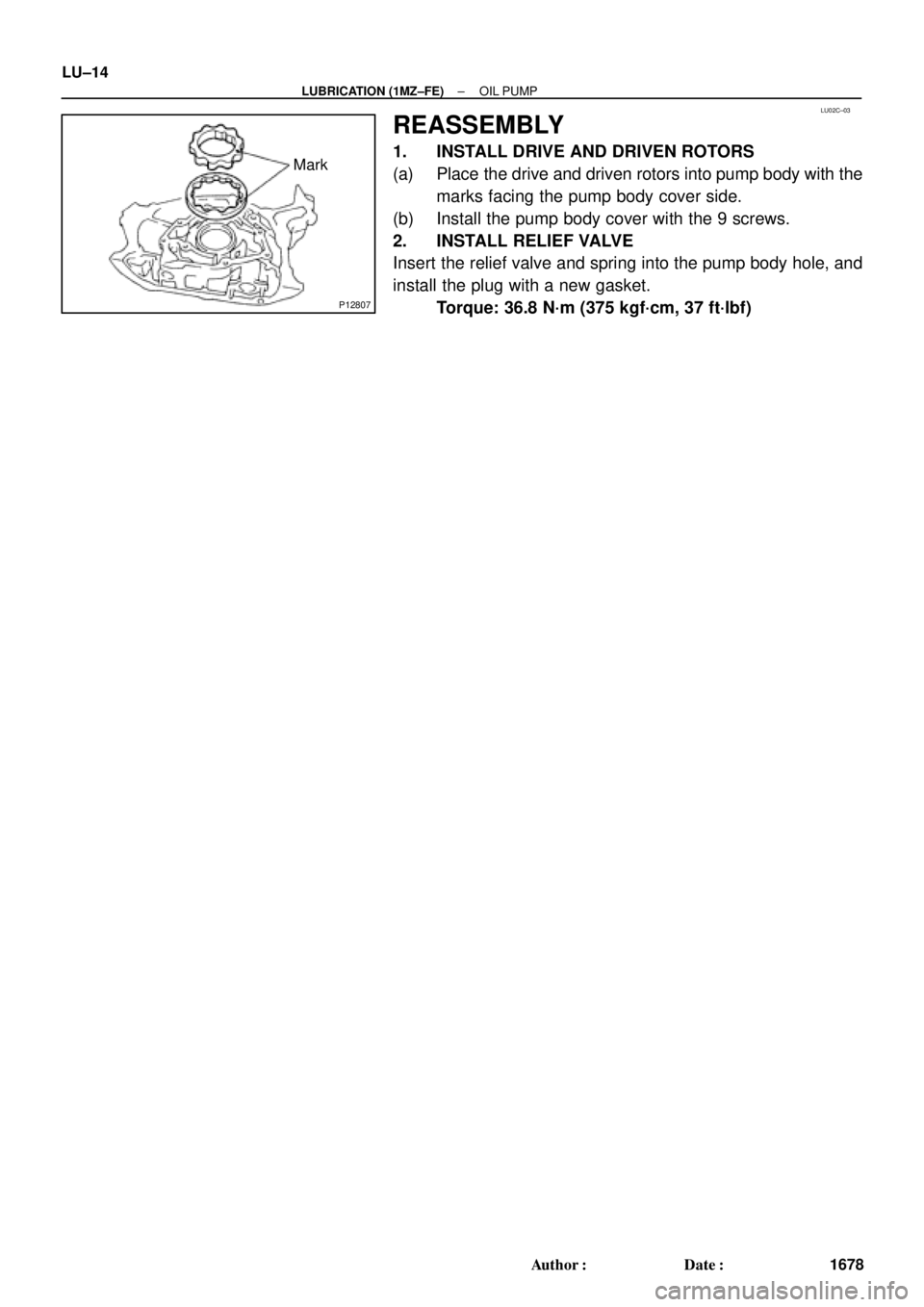
Mark LU±14
± LUBRICATION (1MZ±FE)OIL PUMP
1678 Author�: Date�:
REASSEMBLY
1. INSTALL DRIVE AND DRIVEN ROTORS
(a) Place the drive and driven rotors into pump body with the
marks facing the pump body cover side.
(b) Install the pump body cover with the 9 screws.
2. INSTALL RELIEF VALVE
Insert the relief valve and spring into the pump body hole, and
install the plug with a new gasket.
Torque: 36.8 N´m (375 kgf´cm, 37 ft´lbf)
Page 3748 of 4770
P12694
LU±16
± LUBRICATION (1MZ±FE)OIL PUMP
1680 Author�: Date�:
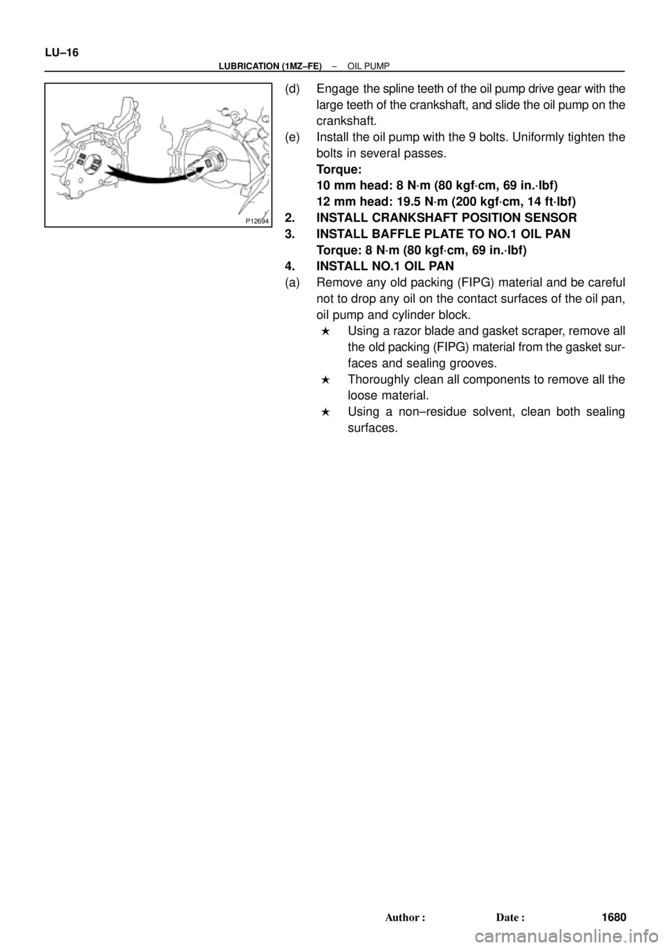
(d) Engage the spline teeth of the oil pump drive gear with the
large teeth of the crankshaft, and slide the oil pump on the
crankshaft.
(e) Install the oil pump with the 9 bolts. Uniformly tighten the
bolts in several passes.
Torque:
10 mm head: 8 N´m (80 kgf´cm, 69 in.´lbf)
12 mm head: 19.5 N´m (200 kgf´cm, 14 ft´lbf)
2. INSTALL CRANKSHAFT POSITION SENSOR
3. INSTALL BAFFLE PLATE TO NO.1 OIL PAN
Torque: 8 N´m (80 kgf´cm, 69 in.´lbf)
4. INSTALL NO.1 OIL PAN
(a) Remove any old packing (FIPG) material and be careful
not to drop any oil on the contact surfaces of the oil pan,
oil pump and cylinder block.
�Using a razor blade and gasket scraper, remove all
the old packing (FIPG) material from the gasket sur-
faces and sealing grooves.
�Thoroughly clean all components to remove all the
loose material.
�Using a non±residue solvent, clean both sealing
surfaces.
Page 3749 of 4770
OIL PUMP
LU±17
1681 Author�: Date�:
(b) Appl")
B04402
A Region ºXºRegion ºYº
A
CB B
C
Seal Width
Type A: 4 ± 5 mm
Type B: 3 ± 4 mmRegion ºXºRegion ºYº
AC Type A
Type B
± LUBRICATION (1MZ±FE)OIL PUMP
LU±17
1681 Author�: Date�:
(b) Apply seal packing to the oil pan as shown in the illustra-
tion.
Seal packing: Part No. 08826±00080 or equivalent
Region ºXº is at the outer side of the bolt hole.
Region ºYº is at the inner side of the bolt hole.
�Install a nozzle that has been cut to a 4 ± 5 mm (0.16
± 0.20 in.) (Type A) or 3 ± 4 mm (0.12 ± 0.16 in.)
(Type B) opening.
HINT:
Avoid applying an excessive amount to the surface.
�Parts must be assembled within 3 minutes of ap-
plication. Otherwise the material must be removed
and reapplied.
�Immediately remove nozzle from the tube and rein-
stall cap.
(c) Install the oil pan with the 19 bolts (or 17 bolts and 2 nuts).
Uniformly tighten the bolts and nuts in several passes.
Torque:
10 mm head: 8 N´m (80 kgf´cm, 69 in.´lbf)
12 mm head: 19.5 N´m (200 kgf´cm, 14 ft´lbf)
14 mm head: 37.2 N´m (380 kgf´cm, 27 ft´lbf)
(d) Install the flywheel housing under cover and exhaust pipe
support stay with the 2 bolts.
Torque: 7.8 N´m (80 kgf´cm, 69 in.´lbf)
5. INSTALL OIL STRAINER
Install a new gasket and the oil strainer with the bolt and 2 nuts.
Torque: 8 N´m (80 kgf´cm, 69 in.´lbf)
6. INSTALL NO.2 OIL PAN
(a) Remove any old packing (FIPG) material and be careful
not to drop any oil on the contact surface of the No.1 and
No.2 oil pans.
�Using a razor blade and gasket scraper, remove all
the old packing (FIPG) material from the gasket sur-
faces and sealing grooves.
�Thoroughly clean all components to remove all the
loose material.
�Using a non±residue solvent, clean both sealing
surfaces.
NOTICE:
Do not use a solvent which will affect the painted surfaces.
Page 3750 of 4770
OIL PUMP
1682 Author�: Date�:
(b) Apply seal packing to the No.2 oil pan as shown in the il-
lustration.
Seal packing:
Part No. 08826�")
P12568
A
A
BB
Seal Width
4 ± 5 mm LU±18
± LUBRICATION (1MZ±FE)OIL PUMP
1682 Author�: Date�:
(b) Apply seal packing to the No.2 oil pan as shown in the il-
lustration.
Seal packing:
Part No. 08826±00080 or equivalent
�Install a nozzle that has been cut to a 4 ± 5 mm (0.16
± 0.20 in.) opening.
HINT:
Avoid applying an excessive amount to the surface.
�Parts must be assembled within 3 minutes of ap-
plication. Otherwise the material must be removed
and reapplied.
�Immediately remove nozzle from the tube and rein-
stall cap.
(c) Install the No.2 oil pan with the 10 bolts and 2 nuts. Uni-
formly tighten the bolts and nuts in several passes.
Torque: 8 N´m (80 kgf´cm, 69 in.´lbf)
7. INSTALL A/C COMPRESSOR HOUSING BRACKET
Torque: 25 N´m (250 kgf´cm, 18 ft´lbf)
8. INSTALL NO.3 TIMING BELT COVER
(See page EM±21)
9. INSTALL TIMING PULLEYS (See page EM±21)
10. INSTALL TIMING BELT (See page EM±21)
11. INSTALL ADJUSTING STRUT AND PS PUMP DRIVE
BELT
(a) Temporarily install the adjusting strut with the bolt and the
nut.
(b) Install the drive belt with the pivot and adjusting bolts.
Torque: 43.1 N´m (440 kgf´cm, 32 ft´lbf)
(c) Tighten the nut.
Torque: 43.1 N´m (440 kgf´cm, 32 ft´lbf)
12. INSTALL A/C COMPRESSOR (See page AC±47)
13. INSTALL GENERATOR DRIVE BELT
(See page CH±16)
14. INSTALL FRONT EXHAUST PIPE BRACKET TO
NO.1 OIL PAN
Torque: 21 N´m (210 kgf´cm, 15 ft´lbf)
15. INSTALL FRONT EXHAUST PIPE (See page EM±76)
16. REMOVE RH FENDER APRON SEAL
17. REMOVE RH FRONT WHEEL
18. FILL ENGINE WITH OIL
19. START ENGINE AND CHECK FOR LEAKS
20. RECHECK ENGINE OIL LEVEL
Page 3758 of 4770

MA0676B00995
MA00O±01
N21126
N21125
MA±8
± MAINTENANCEBODY
51 Author�: Date�:
BODY
INSPECTION
1. TIGHTEN BOLTS AND NUTS ON CHASSIS AND
BODY
Tighten these parts:
�Front seat mount bolts
Torque: 37 N´m (375 kgf´cm, 27 ft´lbf)
�Front suspension member±to±body mounting bolts
Torque: 181 N´m (1,850 kgf´cm, 134 ft´lbf)
�Rear suspension member±to±body mounting nuts
Torque: 51 N´m (520 kgf´cm, 38 ft´lbf)
Check that the brakes work properly and do not drag.
2. FINAL INSPECTION
(a) Check the operation of the body parts:
�Hood:
Auxiliary catch operates properly
Hood locks securely when closed
�Front and rear doors:
Door lock operates properly
Doors close properly
�Luggage compartment door and back door:
Door lock operates properly
�Seats:
Seat adjusts easily and locks securely in any posi-
tion
Front seat back locks securely in any position
Folding±down rear seat backs lock securely
(b) Road test:
�Check the engine and chassis for abnormal noises.
�Check that the vehicle does not wander or pull to
one side.
Page 3762 of 4770

MX04C±01
Q09998
Hood
ClipCruise Control Actuator
Control Cable
Clutch Line
Bracket
Clutch Release CylinderWasher
RH Drive Shaft
Snap Ring
RH Stiffener
Plate
Ground Cable
Starter
Battery
Snap Ring
LH Drive Shaft�
RH Fender Apron
Seal
LH Stiffener Plate
Manifold StayTransaxle Back±Up Light Switch
Connector
Rear End Plate with Oil Pan
InsulatorAir Cleaner
Case Assembly
with Air Hose
Vehicle Speed Sensor
Connector
No.1 Fuel Tube Protector Engine LH
Mounting Insulator
with Bracket
Rear RH Suspension Member Brace
PS Gear Assembly
Lock Cap
Rear LH Suspension Member Brace Manifold StayClip
LH Fender Apron
Seal
Suspension Member with
Lower Suspension Arm
Front RH Suspension
Member BraceStabilizer Bar Link
Front Exhaust PipeCotter Pin
RH Fender
Liner
LH Fender Liner
Exhaust Pipe BracketNo.1 Exhaust Pipe
Support Bracket
: Specified torque
Non±reusable partGasket w/ Cruise Control:
�
�
�
Cotter Pin
�
Hole
Plug
�
�
Engine Rear Side Shutter PlateHold±Down
Clamp
Hole
Plug
12 (120, 9)
13 (130, 9)
46 (470, 34)
39 (400, 29)
6.9 (70, 61 in.´lbf)
14 (145, 10)
12 (120, 9)
39 (400, 29)
39 (400, 29)
64 (650, 47)
56 (570, 41)
37 (380, 27)
9.3 (95, 82 in.´lbf)
42 (425, 31)
32 (330, 24)
Silver Bolt: 44 (450, 33)
Green Bolt: 66 (670, 48)
62 (630, 46)
64 (650, 47)
64 (650, 47)
37 (380, 27)
181 (1,850, 134)
181 (1,850, 134)
181 (1,850, 134)
36 (370, 27)
10 (100, 7)
32 (330, 24)19 (195, 14)
49 (500, 36)
294 (3,000, 217)
Silver Bolt: 44 (450, 33)
Green Bolt: 66 (670, 48)
36 (370, 27)66 (670, 48)
39 (400, 29)
127 (1,300, 94)
33 (330, 24)
33 (330, 24)
19 (195, 14)
80 (820, 59)
Gasket�
�� �
Steering Return Pipe
Front LH
Suspension
Member Brace
N´m (kgf´cm, ft´lbf)
± MANUAL TRANSAXLE (S51)MANUAL TRANSAXLE UNIT
MX±3
1853 Author�: Date�:
MANUAL TRANSAXLE UNIT
COMPONENTS