Page 3474 of 4770
EM08H±03
A07366
No.2 Timing Belt
Cover
No.1 Timing Belt
Cover
Crankshaft
Pulley
No.2 Idler PulleyTension Spring* Gasket
Timing Belt Guide Timing Belt
High±Tension Cord
Spark Plug
N´m (kgf´cm, ft´lbf)Wire
ClampGenerator
Wire Clamp
Crankshaft Timing Pulley
Camshaft Timing Pulley
No.1 Idler PulleyWire ClampWire Clamp
108 (1,100, 80)
54 (550, 40)
42 (425, 31)
18 (180, 13)
42 (425, 31)
: Specified torque* Gasket
* Replace only if damaged
EM±82
± ENGINE MECHANICAL (5S±FE)CYLINDER BLOCK
1254 Author�: Date�:
CYLINDER BLOCK
COMPONENTS
Page 3478 of 4770
CYLINDER BLOCK
1258 Author�: Date�:
DISASSEMBLY
1. INSTALL ENGINE TO ENGINE STAND FOR DIS-
ASSEMBLY
2. REMOVE TIMING BELT AND PULLEYS
(See pa")
EM0YW±01
S06011
1
3
2 EM±86
± ENGINE MECHANICAL (5S±FE)CYLINDER BLOCK
1258 Author�: Date�:
DISASSEMBLY
1. INSTALL ENGINE TO ENGINE STAND FOR DIS-
ASSEMBLY
2. REMOVE TIMING BELT AND PULLEYS
(See page EM±17)
3. REMOVE CYLINDER HEAD ASSEMBLY
(a) Remove the 3 bolts and No.3 timing belt cover.
(b) Remove the cylinder head cover.
(1) Disconnect the PCV hose from the intake manifold.
(2) Remove the 4 nuts, 4 grommets, head cover and
gasket.
(c) Remove the camshafts. (See page EM±33)
(d) Disconnect the knock sensor 1 connector.
(e) Disconnect the crankshaft position sensor connector.
(f) Disconnect the wire clamp from the generator drive belt
adjusting bar.
(g) Disconnect the IAC valve water bypass hose from the wa-
ter bypass pipe.
(h) Disconnect the water bypass hose (from the water by-
pass pipe) from the water outlet.
(i) Remove the bolt holding the VSV for EGR to the intake
manifold.
(j) Remove the 2 bolts holding the water bypass pipe to the
cylinder head.
(k) Remove the cylinder head assembly.
(See page EM±33)
4. REMOVE OIL DIPSTICK
5. REMOVE OIL PAN AND OIL PUMP
(a) Disconnect the crankshaft position sensor connector
from the generator drive belt adjusting bar.
(b) Remove the oil pan and oil pump. (See page LU±7)
6. REMOVE PS PUMP BRACKET
Remove the 3 bolts and pump bracket.
7. REMOVE KNOCK SENSOR 1 (See page SF±57)
8. REMOVE OIL FILTER (See page LU±2)
9. REMOVE WATER PUMP, WATER BYPASS PIPE AND
OIL COOLER (w/ OIL COOLER) ASSEMBLY
(a) w/ Oil Cooler:
Remove the nut and union bolt, and disconnect the oil
cooler. Remove the O±ring.
(b) Remove the bolt and generator drive belt adjusting bar.
(c) Remove the 3 bolts in the sequence shown, remove the
water pump, water bypass pipe, oil cooler (w/ oil cooler)
assembly and O±ring.
Page 3503 of 4770
CYLINDER BLOCK
EM±111
1283 Author�: Date�:
(c) Mark the front of")
S02826
Front 90°Painted Mark
90°
S05945
Pulley
Set
Key
Cylinder
Block Top
Surface
P01478
P00716
P00733
± ENGINE MECHANICAL (5S±FE)CYLINDER BLOCK
EM±111
1283 Author�: Date�:
(c) Mark the front of the cap nut with the paint.
(d) Retighten the cap nuts 90° as shown.
(e) Check that the painted mark is now at a 90° angle to the
front.
(f) Check that the crankshaft turns smoothly.
12. CHECK CONNECTING ROD THRUST CLEARANCE
(See page EM±86)
13. INSTALL ENGINE BALANCER
(a) Turn the crankshaft, and set the No.1 cylinder TDC as
shown in the illustration.
(b) Set the balance shafts so that the punch marks of the bal-
ance shafts are aligned with the grooves of the
No.2 housing.
(c) Wipe clean the installation surface of the spacer.
(d) Place the spacers on the cylinder block.
HINT:
When replacing the crankshaft and/or balance shaft, use the
thickest spacers.
(e) Place the engine balancer on the cylinder block.
(f) Check that punch marks shown in the illustration of the
balance shafts are aligned with the grooves of the No.2
housing.
Page 3510 of 4770
VALVE CLEARANCE
1290 Author�: Date�:
VALVE CLEARANCE
INSPECTION
HINT:
Inspect and adjust the val")
EM04K±04
P18805
P13074
RH EX
RH IN
LH IN
LH EX 13
6
23
1
6
2Front EM±4
± ENGINE MECHANICAL (1MZ±FE)VALVE CLEARANCE
1290 Author�: Date�:
VALVE CLEARANCE
INSPECTION
HINT:
Inspect and adjust the valve clearance when the engine is cold.
1. REMOVE RH FENDER APRON SEAL
2. DRAIN ENGINE COOLANT
3. REMOVE V±BANK COVER
(a) Using a 5 mm hexagon wrench, remove the 2 nuts.
(b) Disconnect the 2 clips, and remove the cover.
4. REMOVE HIGH±TENSION CODE SET
(See page IG±7)
5. REMOVE AIR INTAKE CHAMBER ASSEMBLY
(See page EM±32)
6. REMOVE IGNITION COILS
7. DISCONNECT RADIATOR HOSE FROM WATER
OUTLET
8. REMOVE CYLINDER HEAD COVERS
(See page EM±32)
9. SET NO.1 CYLINDER TO TDC/COMPRESSION
(a) Turn the crankshaft pulley, and align its groove with the
timing mark º0º of the No.1 timing belt cover.
(b) Check that the valve lifters on the No.1 (IN and EX) are
loose.
If not, turn the crankshaft 1 revolution (360°) and align the mark
as above.
10. INSPECT VALVE CLEARANCE
(a) Check only those valves indicated in the illustration.
(1) Using a feeler gauge, measure the clearance be-
tween the valve lifter and camshaft.
(2) Record out of specification valve clearance mea-
surements. They will be used later to determine the
required replacement adjusting shim.
Valve clearance (Cold):
Intake0.15 ± 0.25 mm (0.006 ± 0.010 in.)
Exhaust0.25 ± 0.35 mm (0.010 ± 0.014 in.)
Page 3520 of 4770
B06384
No.2 Timing Belt CoverTiming Belt
Gasket
Timing Belt Guide
No.2 Generator
Bracket RH Engine Mounting Bracket
Crankshaft
PulleyGasket
Engine Wire
Protector
RH Camshaft Timing Pulley
No.2 Idler Pulley
Crankshaft
Timing PulleyDust Boot
Timing Belt Plate Plate Washer
�
Timing Belt Tensioner
N´m (kgf´cm, ft´lbf)
: Specified torque
� Non±reusable part No.1 Timing Belt Cover
LH Camshaft
Timing Pulley
No.1 Idler Pulley
� Precoated part
* For use with SST
28 (290, 21)
215 (2,200, 159)
125 (1,300, 94)*88 (900, 65)43 (440, 32)
34 (350, 25)
27 (280, 20)
125 (1,300, 94)
EM±14
± ENGINE MECHANICAL (1MZ±FE)TIMING BELT
1300 Author�: Date�:
Page 3521 of 4770
EM04O±04
P18754
P18816
P18817
SST
P18819
SST
± ENGINE MECHANICAL (1MZ±FE)TIMING BELT
EM±15
1301 Author�: Date�:
REMOVAL
1. REMOVE RH FRONT WHEEL
2. REMOVE RH FENDER APRON SEAL
3. REMOVE GENERATOR DRIVE BELT
(See page CH±6)
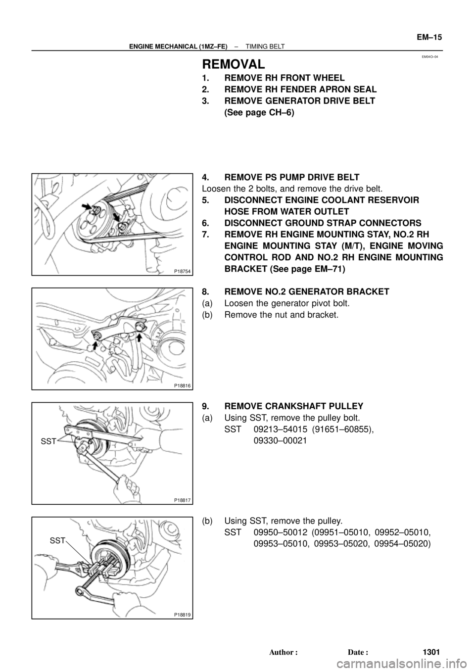
4. REMOVE PS PUMP DRIVE BELT
Loosen the 2 bolts, and remove the drive belt.
5. DISCONNECT ENGINE COOLANT RESERVOIR
HOSE FROM WATER OUTLET
6. DISCONNECT GROUND STRAP CONNECTORS
7. REMOVE RH ENGINE MOUNTING STAY, NO.2 RH
ENGINE MOUNTING STAY (M/T), ENGINE MOVING
CONTROL ROD AND NO.2 RH ENGINE MOUNTING
BRACKET (See page EM±71)
8. REMOVE NO.2 GENERATOR BRACKET
(a) Loosen the generator pivot bolt.
(b) Remove the nut and bracket.
9. REMOVE CRANKSHAFT PULLEY
(a) Using SST, remove the pulley bolt.
SST 09213±54015 (91651±60855),
09330±00021
(b) Using SST, remove the pulley.
SST 09950±50012 (09951±05010, 09952±05010,
09953±05010, 09953±05020, 09954±05020)
Page 3522 of 4770
P18820
A01800
Clamp
Clamp
P18814
P18808
A05052
EM±16
± ENGINE MECHANICAL (1MZ±FE)TIMING BELT
1302 Author�: Date�:
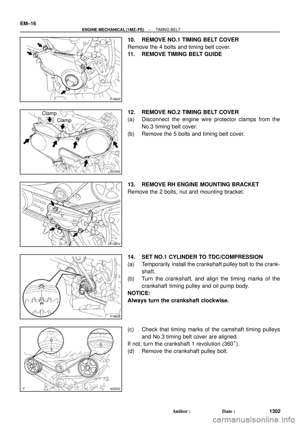
10. REMOVE NO.1 TIMING BELT COVER
Remove the 4 bolts and timing belt cover.
11. REMOVE TIMING BELT GUIDE
12. REMOVE NO.2 TIMING BELT COVER
(a) Disconnect the engine wire protector clamps from the
No.3 timing belt cover.
(b) Remove the 5 bolts and timing belt cover.
13. REMOVE RH ENGINE MOUNTING BRACKET
Remove the 2 bolts, nut and mounting bracket.
14. SET NO.1 CYLINDER TO TDC/COMPRESSION
(a) Temporarily install the crankshaft pulley bolt to the crank-
shaft.
(b) Turn the crankshaft, and align the timing marks of the
crankshaft timing pulley and oil pump body.
NOTICE:
Always turn the crankshaft clockwise.
(c) Check that timing marks of the camshaft timing pulleys
and No.3 timing belt cover are aligned.
If not, turn the crankshaft 1 revolution (360°).
(d) Remove the crankshaft pulley bolt.
Page 3524 of 4770
A01802
10 mm
Hexagon
Wrench
Plate Washer
P20026
SST EM±18
± ENGINE MECHANICAL (1MZ±FE)TIMING BELT
1304 Author�: Date�:
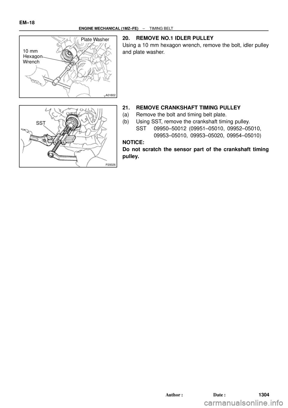
20. REMOVE NO.1 IDLER PULLEY
Using a 10 mm hexagon wrench, remove the bolt, idler pulley
and plate washer.
21. REMOVE CRANKSHAFT TIMING PULLEY
(a) Remove the bolt and timing belt plate.
(b) Using SST, remove the crankshaft timing pulley.
SST 09950±50012 (09951±05010, 09952±05010,
09953±05010, 09953±05020, 09954±05010)
NOTICE:
Do not scratch the sensor part of the crankshaft timing
pulley.