Page 521 of 4770

42ENGINEÐ5S±FE ENGINE
5. Main Components of Engine Control System
The following table compares the main components of the new 5S±FE engine, and previous 5S±FE engine.
Model
NewPreviousComponentNewPrevious
Manifold Absolute Pressure SensorSemiconductoru
Throttle Position SensorLinear Typeu
Crankshaft Position SensorPick±Up Coil Type, 1u
Camshaft Position SensorPick±Up Coil Type, 1Ð
DistributorCamshaft PositionPick Up Coil Type 1DistributorSensorÐPick±Up Coil Type, 1
Knock SensorBuilt±In Piezoelectric
Element Type 1u
Oxygen Sensor
Heated Oxygen Sensor
(Bank 1, Sensor 1)*
1
(Bank 1, Sensor 2)
Air Fuel Ratio Sensor*
2
Oxygen Sensor
(Bank 1, Sensor 1)
(Bank 1, Sensor 2)
Injector2±Hole Typeu
IAC ValveRotary Solenoid Typeu
*1: Except for California Specification Models.
*
2: Only for California Specification Models.
Camshaft Position Sensor
The camshaft position sensor is mounted onto the
cylinder head. Using the protusion that is provided
on the timing pulley, the sensor generates 1 signal
for every revolution. This signal is then sent to the
ECM as a cranskshaft angle system.
Page 1538 of 4770
CH0086
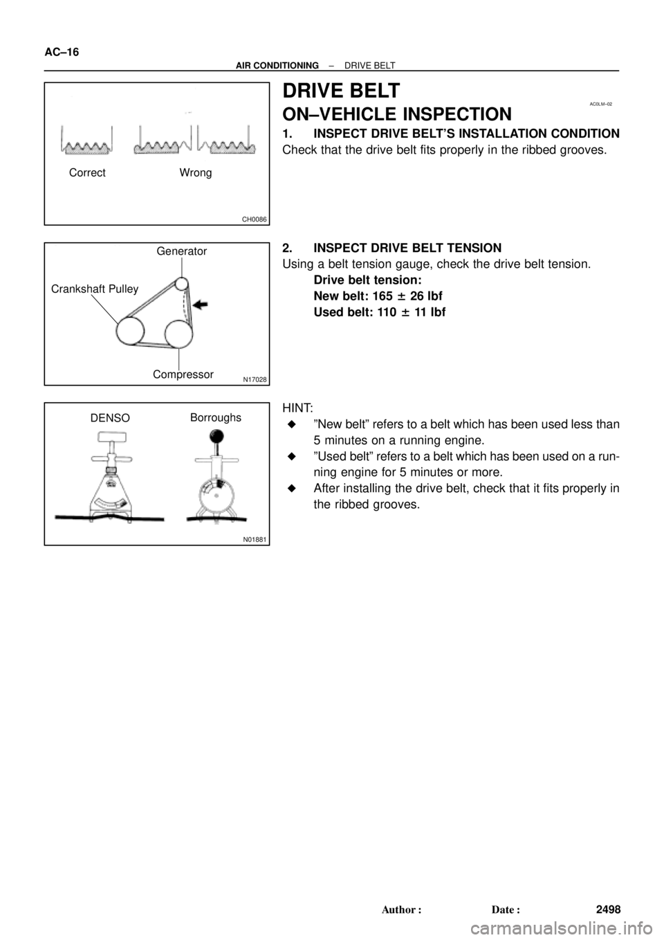
Correct Wrong
AC0LM±02
N17028
Generator
Crankshaft Pulley
Compressor
N01881
DENSOBorroughs AC±16
± AIR CONDITIONINGDRIVE BELT
2498 Author�: Date�:
DRIVE BELT
ON±VEHICLE INSPECTION
1. INSPECT DRIVE BELT'S INSTALLATION CONDITION
Check that the drive belt fits properly in the ribbed grooves.
2. INSPECT DRIVE BELT TENSION
Using a belt tension gauge, check the drive belt tension.
Drive belt tension:
New belt: 165 ± 26 lbf
Used belt: 110 ± 11 lbf
HINT:
�ºNew beltº refers to a belt which has been used less than
5 minutes on a running engine.
�ºUsed beltº refers to a belt which has been used on a run-
ning engine for 5 minutes or more.
�After installing the drive belt, check that it fits properly in
the ribbed grooves.
Page 1782 of 4770
Q10066
AX±24
± AUTOMATIC TRANSAXLE (A140E)AUTOMATIC TRANSAXLE UNIT
1917 Author�: Date�:
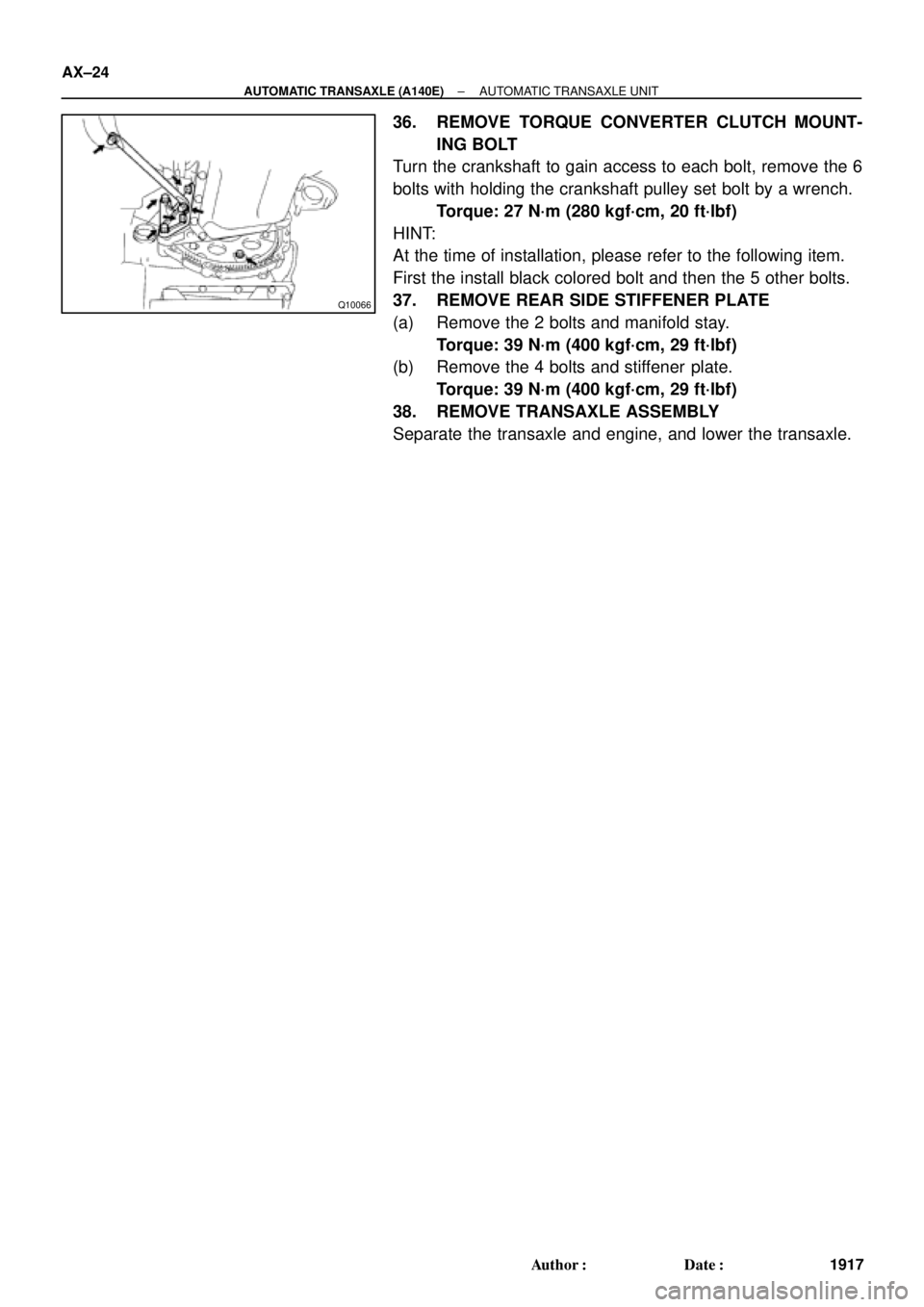
36. REMOVE TORQUE CONVERTER CLUTCH MOUNT-
ING BOLT
Turn the crankshaft to gain access to each bolt, remove the 6
bolts with holding the crankshaft pulley set bolt by a wrench.
Torque: 27 N´m (280 kgf´cm, 20 ft´lbf)
HINT:
At the time of installation, please refer to the following item.
First the install black colored bolt and then the 5 other bolts.
37. REMOVE REAR SIDE STIFFENER PLATE
(a) Remove the 2 bolts and manifold stay.
Torque: 39 N´m (400 kgf´cm, 29 ft´lbf)
(b) Remove the 4 bolts and stiffener plate.
Torque: 39 N´m (400 kgf´cm, 29 ft´lbf)
38. REMOVE TRANSAXLE ASSEMBLY
Separate the transaxle and engine, and lower the transaxle.
Page 1956 of 4770
AUTOMATIC TRANSAXLE UNIT
1948 Author�: Date�:
(d) Remove the 6 bolts and 4 nuts.
Torque:
19 mm head bo")
Q10172
Front
Q10064
Rear
Q04660
Q10036
Z14284
Left and lower AX±28
± AUTOMATIC TRANSAXLE (A541E)AUTOMATIC TRANSAXLE UNIT
1948 Author�: Date�:
(d) Remove the 6 bolts and 4 nuts.
Torque:
19 mm head bolt: 181 N´m (1,850 kgf´cm, 134 ft´lbf)
14 mm head bolt: 32 N´m (330 kgf´cm, 24 ft´lbf)
Nut: 36 N´m (370 kgf´cm, 27 ft´lbf)
(e) Remove the front frame assembly.
33. SUPPORT TRANSAXLE WITH A TRANSMISSION
JACK
34. REMOVE TORQUE CONVERTER CLUTCH MOUNT-
ING BOLTS
Turn the crankshaft to gain access to each bolt, remove the 6
bolts with holding the crankshaft pulley bolt by a wrench.
Torque: 41 N´m (420 kgf´cm, 30 ft´lbf)
HINT:
At the time of installation, please refer to the following item.
First install black colored bolt and then the 5 other bolts.
35. REMOVE EXHAUST MANIFOLD PLATE
(a) Remove the bolt, nut and exhaust manifold plate.
Torque:
Except California: 20 N´m (200 kgf´cm, 15 ft´lbf)
California: 34 N´m (350 kgf´cm, 25 ft´lbf)
36. REMOVE 3 LOWER TRANSAXLE±TO±ENGINE
BOLTS
Torque: 46 N´m (470 kgf´cm, 34 ft´lbf)
37. REMOVE TRANSAXLE ASSEMBLY
Separate the transaxle and engine, and lower the transaxle.
Page 2352 of 4770
S05939
No.2 Timing Belt
Cover
No.1 Timing Belt
Cover
Crankshaft
Pulley
No.2 Idler Pulley
Generator Drive Belt
Adjusting Bar
Wire Clamp
Crankshaft Position Sensor
Connector* Gasket
No.1 Idler Pulley
Tension Spring
� O±Ring
Water PumpWater PumpTiming Belt
Timing Belt Guide
Lower
Radiator
Hose Water Pump and
Water Pump Cover
Assembly High±Tension Cord Generator Wire
� Gasket Wire Clamp
Wire Clamp
Wire ClampWire Clamp Wire
Clamp
* GasketGenerator Connector
Generator
Spark Plug
� O±Ring
� Gasket
N´m (kgf´cm, ft´lbf): Specified torque
� Non±reusable part
108 (1,100, 80)18 (180,13)
42 (425,31)
42 (425,31)
* Replace only if damagedCover CO±4
± COOLING (5S±FE)WATER PUMP
1578 Author�: Date�:
Page 2353 of 4770
CO069±04
S05599
S05924
S05963
1
2
3
± COOLING (5S±FE)WATER PUMP
CO±5
1579 Author�: Date�:
REMOVAL
1. DRAIN ENGINE COOLANT
2. REMOVE TIMING BELT (See page EM±17)
3. DISCONNECT LOWER RADIATOR HOSE FROM WA-
TER OUTLET
4. REMOVE TIMING BELT TENSION SPRING
Loosen the No.1 idler pulley bolt, and remove the tension
spring.
5. REMOVE NO.2 IDLER PULLEY
Remove the bolt and idler pulley.
6. w/ Oil Cooler:
REMOVE A/C COMPRESSOR (See page EM±69)
7. REMOVE GENERATOR DRIVE BELT ADJUSTING
BAR
(a) Disconnect the engine wire clamp from the adjusting bar.
(b) Disconnect the crankshaft position sensor connector
from the bracket on the adjusting bar.
(c) Remove the bolt and adjusting bar.
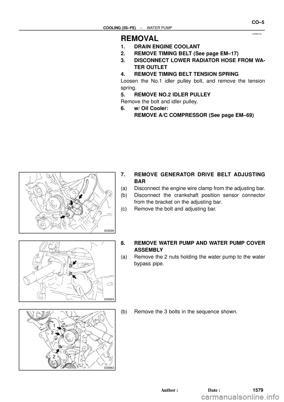
8. REMOVE WATER PUMP AND WATER PUMP COVER
ASSEMBLY
(a) Remove the 2 nuts holding the water pump to the water
bypass pipe.
(b) Remove the 3 bolts in the sequence shown.
Page 2356 of 4770
WATER PUMP
1582 Author�: Date�:
INSTALLATION
1. INSTALL WATER PUMP TO WATER PUMP COVER
Install a new gasket and the")
CO06B±03
N00918
S06015
Connect
Z19283
1
3
2
S05924
S05599
CO±8
± COOLING (5S±FE)WATER PUMP
1582 Author�: Date�:
INSTALLATION
1. INSTALL WATER PUMP TO WATER PUMP COVER
Install a new gasket and the water pump with the 3 bolts.
Torque: 8.8 N´m (90 kgf´cm, 78 in.´lbf)
2. INSTALL WATER PUMP AND WATER PUMP COVER
ASSEMBLY
(a) Install new O±ring and gasket to water pump cover.
(b) Install a new O±ring to the water bypass pipe.
(c) Apply soapy water to the O±ring on the water bypass
pipe.
(d) Connect the water pump cover to the water bypass pipe.
Do not install the nuts yet.
(e) Install the water pump with the 3 bolts. Tighten the bolts
in the sequence shown.
Torque: 8.8 N´m (90 kgf´cm, 78 in.´lbf)
(f) Install the 2 nuts holding the water pump cover to the wa-
ter bypass pipe.
Torque: 9.3 N´m (95 kgf´cm, 82 in.´lbf)
3. INSTALL GENERATOR DRIVE BELT ADJUSTING BAR
(a) Install the adjusting bar with the bolt.
Torque: 22 N´m (224 kgf´cm, 16 ft´lbf)
(b) Install the engine wire clamp to the adjusting bar.
(c) Install the crankshaft position sensor connector to the
bracket on the adjusting bar.
4. w/ Oil Cooler:
INSTALL A/C COMPRESSOR (See page EM±75)
5. INSTALL NO.2 IDLER PULLEY (See page EM±23)
Page 2386 of 4770
B06388
No.2 Timing Belt CoverTiming Belt
Gasket
Timing Belt Guide
No.2 Generator
Bracket RH Engine Mounting Bracket
Crankshaft
PulleyGasket
Engine Wire Protector
RH Camshaft Timing PulleyNo.2 Idler Pulley
Dust Boot
Timing Belt Tensioner
� Non±reusable part
*For use with SSTNo.1 Timing Belt Cover
LH Camshaft
Timing Pulley
N´m (kgf´cm, ft´lbf) : Specified torque
28 (290, 21)
215 (2,200, 159)
125 (1,300, 94)*88 (900, 65)
43 (440, 32)
27 (280, 20)
125 (1,300, 94)
CO±4
± COOLING (1MZ±FE)WATER PUMP
1612 Author�: Date�: