Page 3413 of 4770
S05579
SST
S05575
SST
± ENGINE MECHANICAL (5S±FE)TIMING BELT
EM±21
1193 Author�: Date�:
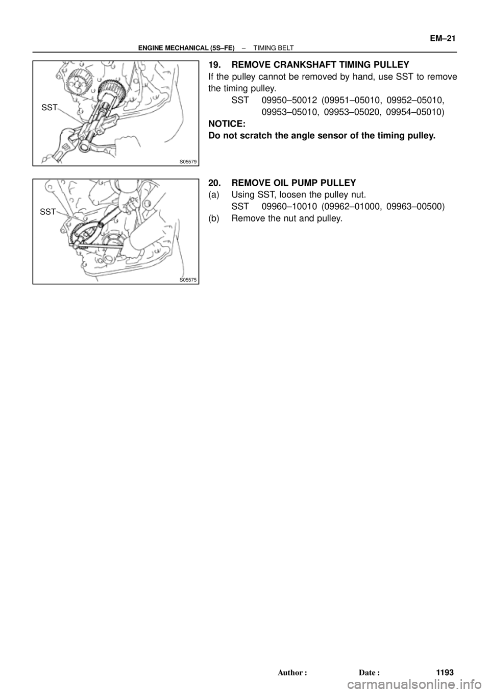
19. REMOVE CRANKSHAFT TIMING PULLEY
If the pulley cannot be removed by hand, use SST to remove
the timing pulley.
SST 09950±50012 (09951±05010, 09952±05010,
09953±05010, 09953±05020, 09954±05010)
NOTICE:
Do not scratch the angle sensor of the timing pulley.
20. REMOVE OIL PUMP PULLEY
(a) Using SST, loosen the pulley nut.
SST 09960±10010 (09962±01000, 09963±00500)
(b) Remove the nut and pulley.
Page 3415 of 4770
TIMING BELT
EM±23
1195 Author�: Date�:
INSTALLATION
1. INSTALL OIL PUMP PULLEY
(")
EM086±04
S05576
SST
S05577
Angle
Sensor
Inward
S05571
35 mm
S05616
42 mm
S05926
Pry
Move
± ENGINE MECHANICAL (5S±FE)TIMING BELT
EM±23
1195 Author�: Date�:
INSTALLATION
1. INSTALL OIL PUMP PULLEY
(a) Align the cutouts of the pulley and shaft, and slide on the
pulley.
(b) Using SST, install the pulley nut.
SST 09960±10010 (09962±01000, 09963±00500)
Torque: 24 N´m (245 kgf´cm, 18 ft´lbf)
2. INSTALL CRANKSHAFT TIMING PULLEY
(a) Align the timing pulley set key with the key groove of the
pulley.
(b) Slide on the timing pulley, facing the angle sensor inward.
NOTICE:
Do not scratch the angle sensor of the timing pulley.
3. INSTALL NO.2 IDLER PULLEY
(a) Install the pulley with the bolt.
Torque: 42 N´m (425 kgf´cm, 31 ft´lbf)
HINT:
Use the 35 mm (1.38 in.) long bolt.
(b) Check that the idler pulley moves smoothly.
4. TEMPORARILY INSTALL NO.1 IDLER PULLEY AND
TENSION SPRING
(a) Align the bracket pin hole with the pivot pin.
(b) Install the pulley with the bolt. Do not tighten the bolt yet.
HINT:
Use the 42 mm (1.65 in.) long bolt.
(c) Install the tension spring.
(d) Pry the pulley toward the left as far as it will go, and tighten
the bolt.
(e) Check that the idler pulley moves smoothly.
Page 3416 of 4770
 EM±24
± ENGINE MECHANICAL (5S±FE)TIMING BELT
1196 Author�: Date�:
5. TEMPORARILY INSTALL TIMING BELT
NOTICE:
The engine should be cold.
(a) Us")
S05574
S05944
S05578
P25230Length = 660 mm (25.98 in.) EM±24
± ENGINE MECHANICAL (5S±FE)TIMING BELT
1196 Author�: Date�:
5. TEMPORARILY INSTALL TIMING BELT
NOTICE:
The engine should be cold.
(a) Using the crankshaft pulley bolt, turn the crankshaft and
align the timing marks of the crankshaft timing pulley and
oil pump body.
(b) Remove any oil or water on the crankshaft pulley, oil
pump pulley, water pump pulley, No.1 idler pulley and
No.2 idler pulley, and keep them clean.
(c) Install the timing belt on the crankshaft timing pulley, oil
pump pulley, No.1 idler pulley, water pump pulley and
No.2 idler pulley.
HINT:
When re±using timing belt:
Align the points marked during removal, and install the belt with
the arrow pointing in the direction of engine revolution.
6. INSTALL TIMING BELT GUIDE
Install the guide, facing the cup side outward.
7. INSTALL NO.1 TIMING BELT COVER
(a) Check that the timing belt cover gasket has no cracks or
peeling, etc.
If the gasket has cracks or peeling, etc., replace it using these
steps:
(1) Using a screwdriver and gasket scraper, remove all
the old gasket material.
(2) Thoroughly clean all components to remove all the
loose material.
(3) Remove the backing paper from a new gasket and
install the gasket evenly to the part of the timing belt
cover shaded black in the illustration.
(4) After installing the gasket, press down on it so that
the adhesive firmly sticks to the timing belt cover.
Page 3417 of 4770
TIMING BELT
EM±25
1197 Author�: Date�:
(b) Install the timing belt cover with the 4 bolts.
(c) Install the")
A02591
S05588
SSTSST
S05592
SST
SST
Fulcrum
Length
S05587
Turn
± ENGINE MECHANICAL (5S±FE)TIMING BELT
EM±25
1197 Author�: Date�:
(b) Install the timing belt cover with the 4 bolts.
(c) Install the clamp of the crankshaft position sensor wire to
the timing belt cover.
(d) Install the crankshaft position sensor wire to the clamp on
the timing belt cover.
8. INSTALL CRANKSHAFT PULLEY
(a) Align the pulley set key with the key groove of the pulley,
and slide on the pulley.
(b) Using SST (and bolt), install the pulley bolt.
SST 09213±54015 (91651±60855),09330±00021
Torque: 108 N´m (1,100 kgf´cm, 80 ft´lbf)
HINT:
Either of 2 types of pulley may be used, each with its own bolt
size, type A (91651±60855) and type B
(part No. 91121±40665).
9. INSTALL CAMSHAFT TIMING PULLEY
(a) Align the camshaft knock pin with the knock pin groove of
the pulley, and slide on the timing pulley.
(b) Using SST, install the pulley bolt.
SST 09249±63010, 09960±10010 (09962±01000,
09963±01000)
Torque:
54 N´m (550 kgf´cm, 40 ft´lbf)
37 N´m (380 kgf´cm, 27 ft´lbf) for use with SST
HINT:
Use a torque wrench with a fulcrum length of 340 mm (13.39
in.).
10. SET NO.1 CYLINDER TO TDC/COMPRESSION
(a) Turn the crankshaft pulley, and align its groove with timing
mark º0º of the No.1 timing belt cover.
Page 3418 of 4770
S05594
SST
A02592
S05582
S05931
S05581
Loosen EM±26
± ENGINE MECHANICAL (5S±FE)TIMING BELT
1198 Author�: Date�:
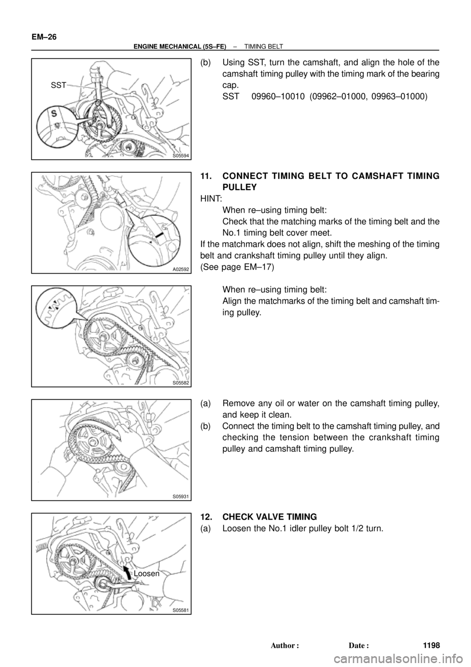
(b) Using SST, turn the camshaft, and align the hole of the
camshaft timing pulley with the timing mark of the bearing
cap.
SST 09960±10010 (09962±01000, 09963±01000)
11. CONNECT TIMING BELT TO CAMSHAFT TIMING
PULLEY
HINT:
�When re±using timing belt:
Check that the matching marks of the timing belt and the
No.1 timing belt cover meet.
If the matchmark does not align, shift the meshing of the timing
belt and crankshaft timing pulley until they align.
(See page EM±17)
�When re±using timing belt:
Align the matchmarks of the timing belt and camshaft tim-
ing pulley.
(a) Remove any oil or water on the camshaft timing pulley,
and keep it clean.
(b) Connect the timing belt to the camshaft timing pulley, and
checking the tension between the crankshaft timing
pulley and camshaft timing pulley.
12. CHECK VALVE TIMING
(a) Loosen the No.1 idler pulley bolt 1/2 turn.
Page 3419 of 4770

Length = 230 mm (9.06 in.)
± ENGINE MECHANICAL (5S±FE)TIMING BELT
EM±27
1199 Author�: Date�:
(b) Slowly turn the crankshaft")
S05587
Turn
S05598
S05586
Turn
S05585
S01710
Length = 735 mm (28.94 in.)
Length = 230 mm (9.06 in.)
± ENGINE MECHANICAL (5S±FE)TIMING BELT
EM±27
1199 Author�: Date�:
(b) Slowly turn the crankshaft pulley 2 revolutions TDC to
TDC.
NOTICE:
Always turn the crankshaft pulley clockwise.
(c) Check that each pulley aligns with the timing marks as
shown in the illustration.
If the timing marks do not align, remove the timing belt and rein-
stall it.
(d) Slowly turn the crankshaft pulley 1 and 7/8 revolutions,
and align its groove with the mark at 45° BTDC (for No.1
cylinder) of the No.1 timing belt cover.
NOTICE:
Always turn the crankshaft pulley clockwise.
(e) Tighten the mounting bolt of the No.1 idler pulley.
Torque: 42 N´m (425 kgf´cm, 31 ft´lbf)
13. INSTALL NO.2 TIMING BELT COVER
(a) Check that the timing belt cover gaskets have no cracks
or peeling, etc.
If the gasket has cracks or peeling, etc., replace it using these
steps:
(1) Using a screwdriver and gasket scraper, remove all
the old gasket material.
(2) Thoroughly clean all components to remove all the
loose material.
Page 3465 of 4770
ENGINE UNIT
EM±73
1245 Author�: Date�:
30. A/T:
REMOVE STARTER (See page ST±5)
31. DISCONNECT CONNECTORS
(a) Disconne")
S05526
TMMK
Made
TMC
Made
A02198
S05530
S05529
Turn
± ENGINE MECHANICAL (5S±FE)ENGINE UNIT
EM±73
1245 Author�: Date�:
30. A/T:
REMOVE STARTER (See page ST±5)
31. DISCONNECT CONNECTORS
(a) Disconnect the VSS connector.
(b) M/T:
Disconnect the back±up light switch connector.
(c) A/T:
Disconnect the PNP switch connector.
(d) A/T:
Disconnect the 2 solenoid connectors.
32. REMOVE NO.1 EXHAUST MANIFOLD STAY
Remove the 2 bolts and manifold stay.
33. REMOVE NO.2 EXHAUST MANIFOLD STAY AND LH
STIFFENER PLATE
(a) TMC Made:
Remove the 2 nuts and manifold stay.
(b) TMMK Made:
Remove the bolt, nut and manifold stay.
(c) Remove the 2 bolts and stiffener plate.
34. REMOVE INTAKE MANIFOLD STAY
Remove the 2 bolts and intake manifold stay.
35. REMOVE RH STIFFENER PLATE
Remove the 4 bolts and stiffener plate.
36. REMOVE EXHAUST PIPE BRACKET, OIL PAN INSU-
LATOR AND NO.2 REAR END PLATE
(a) Remove the 2 bolts and exhaust pipe bracket.
(b) Remove the 2 bolts, oil pan insulator and rear end plate.
37. A/T:
REMOVE TORQUE CONVERTER CLUTCH BOLTS
(a) Turn the crankshaft pulley bolt to gain access to each bolt.
(b) Hold the crankshaft pulley bolt with a wrench, and remove
the 6 bolts.
Page 3468 of 4770
ENGINE UNIT
1248 Author�: Date�:
7. A/T:
INSTALL TORQUE CONVERTER CLUTCH BOLTS
(a) Apply a")
Z19014Turn
Black
Colored
Bolt A/T
S05530
A02198
S05526
TMC
Made
TMMK
Made
EM±76
± ENGINE MECHANICAL (5S±FE)ENGINE UNIT
1248 Author�: Date�:
7. A/T:
INSTALL TORQUE CONVERTER CLUTCH BOLTS
(a) Apply adhesive to 2 or 3 threads of the bolt end.
Adhesive:
Part No. 08833±00070, THREE BOND 1324 or equiva-
lent
(b) Hold the crankshaft pulley bolt with a wrench, and install
the 6 bolts evenly.
Torque: 27 N´m (280 kgf´cm, 20 ft´lbf)
HINT:
First tighten the black colored bolt, install the other bolts.
8. INSTALL NO.2 REAR END PLATE, OIL PAN INSULA-
TOR AND EXHAUST PIPE BRACKET
(a) Install the oil pan insulator to the rear end plate.
(b) Install the rear end plate and exhaust pipe bracket with
the 4 bolts.
Torque:
9.3 N´m (95 kgf´cm, 82 in.´lbf) for 10 mm head
19 N´m (195 kgf´cm, 14 ft´lbf) for 12 mm head
9. INSTALL RH STIFFENER PLATE
Install the stiffener plate with the 4 bolts.
Torque: 39 N´m (398 kgf´cm, 29 ft´lbf)
10. INSTALL INTAKE MANIFOLD STAY
Install the manifold stay with the 2 bolts.
Torque: 39 N´m (398 kgf´cm, 29 ft´lbf)
11. INSTALL LH STIFFENER PLATE AND NO.2 EXHAUST
MANIFOLD STAY
(a) TMC Made:
Temporarily install the stiffener plate and manifold stay
with the 2 bolts and 2 nuts.
(b) TMMK Made:
Temporarily install the stiffener plate and manifold stay
with the 3 bolts and nut.
(c) Tighten the 2 bolts holding the stiffener plate to the trans-
axle.