Page 3527 of 4770
TIMING BELT
EM±21
1307 Author�: Date�:
INSTALLATION
1. INSTALL CRANKSHAFT TIMING PULLEY
(a")
EM0YO±01
A05060
Inward
Sensor
A01802
10 mm
Hexagon
Wrench
Plate Washer
A05055
± ENGINE MECHANICAL (1MZ±FE)TIMING BELT
EM±21
1307 Author�: Date�:
INSTALLATION
1. INSTALL CRANKSHAFT TIMING PULLEY
(a) Align the pulley set key with the key groove of the timing
pulley, and slide on the timing pulley.
(b) Install the timing pulley, facing the sensor side inward.
NOTICE:
Do not scratch the sensor part of the crankshaft timing
pulley.
(c) Install the timing belt plate with the bolt.
Torque: 8 N´m (80 kgf´cm, 69 in.´lbf)
2. INSTALL NO.1 IDLER PULLEY
Adhesive: Part No. 08833±00080, THREE BOND 1344,
LOCTITE 242 or equivalent
(a) Using a 10 mm hexagon wrench, install the plate washer
and idler pulley with the pivot bolt.
Torque: 34 N´m (350 kgf´cm, 25 ft´lbf)
(b) Check that the pulley bracket moves smoothly.
3. INSTALL NO.2 IDLER PULLEY
(a) Install the idler pulley with the bolt.
Torque: 43 N´m (440 kgf´cm, 32 ft´lbf)
(b) Check that the idler pulley moves smoothly.
4. INSTALL RH CAMSHAFT TIMING PULLEY
(a) Face the flange side of the timing pulley outward.
(b) Align the knock pin on the camshaft with the knock pin
groove of the timing pulley, and slide on the timing pulley.
Page 3528 of 4770
TIMING BELT
1308 Author�: Date�:
(c) Using SST, install the pulley bolt.
SST 09249±63010, 09960±1")
P20069
Fulcrum
Length
SSTSST RH
P12762
SST LH
P18811
A05063
SST
EM±22
± ENGINE MECHANICAL (1MZ±FE)TIMING BELT
1308 Author�: Date�:
(c) Using SST, install the pulley bolt.
SST 09249±63010, 09960±10010 (09962±01000,
09963±01000)
Torque: 88 N´m (900 kgf´cm, 65 ft´lbf)
HINT:
Use a torque wrench with a fulcrum length of 340 mm (13.39
in.).
5. INSTALL LH CAMSHAFT TIMING PULLEY
(a) Face the flange side of the timing pulley inward.
(b) Align the knock pin on the camshaft with the knock pin
groove of the timing pulley, and slide on the timing pulley.
(c) Using SST, install the pulley bolt.
SST 09960±10010 (09962±01000, 09963±01000)
Torque: 125 N´m (1,300 kgf´cm, 94 ft´lbf)
6. SET NO.1 CYLINDER TO TDC/COMPRESSION
(a) Crankshaft Timing Pulley Position:
Temporarily install the crankshaft pulley bolt to the crank-
shaft.
(b) Crankshaft Timing Pulley Position:
Turn the crankshaft, and align the timing marks of the
crankshaft timing pulley and oil pump body.
(c) Camshaft Timing Pulley Positions:
Using SST, turn the camshaft pulley, align the timing
marks of the timing pulley and No.3 timing belt cover.
SST 09960±10010 (09962±01000, 09963±01000)
Page 3529 of 4770
TIMING BELT
EM±23
1309 Author�: Date�:
7. INSTALL TIMING BELT
NOTICE:
The")
A02338
5th4th3rd
2nd
6th
1st
A05064
1.27 mm
Hexagon
Wrench
A05065
A05066
1.27 mm
Hexagon
Wrench
± ENGINE MECHANICAL (1MZ±FE)TIMING BELT
EM±23
1309 Author�: Date�:
7. INSTALL TIMING BELT
NOTICE:
The engine should be cold.
(a) Remove any oil or water on the pulleys, and keep them
clean.
NOTICE:
Only wipe the pulleys; do not use any cleansing agent.
(b) Face the front mark on the timing belt forward.
(c) Align the installation mark on the timing belt with the tim-
ing mark of the crankshaft timing pulley.
(d) Align the installation marks on the timing belt with the tim-
ing marks of the camshaft timing pulleys.
(e) Install the timing belt in this order:
1st: Crankshaft timing pulley
2nd: Water pump pulley
3rd: LH camshaft timing pulley
4th: No.2 idler pulley
5th: RH camshaft timing pulley
6th: No.1 idler pulley
8. SET TIMING BELT TENSIONER
(a) Using a press, slowly press in the push rod using 981 ±
9,807 N (100 ± 1,000 kgf, 200 ± 2,205 lbf) of pressure.
(b) Align the holes of the push rod and housing, pass a 1.27
mm hexagon wrench through the holes to keep the set-
ting position of the push rod.
(c) Release the press.
(d) Install the dust boot to the tensioner.
9. INSTALL TIMING BELT TENSIONER
(a) Temporarily install the tensioner with the 2 bolts.
(b) Alternately tighten the 2 bolts.
Torque: 27 N´m (280 kgf´cm, 20 ft´lbf)
(c) Remove the 1.27 mm hexagon wrench from the tension-
er.
Page 3530 of 4770

P18815
EM±24
± ENGINE MECHANICAL (1MZ±FE)TIMING BELT
1310 Author�: Date�:
10. CHECK VALVE TIMING
(a) Slowly turn the crankshaft 2 revolutions, and")
P18808
A05052
P12983
Length = 1,410 mm (55.51 in.)
P18815
EM±24
± ENGINE MECHANICAL (1MZ±FE)TIMING BELT
1310 Author�: Date�:
10. CHECK VALVE TIMING
(a) Slowly turn the crankshaft 2 revolutions, and align the tim-
ing marks of the crankshaft timing pulley and oil pump
body.
NOTICE:
Always turn the crankshaft clockwise.
(b) Check that the timing marks of the RH and LH timing pul-
leys with the timing marks of the No.3 timing belt cover as
shown in the illustration.
If the marks do not align, remove the timing belt and reinstall it.
(c) Remove the crankshaft pulley bolt.
11. INSTALL RH ENGINE MOUNTING BRACKET
Torque: 28 N´m (290 kgf´cm, 21 ft´lbf)
12. INSTALL NO.2 TIMING BELT COVER
(a) Check that the timing belt cover gasket has no cracks or
peeling, etc.
If the gasket has cracks or peeling, etc., replace it using these
steps:
�Using a screwdriver and gasket scraper, remove all
the old gasket material.
�Thoroughly clean all components to remove all the
loose material.
�Remove the backing paper from a new gasket and
install the gasket evenly to the part of the timing belt
cover shaded black in the illustration.
�After installing the gasket, press down on it so that
the adhesive firmly sticks to the timing belt cover.
(b) Install the timing belt cover with the 5 bolts.
Torque: 8.5 N´m (85 kgf´cm, 74 in.´lbf)
(c) Install the engine wire protector clamps to the No.3 timing
belt cover.
13. INSTALL TIMING BELT GUIDE
Install the timing belt guide, facing the cup side outward.
Page 3531 of 4770

Join
Line
Join
Line
Length = 460 mm
(18.11 in.)
A04693
SST
P18816
± ENGINE MECHANICAL (1MZ±FE)TIMING BELT
EM±25
1311 Author�: Date�:
14. INSTALL NO.1 TIMING BELT C")
P12982
Length = 240 mm (9.45 in.)
Join
Line
Join
Line
Length = 460 mm
(18.11 in.)
A04693
SST
P18816
± ENGINE MECHANICAL (1MZ±FE)TIMING BELT
EM±25
1311 Author�: Date�:
14. INSTALL NO.1 TIMING BELT COVER
(a) Check that the timing belt cover gaskets have cracks or
peeling, etc.
If the gasket has cracks or peeling, etc., replace it using these
steps:
�Using a screwdriver and gasket scraper, remove all
the old gasket material.
�Thoroughly clean all components to remove all the
loose material.
�Remove the backing paper from a new gasket and
install the gasket evenly to the part of the timing belt
cover shaded black in the illustration.
NOTICE:
When joining 2 gaskets, do not leave a gap between them.
Cut off any excess gasket.
�After installing the gasket, press down on it so that
the adhesive firmly sticks to the timing belt cover.
(b) Install the timing belt cover with the 4 bolts.
Torque: 8.5 N´m (85 kgf´cm, 74 in.´lbf)
15. INSTALL CRANKSHAFT PULLEY
(a) Align the pulley set key with the key groove of the pulley,
and slide on the pulley.
(b) Using SST, install the pulley bolt.
SST 09213±54015 (91651±60855), 09330±00021
Torque: 215 N´m (2,200 kgf´cm, 159 ft´lbf)
16. INSTALL NO.2 GENERATOR BRACKET
Install the generator bracket with the pivot bolt and nut. Do not
tighten the bolt yet.
Torque: (Nut): 28 N´m (290 kgf´cm, 21 ft´lbf)
17. INSTALL NO.2 RH ENGINE MOUNTING BRACKET,
ENGINE MOVING CONTROL ROD, NO.2 RH ENGINE
MOUNTING STAY (M/T) AND RH ENGINE MOUNTING
STAY (See page EM±76)
18. CONNECT GROUND STRAP CONNECTORS
19. CONNECT ENGINE COOLANT RESERVOIR HOSE TO
WATER OUTLET
20. INSTALL PS PUMP DRIVE BELT
21. INSTALL GENERATOR DRIVE BELT
(See page CH±16)
Page 3535 of 4770
A05070
Timing Belt
Gasket No.2 Timing Belt Cover
RH Engine Mounting Bracket
Crankshaft
Pulley No.1 Timing Belt Cover
Gasket
Engine Wire
Protector
No.2 Idler Pulley
RH Camshaft Timing Pulley
LH Camshaft
Timing Pulley
Timing Belt TensionerTiming Belt Guide
No.2 Generator
Bracket
Dust Boot
N´m (kgf´cm, ft´lbf) : Specified torque
* For use with SST� Non±reusable part
28 (290, 21)
215 (2,200, 159)
125 (1,300, 94)
*88 (900, 65)
27 (280, 20)
43 (440, 32)
125 (1,300, 94)
± ENGINE MECHANICAL (1MZ±FE)CYLINDER HEAD
EM±29
1315 Author�: Date�:
Page 3587 of 4770

No.2 Idler Pulley Bracket
Water Seal Plate
Engine Cool")
EM050±03
A06640
Knock Sensor Connector
Engine Wire Band
Engine WireKnock Sensor
No.2 ECT Switch Connector
Water Inlet Housing
(With Water Inlet)
No.2 Idler Pulley Bracket
Water Seal Plate
Engine Coolant
Drain Union
Oil Filter Union
Oil Filter � Gasket
EGR Cooler
� Gasket
Water Pump
� Crankshaft
Front Oil Seal
Crankshaft
Position Sensor
Connector� Oil Pressure Switch
Oil Pressure Switch
ConnectorA/C Compressor
Housing Bracket
No.1 Oil Pan
x 15 or 17 Oil Pump
� Gasket
� Gasket
Engine Wire
Generator
Drain Plugx 10No.2 Oil Pan Oil Strainer
� Non±reusable part
N´m (kgf´cm, ft´lbf) : Specified torque
Precoated part �
x 8
�
� O±Ring
x 9
9 (90, 78 in.´lbf)
8 (80, 69 in.´lbf)
10mm Head 7.8 (80, 69 in.´lbf)
12mm Head 19.5 (200,14)
39 (400, 29)
28 (290, 21)
14.5 (145, 10)
25 (250, 18)
10mm Head 8 (80, 69 in.´lbf)
12mm Head 19.5 (200,14)
8 (80, 69 in.´lbf)
8 (80, 69 in.´lbf)45 (460, 33)
8 (80, 69 in.´lbf)
or 0 or 0
± ENGINE MECHANICAL (1MZ±FE)CYLINDER BLOCK
EM±81
1367 Author�: Date�:
CYLINDER BLOCK
COMPONENTS
Page 3616 of 4770
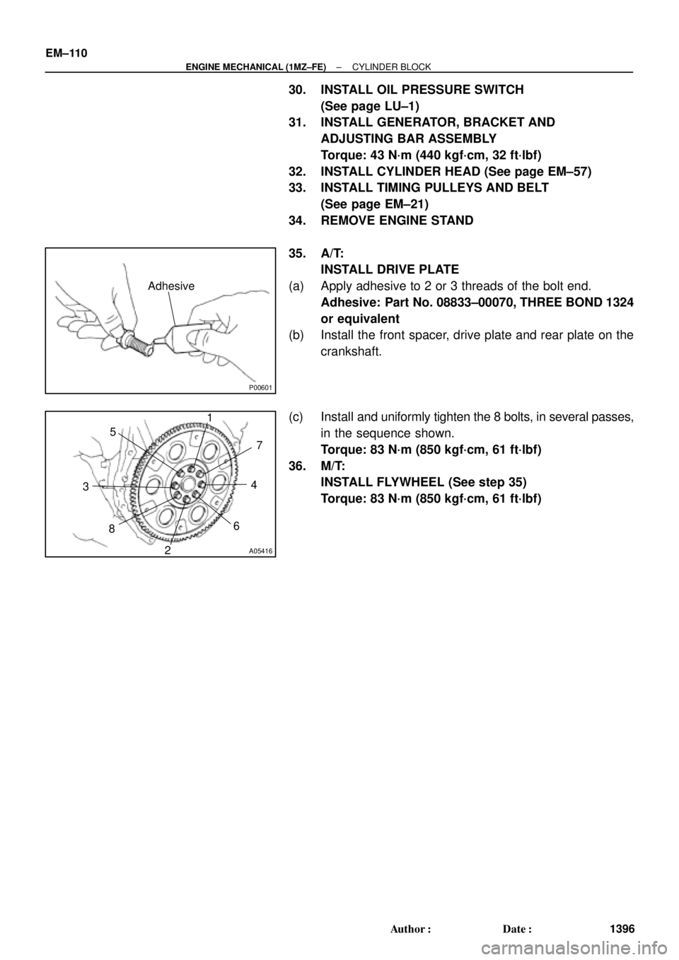
P00601
Adhesive
A05416
1
2 34 5
67
8
EM±110
± ENGINE MECHANICAL (1MZ±FE)CYLINDER BLOCK
1396 Author�: Date�:
30. INSTALL OIL PRESSURE SWITCH
(See page LU±1)
31. INSTALL GENERATOR, BRACKET AND
ADJUSTING BAR ASSEMBLY
Torque: 43 N´m (440 kgf´cm, 32 ft´lbf)
32. INSTALL CYLINDER HEAD (See page EM±57)
33. INSTALL TIMING PULLEYS AND BELT
(See page EM±21)
34. REMOVE ENGINE STAND
35. A/T:
INSTALL DRIVE PLATE
(a) Apply adhesive to 2 or 3 threads of the bolt end.
Adhesive: Part No. 08833±00070, THREE BOND 1324
or equivalent
(b) Install the front spacer, drive plate and rear plate on the
crankshaft.
(c) Install and uniformly tighten the 8 bolts, in several passes,
in the sequence shown.
Torque: 83 N´m (850 kgf´cm, 61 ft´lbf)
36. M/T:
INSTALL FLYWHEEL (See step 35)
Torque: 83 N´m (850 kgf´cm, 61 ft´lbf)