Page 2522 of 4770
DI±102
± DIAGNOSTICSENGINE (5S±FE)
337 Author�: Date�:
3 Inspect sensor installation and teeth of crankshaft timing pulley
(See pages IG±10 and EM±15).
NG Tighten the sensor. Replace crankshaft timing
pulley.
OK
Check and replace ECM (See page IN±31).
Page 2524 of 4770
DI±104
± DIAGNOSTICSENGINE (5S±FE)
339 Author�: Date�:
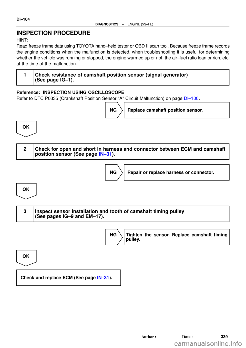
INSPECTION PROCEDURE
HINT:
Read freeze frame data using TOYOTA hand±held tester or OBD II scan tool. Because freeze frame records
the engine conditions when the malfunction is detected, when troubleshooting it is useful for determining
whether the vehicle was running or stopped, the engine warmed up or not, the air±fuel ratio lean or rich, etc.
at the time of the malfunction.
1 Check resistance of camshaft position sensor (signal generator)
(See page IG±1).
Reference: INSPECTION USING OSCILLOSCOPE
Refer to DTC P0335 (Crankshaft Position Sensor ºAº Circuit Malfunction) on page DI±100.
NG Replace camshaft position sensor.
OK
2 Check for open and short in harness and connector between ECM and camshaft
position sensor (See page IN±31).
NG Repair or replace harness or connector.
OK
3 Inspect sensor installation and tooth of camshaft timing pulley
(See pages IG±9 and EM±17).
NG Tighten the sensor. Replace camshaft timing
pulley.
OK
Check and replace ECM (See page IN±31).
Page 2709 of 4770
± DIAGNOSTICSENGINE (1MZ±FE)
DI±289
524 Author�: Date�:
3 Inspect sensor installation and teeth of crankshaft timing pulley.
NG Tighten the sensor.
Replace crankshaft timing pulley.
OK
Check and replace ECM
(See page IN±31).
Page 3396 of 4770
EM07Z±03
S05289
(c)
(d) (e)
S05590
Turn
P03443
1 11 122
33 EM±4
± ENGINE MECHANICAL (5S±FE)VALVE CLEARANCE
1176 Author�: Date�:
VALVE CLEARANCE
INSPECTION
HINT:
Inspect and adjust the valve clearance when the engine is cold.
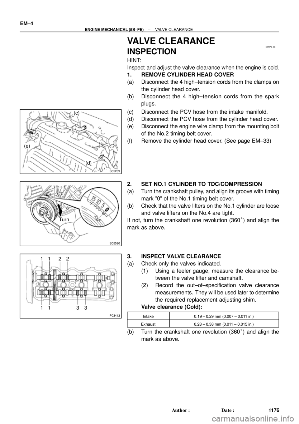
1. REMOVE CYLINDER HEAD COVER
(a) Disconnect the 4 high±tension cords from the clamps on
the cylinder head cover.
(b) Disconnect the 4 high±tension cords from the spark
plugs.
(c) Disconnect the PCV hose from the intake manifold.
(d) Disconnect the PCV hose from the cylinder head cover.
(e) Disconnect the engine wire clamp from the mounting bolt
of the No.2 timing belt cover.
(f) Remove the cylinder head cover. (See page EM±33)
2. SET NO.1 CYLINDER TO TDC/COMPRESSION
(a) Turn the crankshaft pulley, and align its groove with timing
mark º0º of the No.1 timing belt cover.
(b) Check that the valve lifters on the No.1 cylinder are loose
and valve lifters on the No.4 are tight.
If not, turn the crankshaft one revolution (360°) and align the
mark as above.
3. INSPECT VALVE CLEARANCE
(a) Check only the valves indicated.
(1) Using a feeler gauge, measure the clearance be-
tween the valve lifter and camshaft.
(2) Record the out±of±specification valve clearance
measurements. They will be used later to determine
the required replacement adjusting shim.
Valve clearance (Cold):
Intake0.19 ± 0.29 mm (0.007 ± 0.011 in.)
Exhaust0.28 ± 0.38 mm (0.011 ± 0.015 in.)
(b) Turn the crankshaft one revolution (360°) and align the
mark as above.
Page 3408 of 4770
S05937
No.2 Timing Belt
Cover
No.1 Timing Belt
Cover
Tension Spring Crankshaft
Pulley
Camshaft Timing Pulley
No.1 Idler Pulley
No.2 Idler Pulley
Oil Pump Pulley
Crankshaft Timing Pulley Wire ClampWire ClampWire ClampSpark Plug High±Tension CordTiming Belt Guide Timing Belt
*
1 Gasket Wire
ClampGenerator Wire
Generator Connector
Generator
Wire
Clamp
N´m (kgf´cm, ft´lbf)
*
2 For use with SST
42 (425, 31)
42 (425, 31)
24 (245, 18)18 (180, 13) 108 (1,100, 80)
54 (550, 40)
*
2
37 (380, 27)
: Specified torque*
1 Gasket
*
1
Replace only if damaged EM±16
± ENGINE MECHANICAL (5S±FE)TIMING BELT
1188 Author�: Date�:
Page 3410 of 4770
S05587
Turn
S05580
A02585
S05583
Pry
Move
S05593
SSTSST EM±18
± ENGINE MECHANICAL (5S±FE)TIMING BELT
1190 Author�: Date�:
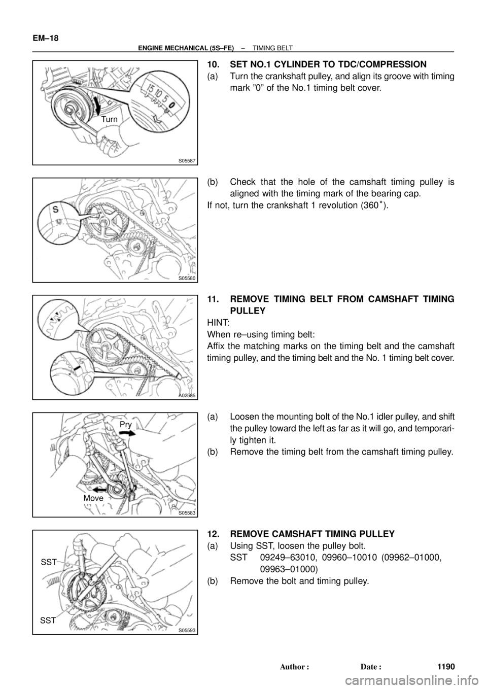
10. SET NO.1 CYLINDER TO TDC/COMPRESSION
(a) Turn the crankshaft pulley, and align its groove with timing
mark º0º of the No.1 timing belt cover.
(b) Check that the hole of the camshaft timing pulley is
aligned with the timing mark of the bearing cap.
If not, turn the crankshaft 1 revolution (360°).
11. REMOVE TIMING BELT FROM CAMSHAFT TIMING
PULLEY
HINT:
When re±using timing belt:
Affix the matching marks on the timing belt and the camshaft
timing pulley, and the timing belt and the No. 1 timing belt cover.
(a) Loosen the mounting bolt of the No.1 idler pulley, and shift
the pulley toward the left as far as it will go, and temporari-
ly tighten it.
(b) Remove the timing belt from the camshaft timing pulley.
12. REMOVE CAMSHAFT TIMING PULLEY
(a) Using SST, loosen the pulley bolt.
SST 09249±63010, 09960±10010 (09962±01000,
09963±01000)
(b) Remove the bolt and timing pulley.
Page 3411 of 4770
S05589
SST
A02586
A02587
Turn
Pull
A02588
Turn
Hold
A02589TurnPull
± ENGINE MECHANICAL (5S±FE)TIMING BELT
EM±19
1191 Author�: Date�:
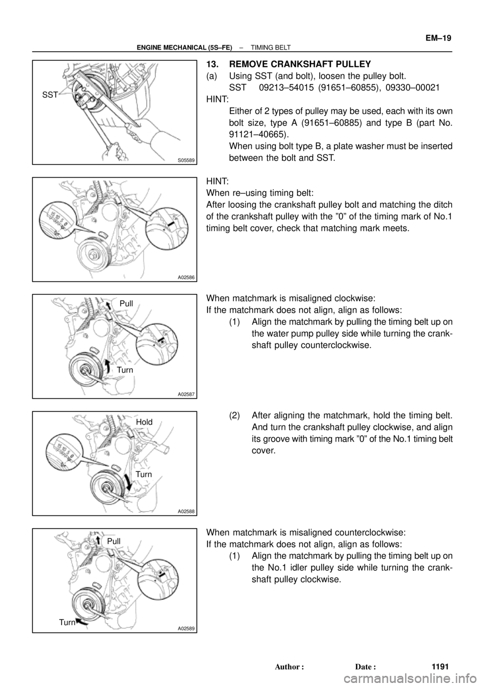
13. REMOVE CRANKSHAFT PULLEY
(a) Using SST (and bolt), loosen the pulley bolt.
SST 09213±54015 (91651±60855), 09330±00021
HINT:
�Either of 2 types of pulley may be used, each with its own
bolt size, type A (91651±60885) and type B (part No.
91121±40665).
�When using bolt type B, a plate washer must be inserted
between the bolt and SST.
HINT:
When re±using timing belt:
After loosing the crankshaft pulley bolt and matching the ditch
of the crankshaft pulley with the º0º of the timing mark of No.1
timing belt cover, check that matching mark meets.
When matchmark is misaligned clockwise:
If the matchmark does not align, align as follows:
(1) Align the matchmark by pulling the timing belt up on
the water pump pulley side while turning the crank-
shaft pulley counterclockwise.
(2) After aligning the matchmark, hold the timing belt.
And turn the crankshaft pulley clockwise, and align
its groove with timing mark º0º of the No.1 timing belt
cover.
When matchmark is misaligned counterclockwise:
If the matchmark does not align, align as follows:
(1) Align the matchmark by pulling the timing belt up on
the No.1 idler pulley side while turning the crank-
shaft pulley clockwise.
Page 3412 of 4770
A02590TurnHold
S05612
SST
S05591
S05944
S05614
EM±20
± ENGINE MECHANICAL (5S±FE)TIMING BELT
1192 Author�: Date�:
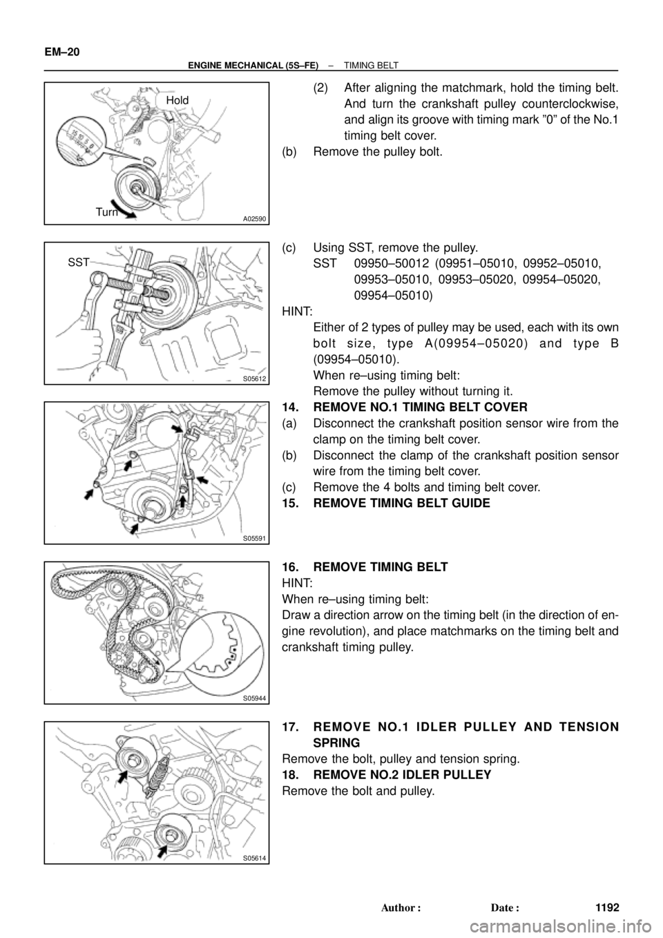
(2) After aligning the matchmark, hold the timing belt.
And turn the crankshaft pulley counterclockwise,
and align its groove with timing mark º0º of the No.1
timing belt cover.
(b) Remove the pulley bolt.
(c) Using SST, remove the pulley.
SST 09950±50012 (09951±05010, 09952±05010,
09953±05010, 09953±05020, 09954±05020,
09954±05010)
HINT:
�Either of 2 types of pulley may be used, each with its own
bolt size, type A(09954±05020) and type B
(09954±05010).
�When re±using timing belt:
Remove the pulley without turning it.
14. REMOVE NO.1 TIMING BELT COVER
(a) Disconnect the crankshaft position sensor wire from the
clamp on the timing belt cover.
(b) Disconnect the clamp of the crankshaft position sensor
wire from the timing belt cover.
(c) Remove the 4 bolts and timing belt cover.
15. REMOVE TIMING BELT GUIDE
16. REMOVE TIMING BELT
HINT:
When re±using timing belt:
Draw a direction arrow on the timing belt (in the direction of en-
gine revolution), and place matchmarks on the timing belt and
crankshaft timing pulley.
17. REMOVE NO.1 IDLER PULLEY AND TENSION
SPRING
Remove the bolt, pulley and tension spring.
18. REMOVE NO.2 IDLER PULLEY
Remove the bolt and pulley.