Page 2209 of 4770

BE0B0±06
BE4029
Tester Probe
Aluminum Foil
I00430
I00459
Matching
module
BE0150
Repair Point
Masking TapeBroken
Wire
± BODY ELECTRICALAUDIO SYSTEM
BE±115
2335 Author�: Date�:
INSPECTION
1. GLASS PRINTED ANTENNA INSPECTION PROCE-
DURE
NOTICE:
�When cleaning the glass, use soft dry cloth, and wipe
the glass in the direction of the wire.
Take care not to damage the wires.
�Do not use detergents or glass cleaners with abrasive
ingredients.
NOTICE:
In order not to damage the glass printed antenna, wrap up
the tip of the tester stick with aluminum foil as shown in the
illustration and check by holding the aluminum foil with a
finger.
By placing and moving the tester stick along the glass printed
antenna, check if continuity exists.
HINT:
Matching module is built in the bus bar of the glass printed an-
tenna (main terminal side) of CAMRY and no continuity exists
between the terminal and the antenna. Therefore, for the conti-
nuity checking of the glass printed antenna on the main anten-
na side of CAMRY, place one probe of the tester on the position
beside the bus bar (position shown in the illustration) and check
by making the other probe of the tester move along.
2. GLASS PRINTED ANTENNA REPAIR PROCEDURE
(a) Clean the broken wire tips with grease, wax and silicone
remover.
(b) Place the masking tape along both sides of the wire for
repair.
(c) Thoroughly mix the repair agent (Dupont paste No.
4817).
Page 2221 of 4770
BE0B3±06
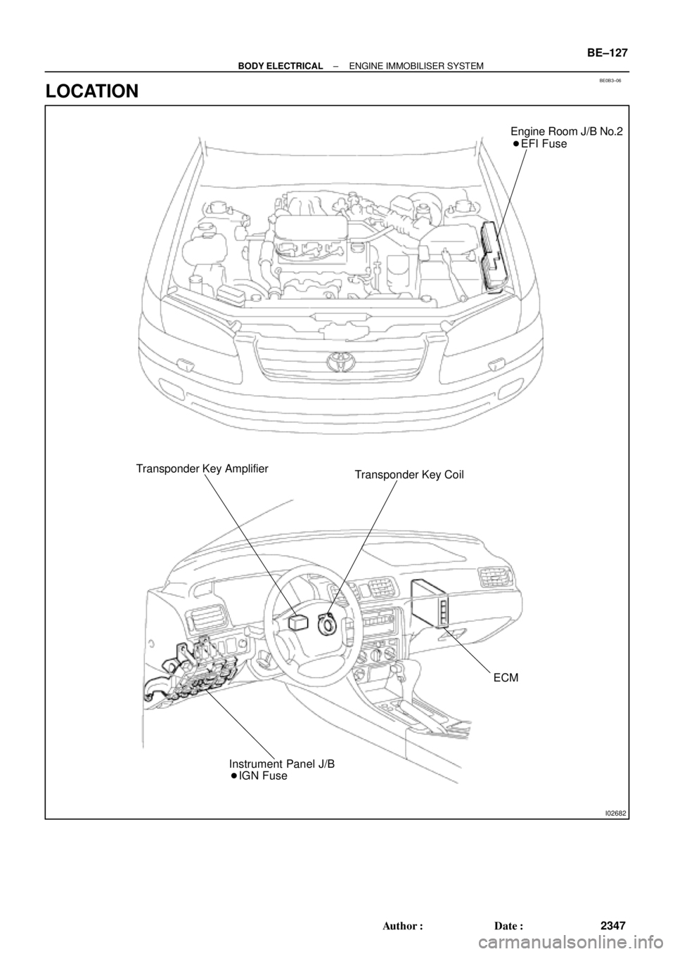
I02682
Engine Room J/B No.2
� EFI Fuse
Transponder Key Amplifier
Transponder Key Coil
ECM
� IGN Fuse Instrument Panel J/B
± BODY ELECTRICALENGINE IMMOBILISER SYSTEM
BE±127
2347 Author�: Date�:
LOCATION
Page 2222 of 4770
I03099
BE0B4±05
BE±128
± BODY ELECTRICALENGINE IMMOBILISER SYSTEM
2348 Author�: Date�:
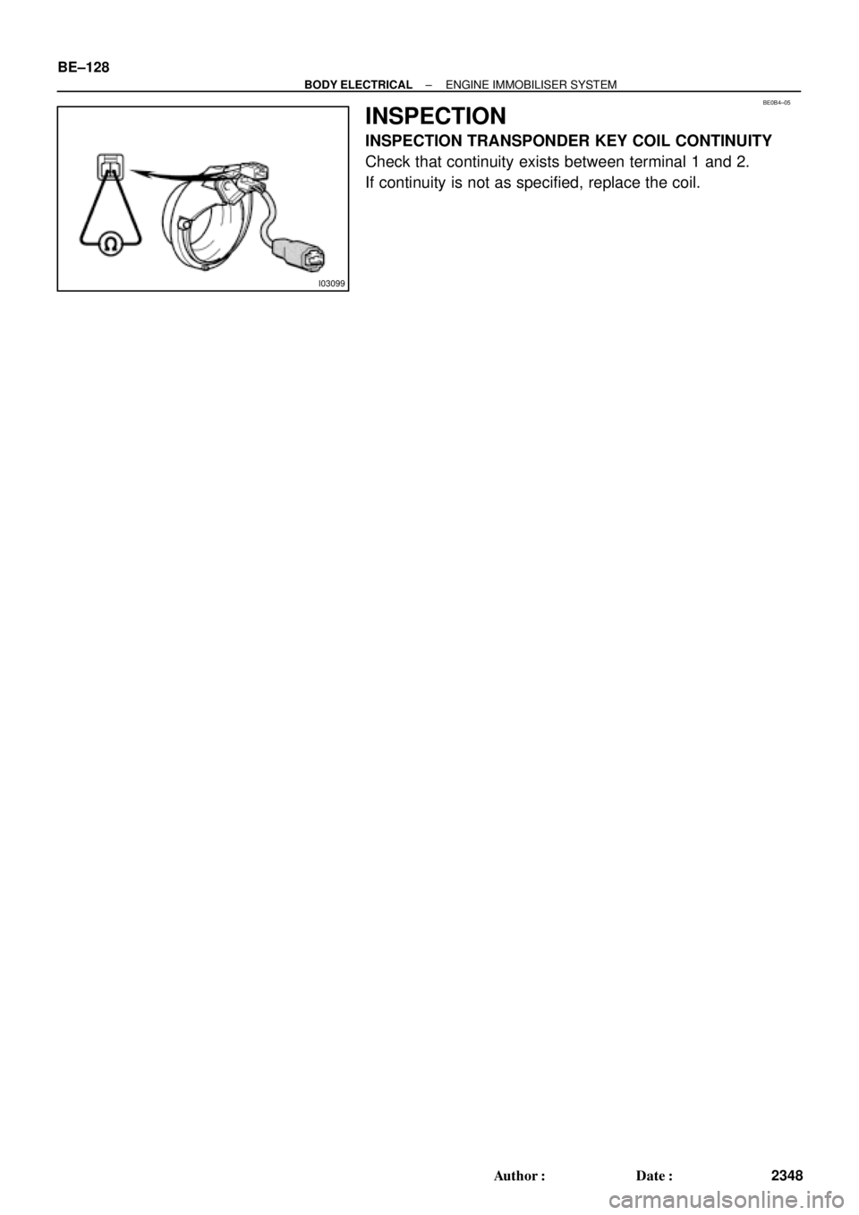
INSPECTION
INSPECTION TRANSPONDER KEY COIL CONTINUITY
Check that continuity exists between terminal 1 and 2.
If continuity is not as specified, replace the coil.
Page 2224 of 4770

BR0AA±03
BR±2
± BRAKETROUBLESHOOTING
2025 Author�: Date�:
TROUBLESHOOTING
PROBLEM SYMPTOMS TABLE
Use the table below to help you find the cause of the problem. The numbers indicate the priority of the likely
cause of the problem. Check each part in order. If necessary, replace these parts.
SymptomCAUSEPAGE
Low pedal or spongy pedal
1. Fluid leaks for brake system
2. Air in brake system
3. Piston seals (Worn or damaged)
4. Rear brake shoe clearance (Out of adjustment)
5. Master cylinder (Faulty)
6. Booster push rod (Out of adjustment)DI±536
BR±4
BR±24
BR±31
BR±39
BR±35
BR±9
BR±20
Brake drag
1. Brake pedal freeplay (Minimal)
2. Parking brake lever travel (Out of adjustment)
3. Parking brake wire (Sticking)
4. Rear brake shoe clearance (Out of adjustment)
5. Pad or lining (Cracked or distorted)
6. Piston (Stuck)
7. Piston (Frozen)
8. Anchor, return or tension spring (Faulty)
9. Booster push rod (Out of adjustment)
10.Vacuum leaks for booster system
11. Master cylinder (Faulty)BR±5
BR±8
BR±35
BR±21
BR±31
BR±36
BR±24
BR±31
BR±39
BR±24
BR±31
BR±39
BR±31
BR±45
BR±20
BR±18
BR±9
Brake pull
1. Piston (Stuck)
2. Pad or lining (Oily)
3. Piston (Frozen)
4. Disc (Scored)
5. Pad or lining (Cracked or distorted)BR±24
BR±31
BR±39
BR±21
BR±31
BR±36
BR±24
BR±31
BR±39
BR±24
BR±39
BR±21
BR±31
BR±36
Page 2225 of 4770
± BRAKETROUBLESHOOTING
BR±3
2026 Author�: Date�:
Hard pedal but brake inefficient
1. Fluid leaks for brake system
2. Air in brake system
3. Pad or lining (Worn)
4. Pad or lining (Cracked or distorted)
5. Rear brake shoe clearance (Out of adjustment)
6. Pad or lining (Oily)
7. Pad or lining (Glazed)
8. Disc (Scored)
9. Booster push rod (Out of adjustment)
10.Vacuum leaks for booster systemDI±536
BR±4
BR±21
BR±31
BR±36
BR±21
BR±31
BR±36
BR±35
BR±21
BR±31
BR±36
BR±21
BR±31
BR±36
BR±24
BR±39
BR±20
BR±18
Noise from brakes
1. Pad or lining (Cracked or distorted)
2. Installation bolt (Loose)
3. Disc (Scored)
4. Pad support plate (Loose)
5. Sliding pin (Worn)
6. Pad or lining (Dirty)
7. Pad or lining (Glazed)
8. Anchor, return or tension spring (Faulty)
9. Anti±squeal shim (Damaged)
10.Shoe hold±down spring (Damaged)BR±21
BR±31
BR±36
BR±24
BR±39
BR±24
BR±39
BR±21
BR±36
BR±24
BR±39
BR±21
BR±31
BR±36
BR±21
BR±31
BR±36
BR±31
BR±45
BR±21
BR±36
BR±31
BR±45
Page 2245 of 4770
 1MZ±FE engine:
Install a pad wear indicator plate on the inner pad.
(b) Apply disc brake grease to both sides of the inner anti±")
R00595
R02981
± BRAKEFRONT BRAKE PAD
BR±23
2046 Author�: Date�:
(a) 1MZ±FE engine:
Install a pad wear indicator plate on the inner pad.
(b) Apply disc brake grease to both sides of the inner anti±
squeal shims (See page BR±21).
(c) Install the 2 anti±squeal shims on each pad.
(d) Install inner pad with the pad wear indicator plate facing
upward.
(e) Install inner pad.
(f) Install outer pad.
NOTICE:
There should be no oil or grease adhering to the friction
surfaces of the pads or the disc.
(g) 5S±FE engine:
Install the 2 anti±squeal springs.
13. INSTALL CALIPER
(a) Draw out a small amount of brake fluid from the reservoir.
(b) Press in the piston with a hammer handle or similar imple-
ment.
HINT:
If the piston is difficult to push in, loosen the bleeder plug and
push in the piston while letting some brake fluid escape.
(c) Install the caliper.
(d) 5S±FE engine:
Hold the sliding pin and torque the installation bolt.
(e) 1MZ±FE engine:
Install the installation bolt.
Torque: 34 N´m (350 kgf´cm, 25 ft´lbf)
(f) Install the flexible hose and bolt to the bracket.
Torque: 29 N´m (300 kgf´cm, 21 ft´lbf)
14. INSTALL FRONT WHEEL
Torque: 103 N´m (1,050 kgf´cm, 76 ft´lbf)
15. DEPRESS BRAKE PEDAL SEVERAL TIMES
16. CHECK THAT FLUID LEVEL IS AT MAX LINE
Page 2255 of 4770
 Using SST, remove the shoe hold±down spring, 2 cups
and pin.
SST 09718±00010
(b) Using a scre")
R00248
SST
Z03633
BR1540
SST
± BRAKEREAR DRUM BRAKE
BR±33
2056 Author�: Date�:
5. REMOVE REAR SHOE
(a) Using SST, remove the shoe hold±down spring, 2 cups
and pin.
SST 09718±00010
(b) Using a screwdriver, disconnect the parking brake cable
from the anchor plate.
(c) Using pliers, disconnect the parking brake cable from the
lever and remove the rear shoe together with adjuster.
NOTICE:
Do not allow oil or grease on the rubbing face.
6. REMOVE ADJUSTER FROM REAR SHOE
(a) Remove the adjusting lever spring.
(b) Remove the adjuster together with the return spring.
7. REMOVE AUTOMATIC ADJUSTING LEVER AND
PARKING BRAKE LEVER
(a) Remove the E±ring.
(b) Remove the automatic adjusting lever.
(c) Remove the C±washer.
(d) Remove the parking brake lever.
8. REMOVE WHEEL CYLINDER
(a) Using SST, disconnect the brake line. Use a container to
catch the brake fluid.
Torque: 15 N´m (155 kgf´cm, 11 ft´lbf)
SST 09751±36011
(b) Remove the 2 bolts and the wheel cylinder.
Torque: 10 N´m (100 kgf´cm, 7 ft´lbf)
9. DISASSEMBLE WHEEL CYLINDER
(a) Remove the 2 boots.
(b) Remove the 2 pistons and springs.
(c) Remove the 2 piston cups.
Page 2259 of 4770

BR0B1±03
R00591
R00514
R10387
± BRAKEREAR BRAKE PAD
BR±37
2060 Author�: Date�:
REPLACEMENT
1. REMOVE REAR WHEEL
Remove the wheel and temporarily fasten the disc with the hub
nuts.
2. INSPECT PAD LINING THICKNESS
Check the pad thickness through the caliper inspection hole
and replace pads if not within specification.
Minimum thickness: 1.0 mm (0.039 in.)
3. LIFT UP CALIPER
(a) Remove the bolt and flexible hose from the bracket.
(b) Remove the installation bolt from the torque plate.
(c) Lift up the caliper and suspend it securely.
HINT:
Do not disconnect the flexible hose.
4. REMOVE 2 BRAKE PADS
5. REMOVE 4 ANTI±SQUEAL SHIMS
6. REMOVE 4 PAD SUPPORT PLATES
NOTICE:
The support plates can be used again provided that they
have sufficient rebound, no deformation, cracks or wear,
and have had all rust, dirt and foreign particles cleaned off.
7. CHECK DISC THICKNESS AND RUNOUT
(See page BR±42)
8. INSTALL 4 PAD SUPPORT PLATES
9. INSTALL NEW PADS
NOTICE:
When replacing worn pads, the anti±squeal shims must be
replaced together with the pads.
(a) Apply disc brake grease to both side of the inner anti±
squeal shims (See page BR±36).
(b) Install the 2 anti±squeal shims on each pad.
(c) Install 2 pads with the pad wear indicator plate facing up-
ward.
NOTICE:
There should be no oil or grease adhering to the friction
surfaces of the pads or the disc.
10. INSTALL CALIPER
(a) Draw out a small amount of brake fluid from the reservoir.
(b) Press in the piston with a hammer handle or similar imple-
ment.
HINT:
If the piston is difficult to push in, loosen the bleeder plug and
push in the piston while letting some brake fluid escape.
(c) Install the caliper and torque the installation bolt.
Torque: 20 N´m (200 kgf´cm, 14 ft´lbf)
(d) Install the flexible hose and bolt to the bracket.
Torque: 29 N´m (300 kgf´cm, 21 ft´lbf)