Page 2402 of 4770
RADIATOR
1628 Author�: Date�:
DISA")
CO03P±03
CO1205Overhaul HandleStopper Bolt Dimension ºBº
ClawPart ºAº
SST
S04737Stopper BoltLock Plate
SSTTank
S04738
Ta p
Z18546
A/T CO±20
± COOLING (1MZ±FE)RADIATOR
1628 Author�: Date�:
DISASSEMBLY
1. REMOVE CUSHION FROM RADIATOR
2. ASSEMBLE SST
SST 09230±01010
(a) Install the claw to the overhaul handle, inserting it in the
hole in part ºAº as shown in the diagram.
(b) While gripping the handle, adjust the stopper bolt so that
dimension ºBº shown in the diagram is 0.2 ± 0.5 mm
(0.008 ± 0.020 in.).
NOTICE:
If this adjustment is not done, the claw may be damaged.
3. UNCAULK LOCK PLATES
Using SST to release the caulking, squeeze the handle until
stopped by the stopper bolt.
SST 09230±01010
4. REMOVE TANKS AND O±RINGS
(a) Lightly tap the bracket of the radiator (or radiator hose in-
let or outlet) with a soft±faced hammer and remove the
tank.
(b) Remove the O±ring.
5. A/T:
REMOVE OIL COOLER FROM LOWER TANK
(a) Remove the pipe.
(b) Remove the nuts and plate washers.
(c) Remove the oil cooler and O±rings.
Page 2403 of 4770

(2)
(3)(4)(5) (6)
CO1267
Lock Plate
Lock Plate
Core
CO0317
O±Ring� Normal
X Twisted
X Twisted
± COOLING (1MZ±FE)RADIATOR
CO±21
1629 Author�: Date�:
REASSEMBLY
1. A/T:
INST")
CO03Q±03
Z18506
A/T
(1)
(2)
(3)(4)(5) (6)
CO1267
Lock Plate
Lock Plate
Core
CO0317
O±Ring� Normal
X Twisted
X Twisted
± COOLING (1MZ±FE)RADIATOR
CO±21
1629 Author�: Date�:
REASSEMBLY
1. A/T:
INSTALL OIL COOLER TO LOWER TANK
(a) Clean the O±ring contact surface of the lower tank and oil
cooler.
(b) Install a new O±rings (1) to the oil cooler (2).
(c) Install the oil cooler with the O±rings to the lower tank (3).
(d) Install the plate washers (4), and nuts (5). Torque the
nuts.
Torque: 8.3 N´m (85 kgf´cm, 74 in.´lbf)
(e) Install the pipe (6).
Torque: 14.7 N´m (150 kgf´cm, 11 ft´lbf)
2. INSPECT LOCK PLATE
Inspect the lock plate for damage.
HINT:
�If the sides of the lock plate groove are deformed, reas-
sembly of the tank will be impossible.
�Therefore, first correct any deformation with pliers or simi-
lar object. Water leakage will result if the bottom of the
lock plate groove is damaged or dented, Therefore, repair
or replace if necessary.
NOTICE:
The radiator can only be recaulked 2 times. After the 2nd
time, the radiator core must be replaced.
3. INSTALL NEW O±RINGS AND TANKS
(a) After checking that there are no foreign objects in the lock
plate groove, install the new O±ring without twisting it.
HINT:
When cleaning the lock plate groove, lightly rub it with sand pa-
per without scratching it.
Page 2405 of 4770
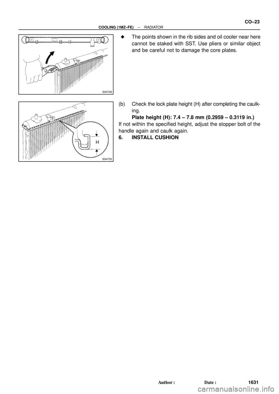
S04726
S04735
H
± COOLING (1MZ±FE)RADIATOR
CO±23
1631 Author�: Date�: �
The points shown in the rib sides and oil cooler near here
cannot be staked with SST. Use pliers or similar object
and be careful not to damage the core plates.
(b) Check the lock plate height (H) after completing the caulk-
ing.
Plate height (H): 7.4 ± 7.8 mm (0.2959 ± 0.3119 in.)
If not within the specified height, adjust the stopper bolt of the
handle again and caulk again.
6. INSTALL CUSHION
Page 2429 of 4770
P00495
Outside
Inside
± DIAGNOSTICSENGINE (5S±FE)
DI±9
244 Author�: Date�:
2 Is engine cranked?
NO Proceed to page ST±2 and continue to
troubleshoot.
YES
3 Does engine start?
NO Go to step 7.
YES
4 Check air filter.
PREPARATION:
Remove the air filter.
CHECK:
Visually check that the air filter is not dirty or excessive oily.
HINT:
If necessary, clean the filter with compressed air. First blow from
inside thoroughly, then blow from outside of the filter.
NG Repair or replace.
OK
Page 2435 of 4770

DI±15
250 Author�: Date�:
(b) TOYOTA Enhanced Signals.
TOYOTA hand±held tester displayMeasurement ItemNormal Condition*1
MISFIRE RPMEngine RPM for first misfire rangeMi")
± DIAGNOSTICSENGINE (5S±FE)
DI±15
250 Author�: Date�:
(b) TOYOTA Enhanced Signals.
TOYOTA hand±held tester displayMeasurement ItemNormal Condition*1
MISFIRE RPMEngine RPM for first misfire rangeMisfire 0: 0 rpm
MISFIRE LOADEngine load for first misfire rangeMisfire 0: 0 g/r
INJECTORFuel injection time for cylinder No.1Idling: 2.9 ~ 5.1 ms
IAC DUTY RATIOIntake Air Control Valve Duty Ratio
Opening ratio rotary solenoid type IAC valveIdling: 25 ~ 62 %
STARTER SIGStarter SignalCranking: ON
CTP SIGClosed Throttle Position SignalThrottle fully closed: ON
A/C SIGA/C Switch SignalA/C ON: ON
PNP SIGPark/Neutral Position Switch SignalP or N position: ON
ELECTCL LOAD SIGElectrical Load SignalDefogger S/W ON: ON
STOP LIGHT SWStop Light Switch SignalStop light switch ON: ON
PS OIL PRESS SWPower Steering Oil Pressure Switch SignalTurn steering wheel: ON
FC IDLFuel Cut Idle: Fuel cut when throttle valve fully
closed, during decelerationFuel cut operating: ON
FC TAUFuel Cut TAU: Fuel cut during very light loadFuel cut operating: ON
CYL#1, CYL#2, CYL#3, CYL#4Abnormal revolution variation for each cylinder0 %
IGNITIONTotal number of ignition for every 1,000 revolu-
tions0 ~ 2,000 rpm
EGR SYSTEMEGR system operating conditionIdling: OFF
FUEL PUMPFuel Pump SignalIdling: ON
A/C CUT SIGA/C Cut SignalA/C S/W OFF: ON
A/C MAG CLUTCHA/C Switch SignalA/C ON: ON
EVAP (PURGE) VSVEVAP VSV SignalVSV operating: Avove 30 %
VAPOR PRESS VSVVapor Pressure VSV SignalVSV operating: ON
TOTAL FT B1Total Fuel Trim Bank 1: Average value for fuel
trim system of bank 1Idling: 0.8 ~ 1.2 V
O2 LR B1, S1 *2
Heated Oxygen Sensor Lean Rich Bank 1 Sen-
sor 1: Response time for oxygen sensor output to
switch from lean to rich
Idling after warming up: 0 ~ 1,000 msec.
O2 RL B1, S1 *2
Heated Oxygen Sensor Rich Lean Bank 1 Sen-
sor 1: Response time for oxygen sensor output to
switch from rich to lean
Idling after warming up: 0 ~ 1,000 msec.
*1: If no conditions are specifically stated for ºldlingº, it means the shift lever is at N or P position, the A/C
switch is OFF and all accessory switches are OFF.
*2: Except California Specification vehicles.
Page 2439 of 4770

DI±19
254 Author�: Date�:
DTC No.
(See Page)Detection ItemTrouble AreaMIL*1Memory
P0500
(DI±145)Vehicle Speed Sensor
Malfunction
�Combination meter
�Open or short in N")
± DIAGNOSTICSENGINE (5S±FE)
DI±19
254 Author�: Date�:
DTC No.
(See Page)Detection ItemTrouble AreaMIL*1Memory
P0500
(DI±145)Vehicle Speed Sensor
Malfunction
�Combination meter
�Open or short in No.1 vehicle speed sensor circuit
�No.1 vehicle speed sensor
�ECM
��
P0505
(DI±148)Idle Control System
Malfunction
�IAC valve is stuck or closed
�Open or short in IAC valve circuit
�Open or short in A/C switch circuit
�Air intake (hose loose)
�ECM
��
*1: ����� MIL lights up
2. MANUFACTURER CONTROLLED
DTC No.
(See Page)Detection ItemTrouble AreaMIL*1Memory
*2
P1130
(DI±152)A/F Sensor Circuit
Range/Performance Malfunction�Open or short in A/F sensor circuit
�A/F sensor
�ECM
��
*2
P1133
(DI±157)A/F Sensor Circuit Response
Malfunction�A/F sensor��
*2
P1135
(DI±161)A/F Sensor Heater Circuit
Malfunction�Open or short in heater circuit of A/F sensor
�A/F sensor heater
�ECM
��
P1300
(DI±163)Igniter Circuit Malfunction (No.1)
�Open or short in IGF or IGT circuit from igniter to ECM
�Ignition coil (No.1)
�ECM
��
P1310
(DI±163)Igniter Circuit Malfunction (No.2)
�Open or short in IGF or IGT circuit from igniter to ECM
�Ignition coil (No.2)
�ECM
��
P1335
(DI±169)Crankshaft Position Sensor Cir-
cuit Malfunction
(During engine running)�Open short in crankshaft position sensor circuit
�Crankshaft position sensor
�ECM
±�
*3
P1520
(DI±170)Stop Light Switch Signal Mal-
function�Short in stop light switch signal circuit
�Stop light switch
�ECM
��
P1600
(DI±173)ECM BATT Malfunction�Open in back up power source circuit
�ECM��
*3
P1780
(DI±175)Park/Neutral Position Switch
Malfunction�Short in park/neutral position switch circuit
�Park/neutral position switch
�ECM
��
*1: ����� MIL lights up
*
2: Only for California Specification vehicles
*
3: Only for A/T models
Page 2441 of 4770
DI1JS±03
A03431
A03430
A03537
Crankshaft
Position
SensorVSV for EGRDLC1Camshaft Position
SensorInjectorECMThrottle Position SensorManifold Absolute
Pressure Sensor
Combination Meter
(Speedometer)
DLC3
Heated Oxygen
Sensor
(Bank 1 Sensor 2)
Intake Air Temp.
Sensor
VSV for EVAP
Idle Air Control
Valve
Ignition Coil (No.1, No.2) Park/Neutral Position
Switch Engine Coolant Temp.
Sensor Heated Oxygen Sensor
(Bank 1 Sensor 1) *1 A/F Sensor *2 Knock
Sensor 1
*1: Except California Specification vehicles
*2: Only for California Specification vehicles
Vapor Pressure Sensor
Charcoal Canister
VSV for
Vapor Pressure Sensor
± DIAGNOSTICSENGINE (5S±FE)
DI±21
256 Author�: Date�:
PARTS LOCATION
Page 2442 of 4770

257 Author�: Date�:
TERMINALS OF ECM
Without engine immobiliser system
Symbols (Terminals No.)Wiring ColorConditionSTD Voltag")
DI1JT±03
D00032
E9E8E7
ECM Terminals DI±22
± DIAGNOSTICSENGINE (5S±FE)
257 Author�: Date�:
TERMINALS OF ECM
Without engine immobiliser system
Symbols (Terminals No.)Wiring ColorConditionSTD Voltage (V)
BATT (E7 ± 1) ± E1 (E9 ± 14)B ± Y e BRAlways9 ~ 14
+ B (E7 ± 12) ± E1 (E9 ± 14)B ± Y e BRIG switch ON9 ~ 14
VC (E8 ± 1) ± E2 (E8 ± 9)Ye BRIG switch ON4.5 ~ 5.5
VTA (E8 11) E2 (E8 9)LGBR
IG switch ON
Throttle valve fully closed0.3 ~ 1.0
VTA (E8 ± 11) ± E2 (E8 ± 9)LG e BRIG switch ON
Throttle valve fully open3.2 ~ 4.9
PIM (E8 2) E2 (E8 9)BYBR
IG switch ON3.3 ~ 3.9
PIM (E8 ± 2) ± E2 (E8 ± 9)B ± Y e BRApply vacuum 26.7 kPa (200 mmHg, 7.9 in.Hg)2.5 ~ 3.1
THA (E8 ± 3) ± E2 (E8 ± 9)Y ± B e BRIdling, Intake air temp. 20°C (68° F)0.5 ~ 3.4
THW (E8 ± 4) ± E2 (E8 ± 9)G ± B e BRIdling, Engine coolant temp. 80°C (176°F) 0.2 ~ 1.0
STA (E7 11) E1 (E9 14)*1 GR e BRCranking6.0 or moreSTA (E7 ± 11) ± E1 (E9 ± 14) *2 B ± O e BRCranking6.0 or more
IG switch ON9 ~ 14
#10 (E9 ± 12) ± E01 (E9 ± 13) L e BRIdlingPulse generation
(See page DI±89)
IG switch ON9 ~ 14
#20 (E9 ± 11) ± E01 (E9 ± 13)R e BRIdlingPulse generation
(See page DI±89)
IG switch ON9 ~ 14
#30 (E9 ± 25) ± E01 (E9 ± 13)Y e BRIdlingPulse generation
(See page DI±89)
IG switch ON9 ~ 14
#40 (E9 ± 24) ± E01 (E9 ± 13)W e BRIdlingPulse generation
(See page DI±89)
IGT1 (E9 ± 20) ± E1 (E9 ± 14)B e BRIdlingPulse generation
(See page DI±163)
IGT2 (E9 ± 19) ± E1 (E9 ± 14)Y ± R e BRIdlingPulse generation
(See page DI±163)
IG switch ON, Disconnect ignition coil connector4.5 ~ 5.5
IGF (E9 ± 3) ± E1 (E9 ± 14)W ± R e BRIdlingPulse generation
(See page DI±163)
*1: TMC made
*2: TMMK made


DL")