Page 2356 of 4770
WATER PUMP
1582 Author�: Date�:
INSTALLATION
1. INSTALL WATER PUMP TO WATER PUMP COVER
Install a new gasket and the")
CO06B±03
N00918
S06015
Connect
Z19283
1
3
2
S05924
S05599
CO±8
± COOLING (5S±FE)WATER PUMP
1582 Author�: Date�:
INSTALLATION
1. INSTALL WATER PUMP TO WATER PUMP COVER
Install a new gasket and the water pump with the 3 bolts.
Torque: 8.8 N´m (90 kgf´cm, 78 in.´lbf)
2. INSTALL WATER PUMP AND WATER PUMP COVER
ASSEMBLY
(a) Install new O±ring and gasket to water pump cover.
(b) Install a new O±ring to the water bypass pipe.
(c) Apply soapy water to the O±ring on the water bypass
pipe.
(d) Connect the water pump cover to the water bypass pipe.
Do not install the nuts yet.
(e) Install the water pump with the 3 bolts. Tighten the bolts
in the sequence shown.
Torque: 8.8 N´m (90 kgf´cm, 78 in.´lbf)
(f) Install the 2 nuts holding the water pump cover to the wa-
ter bypass pipe.
Torque: 9.3 N´m (95 kgf´cm, 82 in.´lbf)
3. INSTALL GENERATOR DRIVE BELT ADJUSTING BAR
(a) Install the adjusting bar with the bolt.
Torque: 22 N´m (224 kgf´cm, 16 ft´lbf)
(b) Install the engine wire clamp to the adjusting bar.
(c) Install the crankshaft position sensor connector to the
bracket on the adjusting bar.
4. w/ Oil Cooler:
INSTALL A/C COMPRESSOR (See page EM±75)
5. INSTALL NO.2 IDLER PULLEY (See page EM±23)
Page 2358 of 4770
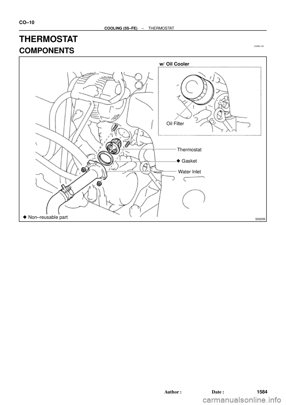
CO06C±03
S05299
w/ Oil Cooler
Oil Filter
Thermostat
� Gasket
Water Inlet
� Non±reusable part CO±10
± COOLING (5S±FE)THERMOSTAT
1584 Author�: Date�:
THERMOSTAT
COMPONENTS
Page 2359 of 4770
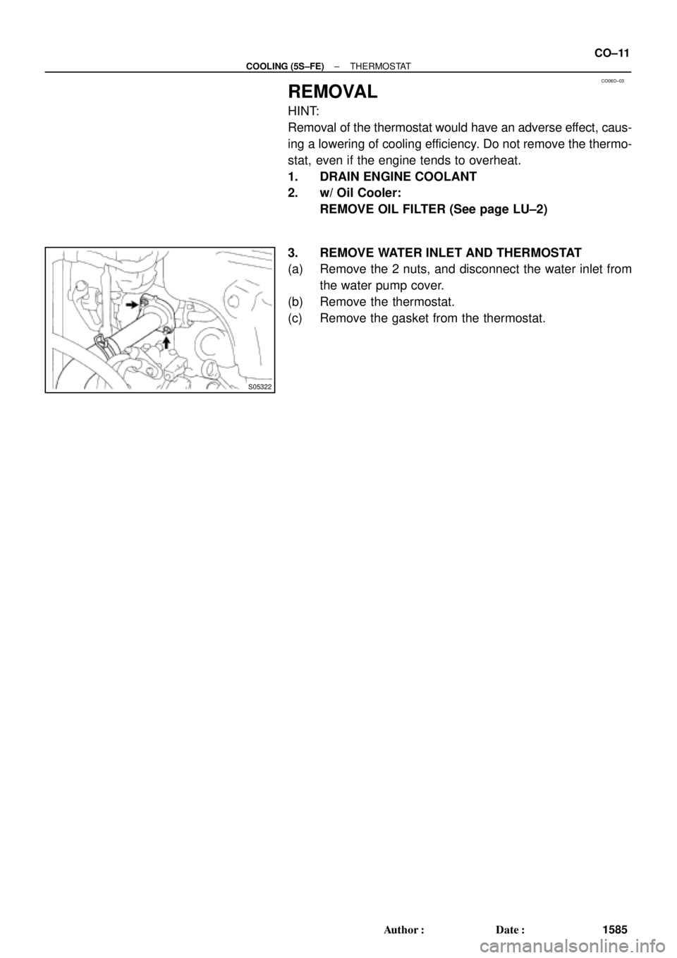
CO06D±03
S05322
± COOLING (5S±FE)THERMOSTAT
CO±11
1585 Author�: Date�:
REMOVAL
HINT:
Removal of the thermostat would have an adverse effect, caus-
ing a lowering of cooling efficiency. Do not remove the thermo-
stat, even if the engine tends to overheat.
1. DRAIN ENGINE COOLANT
2. w/ Oil Cooler:
REMOVE OIL FILTER (See page LU±2)
3. REMOVE WATER INLET AND THERMOSTAT
(a) Remove the 2 nuts, and disconnect the water inlet from
the water pump cover.
(b) Remove the thermostat.
(c) Remove the gasket from the thermostat.
Page 2361 of 4770
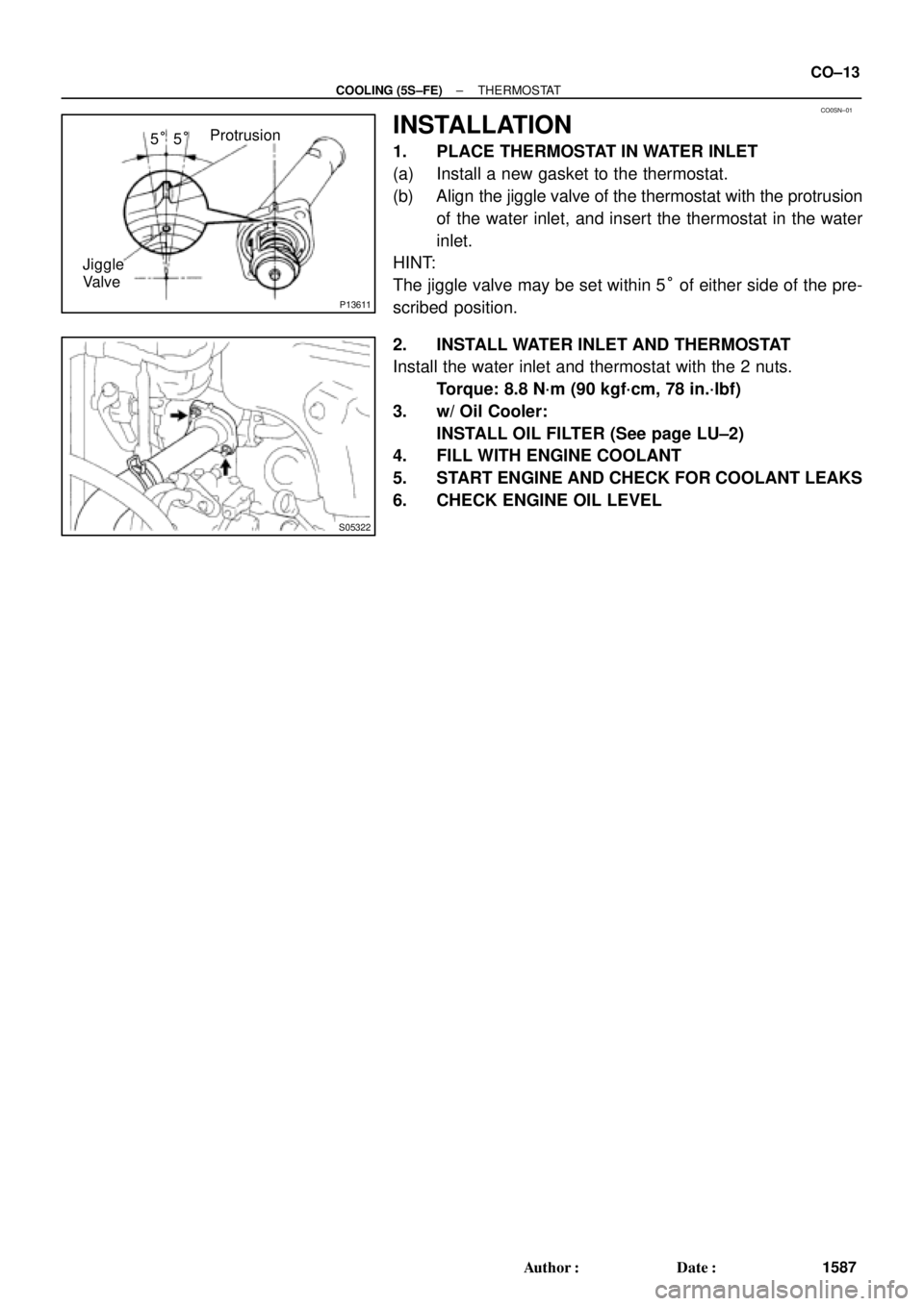
CO0SN±01
P13611
Protrusion
Jiggle
Valve5°5°
S05322
± COOLING (5S±FE)THERMOSTAT
CO±13
1587 Author�: Date�:
INSTALLATION
1. PLACE THERMOSTAT IN WATER INLET
(a) Install a new gasket to the thermostat.
(b) Align the jiggle valve of the thermostat with the protrusion
of the water inlet, and insert the thermostat in the water
inlet.
HINT:
The jiggle valve may be set within 5° of either side of the pre-
scribed position.
2. INSTALL WATER INLET AND THERMOSTAT
Install the water inlet and thermostat with the 2 nuts.
Torque: 8.8 N´m (90 kgf´cm, 78 in.´lbf)
3. w/ Oil Cooler:
INSTALL OIL FILTER (See page LU±2)
4. FILL WITH ENGINE COOLANT
5. START ENGINE AND CHECK FOR COOLANT LEAKS
6. CHECK ENGINE OIL LEVEL
Page 2364 of 4770
CO06I±03
S05951
No.2 Electric
Cooling Fan
Connector
Radiator Assembly
Lower Radiator
Support
Lower Radiator Hose
Upper Radiator Hose
Oil Cooler Hose for A/TUpper Radiator Support
No.1 Electric Cooling Fan Connector
ECT Switch Connector
for Electric Cooling Fan Upper Radiator Support Radiator Reservoir Hose CO±16
± COOLING (5S±FE)RADIATOR
1590 Author�: Date�:
COMPONENTS
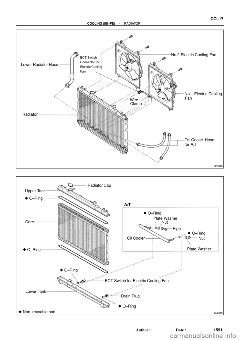
Page 2365 of 4770
S05948
Lower Radiator Hose
RadiatorNo.2 Electric Cooling Fan
No.1 Electric Cooling
Oil Cooler Hose
for A/T
ECT Switch
Connector for
Electric Cooling
Fan
FanWireClamp
S05240
Upper Tank
� O±Ring
Core
Lower Tank
ECT Switch for Electric Cooling Fan
Drain PlugOil Cooler A/T
Pipe
Plate WasherNut
� O±Ring� O±Ring
� O±Ring Radiator Cap
Nut Plate Washer
� Non±reusable part� O±Ring
� O±Ring
± COOLING (5S±FE)RADIATOR
CO±17
1591 Author�: Date�:
Page 2366 of 4770
RADIATOR
1592 Author�: Date�:
REMOVAL
1. DRAIN ENGINE COOLANT
2. REMOVE RADIATOR ASSEMBLY
(a) Disconnect the No.1 electric cooling fan connector.
(b) Disconn")
CO06J±04
S05955
CO±18
± COOLING (5S±FE)RADIATOR
1592 Author�: Date�:
REMOVAL
1. DRAIN ENGINE COOLANT
2. REMOVE RADIATOR ASSEMBLY
(a) Disconnect the No.1 electric cooling fan connector.
(b) Disconnect the No.2 electric cooling fan connector.
(c) Disconnect the ECT switch connector for the electric cool-
ing fan.
(d) Disconnect the upper radiator hose from the radiator.
(e) Disconnect the lower radiator hose from the water inlet.
(f) Disconnect the radiator reservoir hose from the radiator.
(g) A/T:
Disconnect the 2 oil cooler hoses from the oil cooler pipes.
(h) Remove the 2 bolts and 2 upper radiator supports.
(i) Remove the radiator assembly.
(j) Remove the 2 lower radiator supports.
(k) Remove the lower radiator hose from the radiator.
(l) A/T:
Remove the 2 oil cooler hoses from the radiator.
3. REMOVE NO.1 ELECTRIC COOLING FAN FROM RA-
DIATOR
(a) Disconnect the ECT switch connector for the cooling fan.
(b) Disconnect the ECT switch wire clamp for the cooling fan
from the bracket of the radiator.
(c) Remove the 2 bolts and cooling fan.
4. REMOVE NO.2 ELECTRIC COOLING FAN FROM RA-
DIATOR
Remove the 2 bolts and cooling fan.
Page 2367 of 4770
RADIATOR
CO±19
1593 Author�: Date�:
DISASSE")
CO06K±03
CO1205
Dimension ºBº
Overhaul HandleStopper Bolt SSTPart ºAº
Claw
S04699
Stopper
BoltSSTTank
Lock
Plate
S04703
Ta p
S04705
± COOLING (5S±FE)RADIATOR
CO±19
1593 Author�: Date�:
DISASSEMBLY
1. REMOVE ECT SWITCH
(a) Remove the ECT switch.
(b) Remove the O±ring.
2. REMOVE DRAIN PLUG
(a) Remove the drain plug.
(b) Remove the O±ring.
3. ASSEMBLE SST
SST 09230±01010
(a) Install the claw to the overhaul handle, inserting it in the
hole in part ºAº as shown in the diagram.
(b) While gripping the handle, adjust the stopper bolt so that
dimension ºBº is as shown in the illustration.
Dimension: 0.2 ± 0.3 mm (0.008 ± 0.012 in)
NOTICE:
If this adjustment is not done the claw may be damaged.
4. UNCAULK LOCK PLATES
Using SST to release the caulking, squeeze the handle until
stopped by the stopper bolt.
SST 09230±01010
5. REMOVE TANKS AND O±RINGS
Lightly tap the bracket of the radiator (or radiator inlet or outlet)
with a soft±faced hammer, and remove the tank and the O±ring.
6. A/T:
REMOVE OIL COOLER FROM LOWER TANK
(a) Loosen the nut, and remove the cooler pipe.
(b) Remove the 2 nuts and plate washers.
(c) Remove the oil cooler and 2 O±rings.