Page 2144 of 4770
Z15788
Engine coolant temperature gauge
Ignition
Switch
BatteryWire Harness SideTest Bulb
(3.4 W)
N20216
C
B
A
N21646
Z14205
Warning Light
Ignition
Switch
Battery
1 BE±50
± BODY ELECTRICALCOMBINATION METER
2270 Author�: Date�:
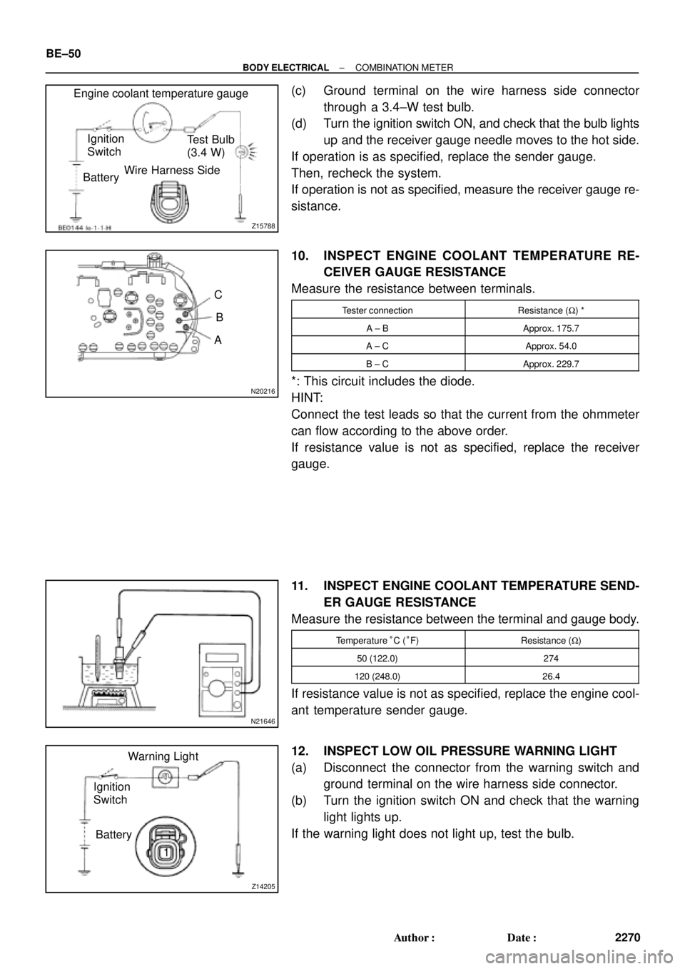
(c) Ground terminal on the wire harness side connector
through a 3.4±W test bulb.
(d) Turn the ignition switch ON, and check that the bulb lights
up and the receiver gauge needle moves to the hot side.
If operation is as specified, replace the sender gauge.
Then, recheck the system.
If operation is not as specified, measure the receiver gauge re-
sistance.
10. INSPECT ENGINE COOLANT TEMPERATURE RE-
CEIVER GAUGE RESISTANCE
Measure the resistance between terminals.
Tester connectionResistance (W) *
A ± BApprox. 175.7
A ± CApprox. 54.0
B ± CApprox. 229.7
*: This circuit includes the diode.
HINT:
Connect the test leads so that the current from the ohmmeter
can flow according to the above order.
If resistance value is not as specified, replace the receiver
gauge.
11. INSPECT ENGINE COOLANT TEMPERATURE SEND-
ER GAUGE RESISTANCE
Measure the resistance between the terminal and gauge body.
Temperature °C (°F)Resistance (W)
50 (122.0)274
120 (248.0)26.4
If resistance value is not as specified, replace the engine cool-
ant temperature sender gauge.
12. INSPECT LOW OIL PRESSURE WARNING LIGHT
(a) Disconnect the connector from the warning switch and
ground terminal on the wire harness side connector.
(b) Turn the ignition switch ON and check that the warning
light lights up.
If the warning light does not light up, test the bulb.
Page 2145 of 4770
N06640
BE1217
Warning Light
Ignition
Switch
Battery
N02346
OFF
ON
1 2
N01212
BE1217
Warning Light
Ignition
Switch
Battery
± BODY ELECTRICALCOMBINATION METER
BE±51
2271 Author�: Date�:
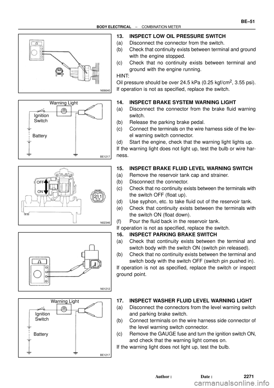
13. INSPECT LOW OIL PRESSURE SWITCH
(a) Disconnect the connector from the switch.
(b) Check that continuity exists between terminal and ground
with the engine stopped.
(c) Check that no continuity exists between terminal and
ground with the engine running.
HINT:
Oil pressure should be over 24.5 kPa (0.25 kgf/cm
2, 3.55 psi).
If operation is not as specified, replace the switch.
14. INSPECT BRAKE SYSTEM WARNING LIGHT
(a) Disconnect the connector from the brake fluid warning
switch.
(b) Release the parking brake pedal.
(c) Connect the terminals on the wire harness side of the lev-
el warning switch connector.
(d) Start the engine, check that the warning light lights up.
If the warning light does not light up, test the bulb or wire har-
ness.
15. INSPECT BRAKE FLUID LEVEL WARNING SWITCH
(a) Remove the reservoir tank cap and strainer.
(b) Disconnect the connector.
(c) Check that no continuity exists between the terminals with
the switch OFF (float up).
(d) Use syphon, etc. to take fluid out of the reservoir tank.
(e) Check that continuity exists between the terminals with
the switch ON (float down).
(f) Pour the fluid back in the reservoir tank.
If operation is not as specified, replace the switch.
16. INSPECT PARKING BRAKE SWITCH
(a) Check that continuity exists between the terminal and
switch body with the switch ON (switch pin released).
(b) Check that no continuity exists between the terminal and
switch body with the switch OFF (switch pin pushed in).
If operation is not as specified, replace the switch or inspect
ground point.
17. INSPECT WASHER FLUID LEVEL WARNING LIGHT
(a) Disconnect the connectors from the level warning switch
and parking brake switch.
(b) Connect terminals on the wire harness side connector of
the level warning switch connector.
(c) Remove the GAUGE fuse and turn the ignition switch ON,
and check that the warning light comes on.
If the warning light does not light up, test the bulb.
Page 2151 of 4770
N21371
6
4
BE4029
Tester Probe
Tin FoilHeat Wire
BE0123
At Center
BE0124
0 VoltSeveral
Volts
Broken
Wire
± BODY ELECTRICALDEFOGGER SYSTEM
BE±57
2277 Author�: Date�:
5. w/ Heater:
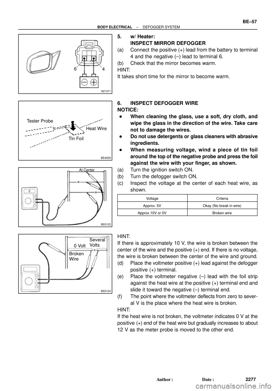
INSPECT MIRROR DEFOGGER
(a) Connect the positive (+) lead from the battery to terminal
4 and the negative (±) lead to terminal 6.
(b) Check that the mirror becomes warm.
HINT:
It takes short time for the mirror to become warm.
6. INSPECT DEFOGGER WIRE
NOTICE:
�When cleaning the glass, use a soft, dry cloth, and
wipe the glass in the direction of the wire. Take care
not to damage the wires.
�Do not use detergents or glass cleaners with abrasive
ingredients.
�When measuring voltage, wind a piece of tin foil
around the top of the negative probe and press the foil
against the wire with your finger, as shown.
(a) Turn the ignition switch ON.
(b) Turn the defogger switch ON.
(c) Inspect the voltage at the center of each heat wire, as
shown.
VoltageCriteria
Approx. 5VOkay (No break in wire)
Approx.10V or 0VBroken wire
HINT:
If there is approximately 10 V, the wire is broken between the
center of the wire and the positive (+) end. If there is no voltage,
the wire is broken between the center of the wire and ground.
(d) Place the voltmeter positive (+) lead against the defogger
positive (+) terminal.
(e) Place the voltmeter negative (±) lead with the foil strip
against the heat wire at the positive (+) terminal end and
slide it toward the negative (±) terminal end.
(f) The point where the voltmeter deflects from zero to sever-
al V is the place where the heat wire is broken.
HINT:
If the heat wire is not broken, the voltmeter indicates 0 V at the
positive (+) end of the heat wire but gradually increases to about
12 V as the meter probe is moved to the other end.
Page 2182 of 4770
N21545
NoiseGlass Printed Antenna
Signal
Radio
Noise
Noise
Noise
Noise
N21546
to Radio
Battery
Choke Coil
Noise
BE±88
± BODY ELECTRICALAUDIO SYSTEM
2308 Author�: Date�:
(b) Matlers that require attention when checking:
�Noise coming into the radio usually has no harm for
practical use as the noise protection is taken and it
is hardly thinkable for an extremely loud noise to
come in. When extremely loud noise comes into the
radio, check if the grounding is normal where the
antenna is installed.
�Check if all the regular noise prevention parts are
properly installed and if there is any installation of
non±authorized parts and non±authorized wiring.
�If you leave the radio out of tune (not tuning), it is
easy to diagnose the phenomenon as noise occurs
frequently.
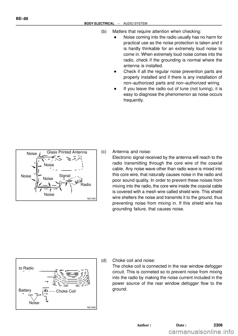
(c) Antenna and noise:
Electronic signal received by the antenna will reach to the
radio transmitting through the core wire of the coaxial
cable. Any noise wave other than radio wave is mixed into
this core wire, that naturally causes noise in the radio and
poor sound quality. In order to prevent these noises from
mixing into the radio, the core wire inside the coaxial cable
is covered with a mesh wire called shield wire. This shield
wire shelters the noise and transmits it to the ground, thus
preventing noise from mixing in. If this shield wire has
grounding failure, that causes noise.
(d) Choke coil and noise:
The choke coil is connected in the rear window defogger
circuit. This is conneted so to prevent noise from mixing
into the radio by making the noise current included in the
power source of the rear window defogger flow to the
ground.
Page 2183 of 4770
I00399
Plug (Main)Antenna
Terminal
(Main)
Plug (Sub)Antenna
Terminal
(Sub) (1)
(3)(2)
(4)
I00402
I00403N21548
I00407
Ground point:
Antenna Cord
Center Brace
Pillar (RH)
Pillar (LH) Choke Coil
± BODY ELECTRICALAUDIO SYSTEM
BE±89
2309 Author�: Date�:
5. Glass printed antenna:
GROUNDING FOR THE ANTENNA CORD AND CHOKE
COIL
HINT:
During troubleshooting, in case that the antenna code continu-
ity check, grounding check and grounding check of the choke
coil are needed, please check refering to the following illustra-
tion.
Terminal connectionNormal condition
(1) e (2)Continuity
(3) e (4)Continuity
Page 2184 of 4770
I00400
PlugAntenna
Terminal
(1) (2)
I00427
I00428
I00429I00408
Ground point:
Antenna Cord
Center Brace Luggage Room (RH side)
Pillar (LH) Noise Filter BE±90
± BODY ELECTRICALAUDIO SYSTEM
2310 Author�: Date�:
6. Fixed mast antenna:
GROUNDING FOR THE ANTENNA CORD AND CHOKE
COIL
HINT:
During troubleshooting, in case that the antenna code continu-
ity check, grounding check and grounding check of the choke
coil are needed, please check refering to the following illustra-
tions.
Terminal connectionNormal condition
(1) e (2)Continuity
Page 2192 of 4770
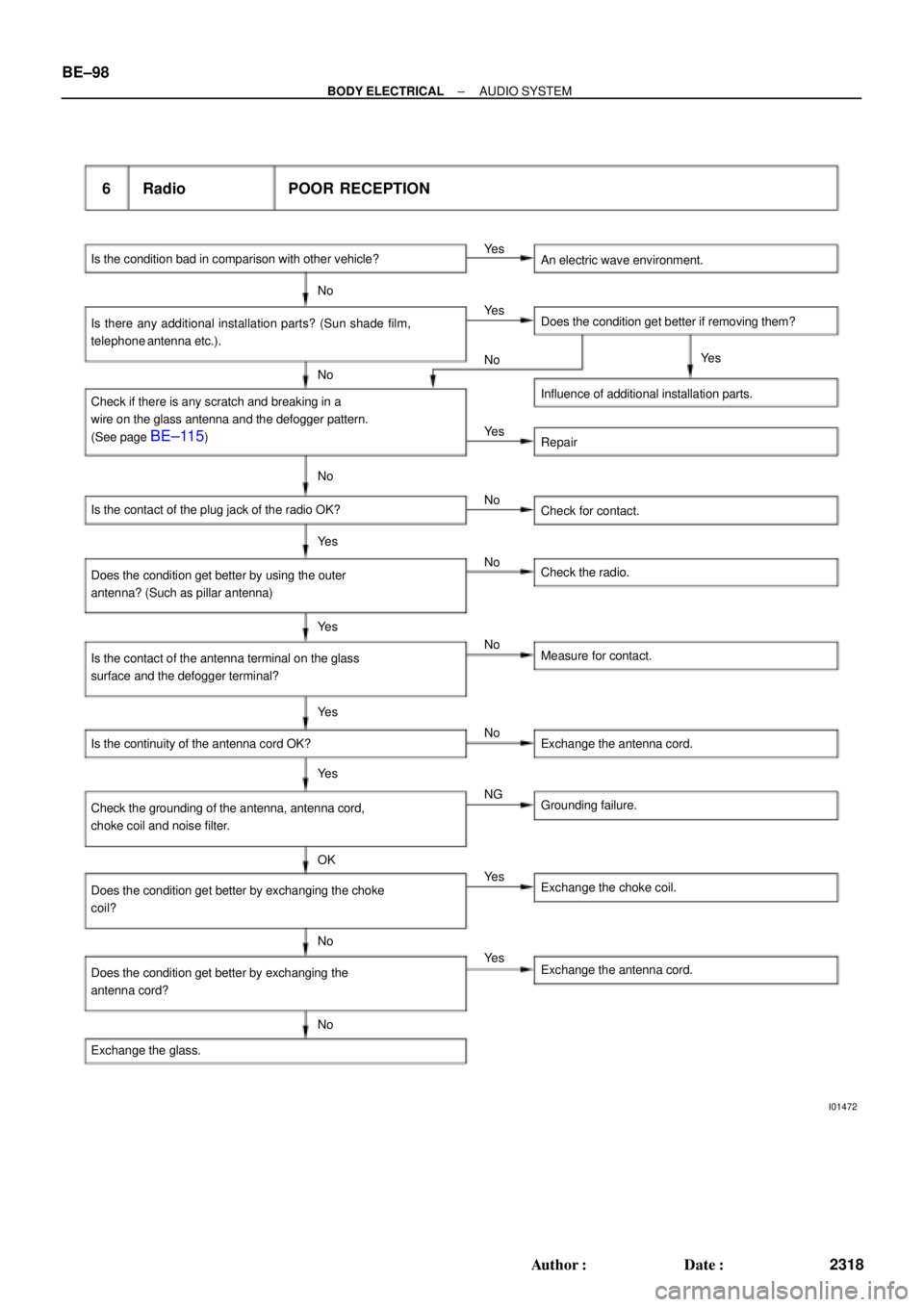
I01472
Is the condition bad in comparison with other vehicle?
6 Radio POOR RECEPTION
An electric wave environment.
Is there any additional installation parts? (Sun shade film,
telephone antenna etc.).Does the condition get better if removing them? Ye s
No
Ye s
No
Check if there is any scratch and breaking in a
wire on the glass antenna and the defogger pattern.
(See page
BE±115)Influence of additional installation parts. No
Repair Ye s
No
No
Is the contact of the plug jack of the radio OK?
Check for contact.
Ye s
No
Does the condition get better by using the outer
antenna? (Such as pillar antenna)Check the radio.
Ye s
No
Ye s
No Is the contact of the antenna terminal on the glass
surface and the defogger terminal?Measure for contact.
Is the continuity of the antenna cord OK? Exchange the antenna cord.
Check the grounding of the antenna, antenna cord,
choke coil and noise filter.Ye s
NG
Grounding failure.
OK
Does the condition get better by exchanging the choke
coil?Exchange the choke coil. Ye s
No
Ye s
Does the condition get better by exchanging the
antenna cord?Exchange the antenna cord.
Exchange the glass.NoYe s
BE±98
± BODY ELECTRICALAUDIO SYSTEM
2318 Author�: Date�:
Page 2205 of 4770
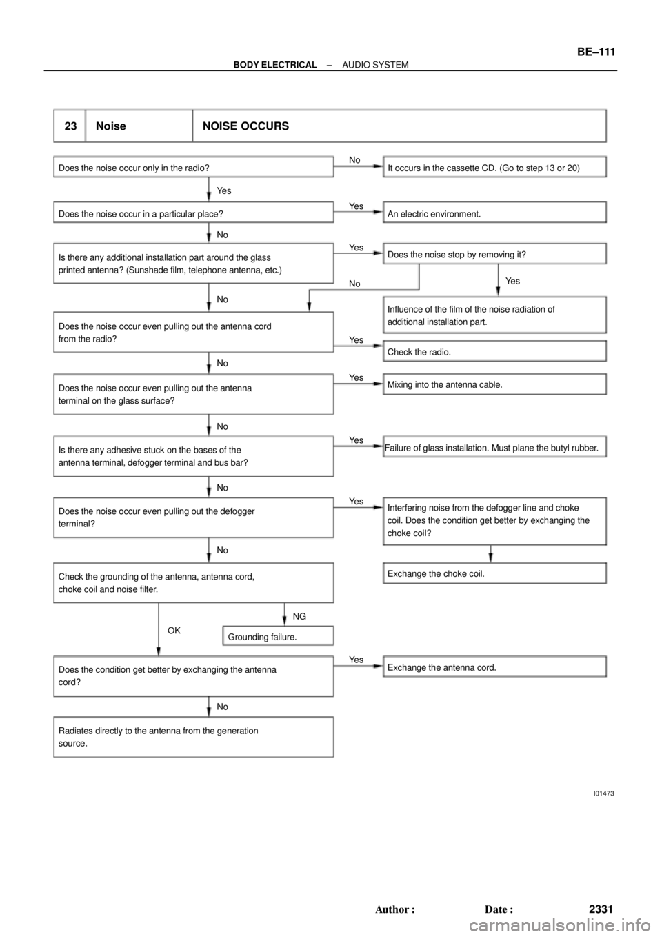
I01473
23 Noise NOISE OCCURS
Does the noise occur only in the radio? It occurs in the cassette CD. (Go to step 13 or 20)
Does the noise occur in a particular place? An electric environment.No
Ye s
Ye s
Is there any additional installation part around the glass
printed antenna? (Sunshade film, telephone antenna, etc.)Does the noise stop by removing it?
Influence of the film of the noise radiation of
additional installation part.
Does the noise occur even pulling out the antenna cord
from the radio?
Check the radio. No
No
NoNo Ye s
Ye s
Ye s
Does the noise occur even pulling out the antenna
terminal on the glass surface?Mixing into the antenna cable.
Is there any adhesive stuck on the bases of the
antenna terminal, defogger terminal and bus bar?Failure of glass installation. Must plane the butyl rubber.
Does the noise occur even pulling out the defogger
terminal?Interfering noise from the defogger line and choke
coil. Does the condition get better by exchanging the
choke coil? Ye s
Ye s
Ye s No
No
No
Check the grounding of the antenna, antenna cord,
choke coil and noise filter.Exchange the choke coil.
NG
Grounding failure.
Does the condition get better by exchanging the antenna
cord?
Radiates directly to the antenna from the generation
source.Exchange the antenna cord.
NoYe s OK
± BODY ELECTRICALAUDIO SYSTEM
BE±111
2331 Author�: Date�: