Page 1923 of 4770
AUTOMATIC TRANSAXLESERVICE SPECIFICATIONS ±
AX±127
SERVICE SPECIFICATIONS
SERVICE DATE
Second Coast Brake
Piston stroke2.0 ± 3.5 mm
0.079 ± 0.138 in.
Piston rod length95.2 mm
3.748 in.
96.3 mm
3.791 in.
Oil Pump
Body clearance STD0.07 ± 0.15 mm
0.0028 ± 0.0059 in.
Maximum0.30 mm
0.0118 in.
Tip clearance STD0.11 ± 0.14 mm
0.0043 ± 0.0055 in.
Maximum0.30 mm
0.0118 in.
Side clearance STD0.02 ± 0.05 mm
0.0008 ± 0.0020 in.
Maximum0.10 mm
0.0039 in.
Pump body bushing inside diameterMaximum38.18 mm
1.5031 in.
Stator shaft bushing inside diameter
Front side Maximum21.57 mm
0.8492 in.
Rear side Maximum27.07 mm
1.0657 in.
Direct Clutch
Piston stroke0.91 ± 1.35 mm
0.0358 ± 0.0531 in.
Drum bushing inside diameter48.27 mm
1.9004 in.
Flange thickness
2.70 mm
0.1063 in.
3.00 mm
0.1181 in.
Forward Clutch
Piston stroke1.79 ± 2.21 mm
0.0704 ± 0.0870 in.
Flange thickness
2.30 mm
0.0906 in.
2.70 mm
0.1063 in.
AX0H1±06
Page 1925 of 4770
Total No. of coils / Color
Upper valve body
Low coast modulator valve20.2 (0.79")
AUTOMATIC TRANSAXLESERVICE SPECIFICATIONS ±
AX±129
Valve Body Spring
SpringFree length / Coil outer diameter
mm (in.)Total No. of coils / Color
Upper valve body
Low coast modulator valve20.2 (0.795) / 7.9 (0.311)11.9 / Purple
B1 orifice control valve24.8 (0.976) / 6.4 (0.252)12.0 / White
Down±shift plug15.0 (0.591) / 11.0 (0.433)7.0 / None
Throttle valve31.5 (1.240) / 7.0 (0.276)11.4 / Green
Lock±up relay valve26.8 (1.055) / 10.2 (0.402)10.8 / Yellow
Lower valve body
2±3 shift valve28.0 (1.102) / 9.4 (0.370)10.3 / None
Second coast modulator valve20.2 (0.795) / 7.9 (0.311)11.9 / Purple
Accumulator control vavle25.1 (0.988) / 8.6 (0.339)8.0 / Red
Secondary regulator valve46.9 (1.846) / 5.9 (0.232)21.8 / None
Second lock valve20.7 (0.815) / 7.4 (0.291)9.5 / None
Reverse control valve38.1 (1.500) / 6.5 (0.256)19.0 / White/Purple
1±2 shift valve29.2 (1.150) / 8.9 (0.350)12.0 / Light Green
3±4 shift valve28.0 (1.102) / 7.6 (0.299)10.3 / None
Primary regulator valve36.6 (1.441) / 16.1 (0.634)6.3 / None
Cut±back valve21.8 (0.858) / 6.0 (0.236)13.5 / None
Solenoid modulator valve30.2 (1.189) / 5.6 (0.220)15.3 / Purple/Pink
Valve Body Key
KeyHeight
mm (in.)Width
mm (in.)Thickness
mm (in.)
Upper valve body
B1 orifice control valve8.9 (0.350)5.0 (0.197)3.2 (0.126)
Low coast modulator valve8.5 (0.335)5.0 (0.197)3.2 (0.126)
Lower valve body
Accumulator control valve8.5 (0.335)5.0 (0.197)3.2 (0.126)
Secondary regulator valve11.0 (0.433)5.0 (0.197)3.2 (0.126)
1±2 shift valve8.5 (0.335)5.0 (0.197)3.2 (0.126)
2±3 shift valve8.5 (0.335)5.0 (0.197)3.2 (0.126)
3±4 shift valve6.5 (0.256)5.0 (0.197)3.2 (0.126)
Second lock valve9.2 (0.362)5.0 (0.197)3.2 (0.126)
Second coast modulator valve8.0 (0.315)5.0 (0.197)3.2 (0.126)
Reverse control valve8.5 (0.335)5.0 (0.197)3.2 (0.126)
Cut±back valve9.2 (0.362)5.0 (0.197)3.2 (0.126)
Solenoid modulator valve8.5 (0.335)5.0 (0.197)3.2 (0.126)
Lock±up control valve9.2 (0.315)5.0 (0.197)3.2 (0.126)
Page 1928 of 4770
AUTOMATIC TRANSAXLESERVICE SPECIFICATIONS ±
AX±132
TORQUE SPECIFICATIONS
Part tightenedN´mkgf´cmft´lbf
Oil cooler pipe union2727520
Oil pan4.95043 in.´lbf
Valve body x Transaxle case1111 08
Accumulator x Cover101007
Oil pump x Transaxle case2222516
O/D case x Transaxle case2525018
Differential LH side bearing retainer1919514
Differential RH retainer1919514
Differential carrier cover3940029
Oil pump body x Stator shaft101007
Ring gear x Differential case1241,26091
Upper valve body x Lower valve body6.66758 in.´lbf
Accumulator cylinder x Valve body6.66758 in.´lbf
Solenoid x Valve body6.66758 in.´lbf
Counter drive gear lock nut2802,855206
Carrire cover x Transaxle case3940029
Parking lock pawl bracket7.47565 in.´lbf
Oil strainer x Transaxle case1111 08
AX04N±03
Page 1935 of 4770
VALVE BODY ASSEMBLY
AX±7
1927 Author�: Date�:
VALVE BODY ASSEMBLY
ON±VEHICLE REPAIR
1. DRAIN ATF
Using a hexagon wrench,")
AX03Q±02
AT3785
AT0103
D01019
Q05728
Connector
± AUTOMATIC TRANSAXLE (A541E)VALVE BODY ASSEMBLY
AX±7
1927 Author�: Date�:
VALVE BODY ASSEMBLY
ON±VEHICLE REPAIR
1. DRAIN ATF
Using a hexagon wrench, remove the drain plug and fluid into
the suitable container.
2. REMOVE OIL PAN AND GASKET
NOTICE:
Some fluid will remain in the oil pan.
Remove oil pan bolts, and carefully remove the pan assembly.
Discard the gasket.
3. EXAMINE PARTICLES IN PAN
Remove the magnets and use them to collect any steel chips.
Look at the chips and particles in the pan and magnet carefully
to anticipate what type of wear you will find in the transaxle.
�Steel (magnetic): bearing, gear and plate wear
�Brass (non±magnetic): bushing wear
4. REMOVE OIL STRAINER AND APPLY PIPE BRACKET
(a) Remove the 3 bolts and oil strainer.
NOTICE:
Be careful as oil will come out of the strainer when it is re-
moved.
(b) Remove the 3 bolts and apply pipe bracket.
5. REMOVE OIL PIPES
Pry up both pipe ends with a large screwdriver and remove the
5 pipes.
6. DISCONNECT SOLENOID CONNECTORS
Page 1936 of 4770
D01020
D01021
D01059
D01058
D01023
AX±8
± AUTOMATIC TRANSAXLE (A541E)VALVE BODY ASSEMBLY
1928 Author�: Date�:
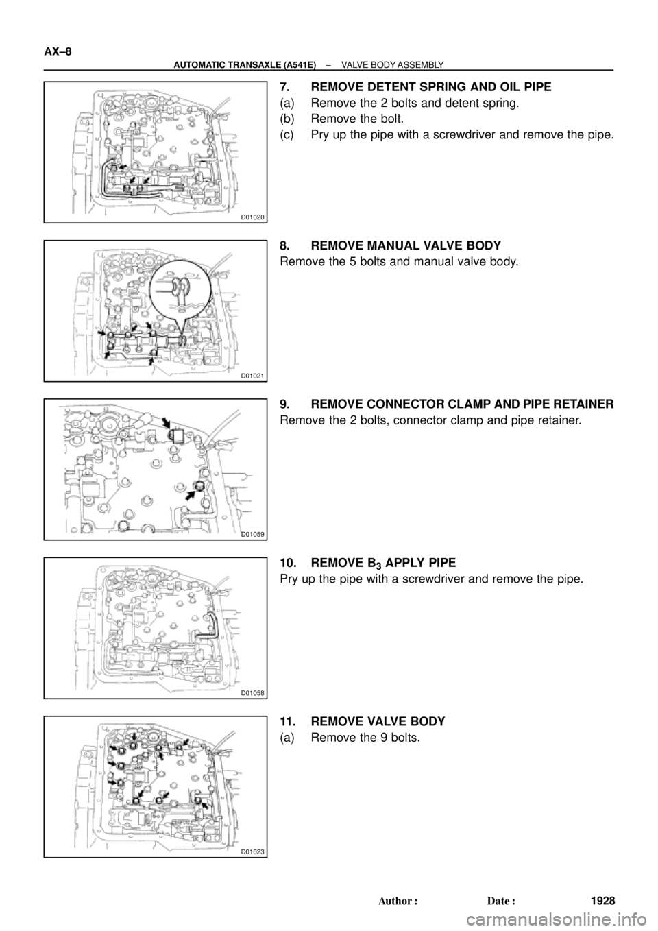
7. REMOVE DETENT SPRING AND OIL PIPE
(a) Remove the 2 bolts and detent spring.
(b) Remove the bolt.
(c) Pry up the pipe with a screwdriver and remove the pipe.
8. REMOVE MANUAL VALVE BODY
Remove the 5 bolts and manual valve body.
9. REMOVE CONNECTOR CLAMP AND PIPE RETAINER
Remove the 2 bolts, connector clamp and pipe retainer.
10. REMOVE B
3 APPLY PIPE
Pry up the pipe with a screwdriver and remove the pipe.
11. REMOVE VALVE BODY
(a) Remove the 9 bolts.
Page 1939 of 4770

BAmm (in.)
Q05728
Connector
± AUTOMATIC TRANSAXLE (A541E)VALVE BODY ASSEMBLY
AX±11
1931 Author�: Date�:
18. INSTALL CONNECTOR CLAMP AND PIPE RETAINER
(a) Ins")
D01059
A
B
D01021
B
B
A
Z19257
30
(1.18)
BAmm (in.)
Q05728
Connector
± AUTOMATIC TRANSAXLE (A541E)VALVE BODY ASSEMBLY
AX±11
1931 Author�: Date�:
18. INSTALL CONNECTOR CLAMP AND PIPE RETAINER
(a) Install the connector clamp and pipe retainer.
(b) Install and torque the 2 bolts.
Bolt length:
Bolt A: 48 mm (1.890 in.)
Bolt B: 39 mm (1.535 in.)
Torque: 11 N´m (110 kgf´cm, 8 ft´lbf)
19. INSTALL MANUAL VALVE BODY
(a) Align the manual valve with the pin on the manual shaft
lever.
(b) Lower the manual valve body into place.
(c) Hand tighten the 5 bolts first. Then, tighten them with a
torque wrench.
Bolt length:
Bolt A: 22 mm (0.866 in.)
Bolt B: 37 mm (1.457 in.)
Torque: 11 N´m (110 kgf´cm, 8 ft´lbf)
20. INSTALL DETENT SPRING AND OIL PIPE
(a) Place the detent springs on the manual valve body and
hand tighten the 2 bolts first. Then, tighten them with a
torque wrench.
Bolt length:
Bolt A: 14 mm (0.551 in.)
Bolt B: 37 mm (1.457 in.)
Torque: 11 N´m (110 kgf´cm, 8 ft´lbf)
(b) Check that the manual valve lever is touching the center
of the detent spring tip roller.
(c) Using a plastic hammer, install the pipe into the position.
NOTICE:
Be careful not to bend or damage the pipe.
(d) Install and torque the bolt.
Torque: 10 N´m (100 kgf´cm, 7 ft´lbf)
21. CONNECT SOLENOID CONNECTORS
22. INSTALL OIL PIPES
Using a plastic hammer, install the pipes into the positions.
NOTICE:
Be careful not to bend or damage the pipes.
Page 1940 of 4770
Z19256
BA
B A
AT3741
AT3785
AX±12
± AUTOMATIC TRANSAXLE (A541E)VALVE BODY ASSEMBLY
1932 Author�: Date�:
23. INSTALL OIL STRAINER AND APPLY PIPE BRACKET
(a) Install the oil strainer and apply pipe bracket.
(b) Install and torque the 6 bolts.
Bolt length:
Bolt A: 22 mm (0.866 in.)
Bolt B: 53 mm (2.087 in.)
Torque:
Bolt A: 10 N´m (100 kgf´cm, 7 ft´lbf)
Bolt B: 11 N´m (110 kgf´cm, 8 ft´lbf)
24. INSTALL MAGNETS IN PLACE
Install the 3 magnets in the indentations of the oil pan, as shown
in the illustration.
NOTICE:
Make sure that the magnet does not interfere with the oil
pipes.
25. INSTALL OIL PAN AND GASKET
(a) Install the oil pan and a new gasket.
(b) Install and torque the 17 new bolts.
Torque: 7.8 N´m (80 kgf´cm, 69 in.´lbf)
26. INSTALL AND TORQUE DRAIN PLUG
Torque: 49 N´m (500 kgf´cm, 36 ft´lbf)
27. FILL ATF AND CHECK FLUID LEVEL
(See page DI±438)
Page 1943 of 4770
Q00394
SST
AX03S±01
Q06348
SST
Q00238
SST
± AUTOMATIC TRANSAXLE (A541E)DIFFERENTIAL OIL SEAL
AX±15
1935 Author�: Date�:
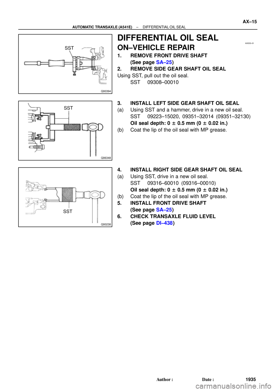
DIFFERENTIAL OIL SEAL
ON±VEHICLE REPAIR
1. REMOVE FRONT DRIVE SHAFT
(See page SA±25)
2. REMOVE SIDE GEAR SHAFT OIL SEAL
Using SST, pull out the oil seal.
SST 09308±00010
3. INSTALL LEFT SIDE GEAR SHAFT OIL SEAL
(a) Using SST and a hammer, drive in a new oil seal.
SST 09223±15020, 09351±32014 (09351±32130)
Oil seal depth: 0 ± 0.5 mm (0 ± 0.02 in.)
(b) Coat the lip of the oil seal with MP grease.
4. INSTALL RIGHT SIDE GEAR SHAFT OIL SEAL
(a) Using SST, drive in a new oil seal.
SST 09316±60010 (09316±00010)
Oil seal depth: 0 ± 0.5 mm (0 ± 0.02 in.)
(b) Coat the lip of the oil seal with MP grease.
5. INSTALL FRONT DRIVE SHAFT
(See page SA±25)
6. CHECK TRANSAXLE FLUID LEVEL
(See page DI±438)