Page 1954 of 4770
Q10027
Q10071
Q10034
Q10035
Q10040
AX±26
± AUTOMATIC TRANSAXLE (A541E)AUTOMATIC TRANSAXLE UNIT
1946 Author�: Date�:
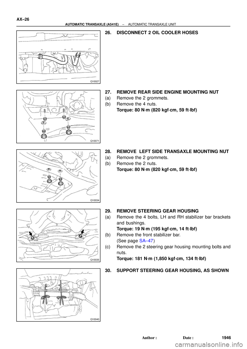
26. DISCONNECT 2 OIL COOLER HOSES
27. REMOVE REAR SIDE ENGINE MOUNTING NUT
(a) Remove the 2 grommets.
(b) Remove the 4 nuts.
Torque: 80 N´m (820 kgf´cm, 59 ft´lbf)
28. REMOVE LEFT SIDE TRANSAXLE MOUNTING NUT
(a) Remove the 2 grommets.
(b) Remove the 2 nuts.
Torque: 80 N´m (820 kgf´cm, 59 ft´lbf)
29. REMOVE STEERING GEAR HOUSING
(a) Remove the 4 bolts, LH and RH stabilizer bar brackets
and bushings.
Torque: 19 N´m (195 kgf´cm, 14 ft´lbf)
(b) Remove the front stabilizer bar.
(See page SA±47)
(c) Remove the 2 steering gear housing mounting bolts and
nuts.
Torque: 181 N´m (1,850 kgf´cm, 134 ft´lbf)
30. SUPPORT STEERING GEAR HOUSING, AS SHOWN
Page 1999 of 4770
BO0M9±01
H01782
H01783
BO±40
± BODYBODY OUTSIDE MOULDING
2388 Author�: Date�:
REMOVAL
CAUTION:
�Store in a cool place, avoiding direct sunlight, high
temperature and dust.
�The moulding is made of polyvinyl chloride. Do not al-
low this material to come in contact with thinner or
other solvents, open flame or boiling water.
�The storage time for the moulding and adhesive is
limited to about 9 months.
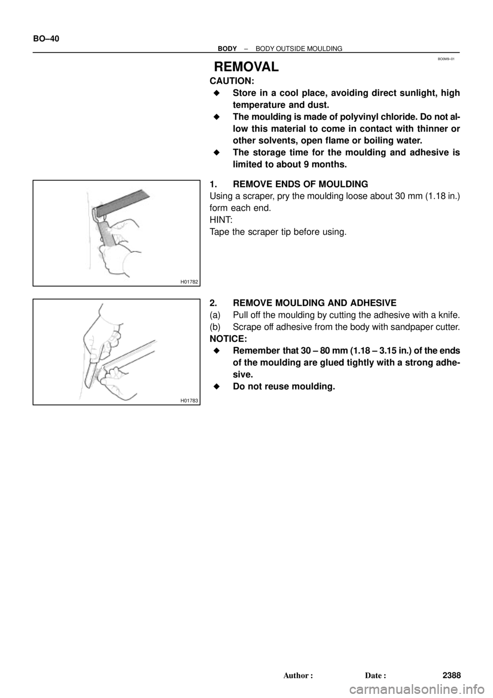
1. REMOVE ENDS OF MOULDING
Using a scraper, pry the moulding loose about 30 mm (1.18 in.)
form each end.
HINT:
Tape the scraper tip before using.
2. REMOVE MOULDING AND ADHESIVE
(a) Pull off the moulding by cutting the adhesive with a knife.
(b) Scrape off adhesive from the body with sandpaper cutter.
NOTICE:
�Remember that 30 ± 80 mm (1.18 ± 3.15 in.) of the ends
of the moulding are glued tightly with a strong adhe-
sive.
�Do not reuse moulding.
Page 2100 of 4770

BE±6
± BODY ELECTRICALBODY ELECTRICAL SYSTEM
2226 Author�: Date�:
Washer fluid does not operate.1. Washer Hose and Nozzle±
� In wiper switch HI position, the wiper blade is in contact with
the body.
� When the wiper switch is OFF, the wiper blade does not
retract or the retract position is wrong.1. *1Wiper Switch
2. Wire HarnessBE±40
±
COMBINATION METER
METER, GAUGES AND ILLUMINATION:
SymptomSuspect AreaSee page
Tachometer, Fuel Gauge and Engine Coolant Temperature Gauge
do not operate.1. GAUGE Fuse (I/P J/B No.1)
2. Meter Circuit Plate
3. Wire Harness±
BE±46
±
Speedometer does not operate.
1. No.1 Vehicle Speed Sensor
2. Meter Circuit Plate
3. Wire HarnessBE±47
BE±46
±
Tachometer does not operate.
1. Igniter (5S±FE)
(1MZ±FE)
2. Meter Circuit Plate
3. Wire HarnessIG±1
IG±1
BE±46
±
Fuel Gauge does not operate or abnormal operation.
1. Fuel Receiver Gauge
2. Fuel Sender Gauge
3. Meter Circuit Plate
4. Wire HarnessBE±47
BE±47
BE±46
±
Engine Coolant Temperature Gauge does not operate or abnormal
operation
1. Engine Coolant Temperature Receiver Gauge
2. Engine Coolant Temperature Sender Gauge
3. Meter Circuit Plate
4. Wire HarnessBE±47
BE±47
BE±46
±
All illumination lights do not light up.
1. TAIL Fuse (I/P J/B No.1)
2. Light Control Rheostat
3. Wire Harness±
BE±47
±
Brightness does not change even when rheostat turned.1. Bulb
2. Wire Harness±
±
Only one illumination light does not light up.1. Bulb
2. Wire Harness±
±
COMBINATION METER
WARNING LIGHTS:
SymptomSuspect AreaSee page
Warning lights do not light up. (Except Discharge, Open Door and
SRS)1. GAUGE Fuse (I/P J/B No.1)
2. Meter Circuit Plate
3. Wire Harness±
BE±46
±
Low Oil Pressure warning light does not light up.
1. Bulb
2. Low Oil Pressure Warning Switch
3. Meter Circuit Plate
4. Wire Harness±
BE±47
BE±46
±
Fuel Level warning light does not light up.
1. Bulb
2. Fuel Level Warning Switch
3. Meter Circuit Plate
4. Wire Harness±
BE±47
BE±46
±
ABS warning light does not light up.
1. Bulb
2. ABS ECU
3. Wire Harness±
IN±31
±
Page 2102 of 4770

(A541E)
4. Wire Harne")
BE±8
± BODY ELECTRICALBODY ELECTRICAL SYSTEM
2228 Author�: Date�:
Shift indicator lights do not light up.
1. Bulb
2. Meter Circuit Plate
3. Park/Neutral Position Switch (A140E)
(A541E)
4. Wire Harness±
BE±46
DI±424
DI±479
±
Only one shift indicator does not light up.1. Bulb
2. Meter Circuit Plate±
BE±46
Malfunction indicator light does not light up.
1. Bulb
2. ECM
3. Meter Circuit Plate
4. Wire Harness±
±
BE±46
±
SLIP indicator light does not light up.
1. Bulb
2. Traction ECU
3. Meter Circuit Plate
4. Wire Harness±
±
BE±46
±
TRAC OFF indicator light does not light up.
1. Bulb
2. Traction ECU
3. Meter Circuit Plate
4. Wire Harness±
±
BE±46
±
Security indicator light does not light up.
1. Bulb
2. Security ECU
3. Meter Circuit Plate
4. Wire Harness±
±
BE±46
±
Indicator lights do not light up. (Except Turn, Hi±beam and
security)1. GAUGE Fuse (I/P J/B No.1)
2. Wire Harness±
±
DEFOGGER SYSTEM
SymptomSuspect AreaSee page
All defogger systems do not operate.
1. DEFOG M±Fuse (I/P J/B No.1)
2. HTR Fuse (I/P J/B No.1)
3. Defogger Relay (I/P J/B No.1)
4. Defogger Switch
5. Wire Harness±
±
BE±56
BE±56
±
Rear window defogger does not operate.
1. Defogger Wire
2. Choke Coil
3. Wire HarnessBE±56
±
±
Mirror defogger does not operate.
1. MIR/HTR Fuse (I/P J/B No.1)
2. Mirror Defogger
3. Wire Harness±
BE±56
±
POWER WINDOW CONTROL SYSTEM
SymptomSuspect AreaSee page
Power window does not operate (ALL).
(Power Door Lock does not operate)1. POWER M±Fuse (I/P J/B No.1)
2. Power Main Relay (I/P J/B No.1)
3. Wire Harness±
BE±60
±
Power window does not operate (ALL).
(Power Door Lock is normal)1. Ignition Switch
2. Power Window Master Switch
3. Wire HarnessBE±14
BE±60
±
ºOne Touch Power Window Systemº does not operate.1. Power Window Master SwitchBE±60
Only one window glass does not move.
1. Power Window Master Switch
2. Power Window Switch
3. Power Window Motor
4. Wire HarnessBE±60
BE±60
BE±60
±
ºWindow Lock Systemº does not operate.1. Power Window Master SwitchBE±60
Page 2137 of 4770
N20154
2 3
4
5
N20155
1 2
12
± BODY ELECTRICALWIPER AND WASHER SYSTEM
BE±43
2263 Author�: Date�:
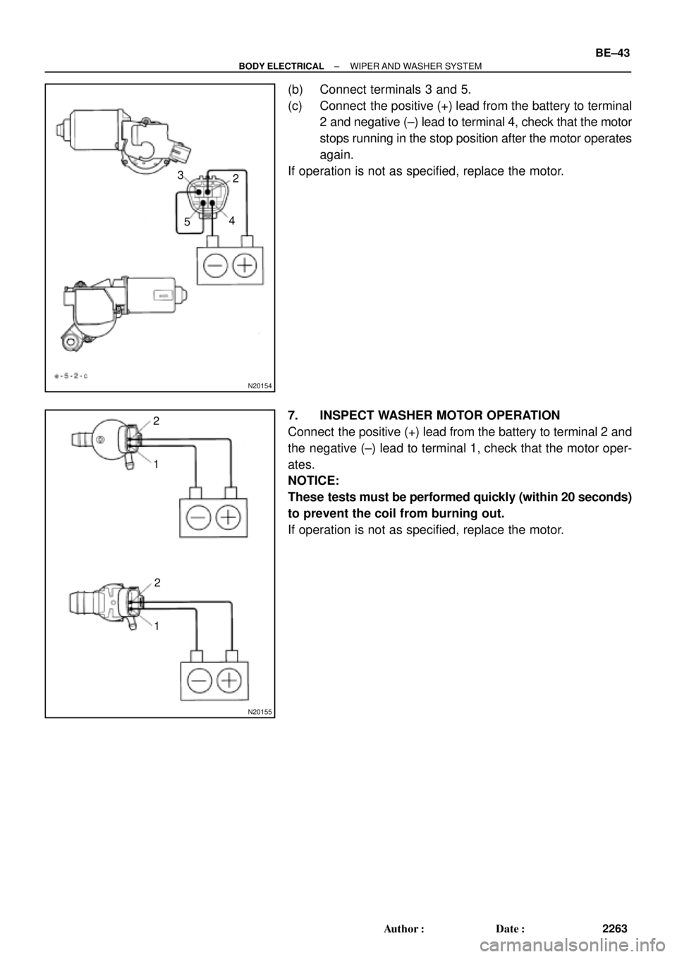
(b) Connect terminals 3 and 5.
(c) Connect the positive (+) lead from the battery to terminal
2 and negative (±) lead to terminal 4, check that the motor
stops running in the stop position after the motor operates
again.
If operation is not as specified, replace the motor.
7. INSPECT WASHER MOTOR OPERATION
Connect the positive (+) lead from the battery to terminal 2 and
the negative (±) lead to terminal 1, check that the motor oper-
ates.
NOTICE:
These tests must be performed quickly (within 20 seconds)
to prevent the coil from burning out.
If operation is not as specified, replace the motor.
Page 2139 of 4770
Z19055
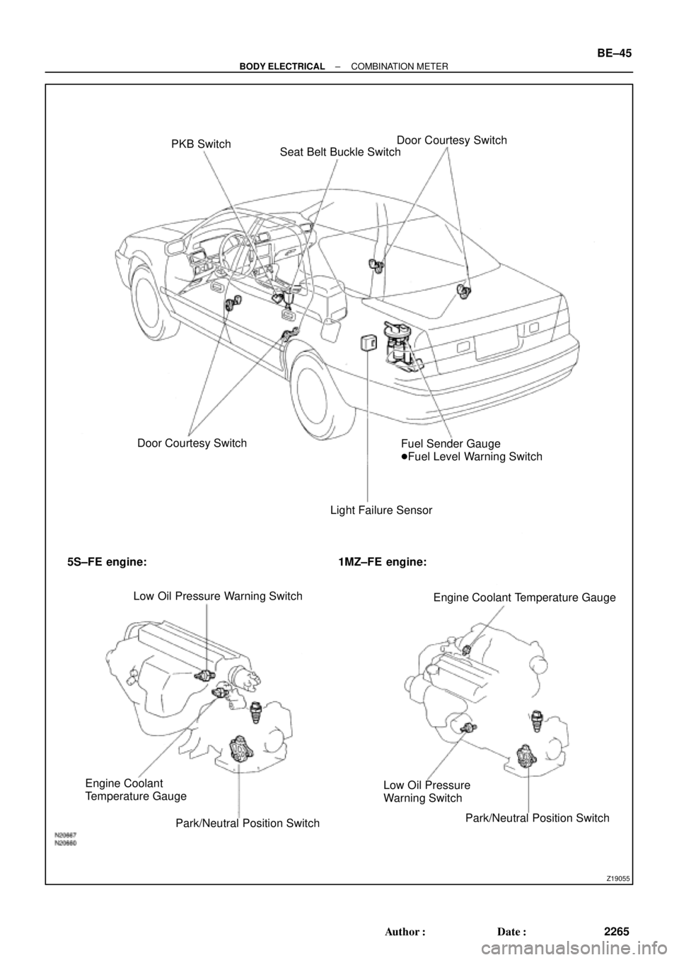
PKB Switch
Seat Belt Buckle SwitchDoor Courtesy Switch
Door Courtesy Switch
Light Failure SensorFuel Sender Gauge
�Fuel Level Warning Switch
5S±FE engine: 1MZ±FE engine:
Low Oil Pressure Warning Switch
Engine Coolant Temperature Gauge
Engine Coolant
Temperature Gauge
Park/Neutral Position SwitchLow Oil Pressure
Warning Switch
Park/Neutral Position Switch
± BODY ELECTRICALCOMBINATION METER
BE±45
2265 Author�: Date�:
Page 2140 of 4770

BE0AJ±03
Z18937
Connector ºAº Connector ºBº Connector ºCº
Connector ºAº
Connector ºBº
Connector ºCº
J±13±1±A J±16±1 J±13±1
1 2 3 4 5 6 7 8 9 10 11 12 1314 15 16 1 234 56 78 910111213 1 23456 78910111213
C7
C5
A2 B3
A1
C8
B15
C6
B6
A4
C4
B5
C10 B14
A13
B2
C1
B1
C9
A6
A11
A7
A10
A8
A9
C13
B8
B11
B12A5
C11
B4
B16 C2
A12
A3
B7
C3
C12
B9
B10
B13 F
E
T
S
ODOMETER
Fuel Level Warning
Seat Belt Warning
ABS Warning
Low Oil Pressure Warning
Cruise Control Indicator
Malfunction Indicator
O/D OFF Indicator
Light Failure Warning
Brake Warning
SLIP Indicator
TRAC Indicator
Washer Level Warning
Discharge Warning
Right Turn Indicator
Left Turn Indicator
Security Indicator
L
2
D
N
R
P
Illumination
Hi±Beam Indicator
Open Door Warning
SRS Warning
: Fuel Gauge
: Engine Coolant Temperature Gauge
: Tachometer
: Speedometer
No.
A
B
C1
2
3
4
5
6
7 8
9
10
11
12 13
14
15
16
2 3
4
5
6
7 8
9
10
11 12
131
2
3
4 5
6
7
8
9
10
11
12
13
F
E
T
SEngine coolant temperature sender gauge
Ground
Light failure sensor
Integration relay
Traction ECU
Park/neutral position switch (A/T)
O/D OFF switch (A/T)
IGN fuse
Turn signal switch
ST relay
Fuel sender gauge
Generator
Oil pressure switch
Fuel sender gauge
Parking brake switch and brake fluid level warning switch
Headlight dimmer switch
Headlight dimmer switch
Door courtesy switch
DOME fuse
ECU±B fuse
Airbag sensor assembly
ECM
No.1 Vehicle speed sensor Ground
Turn signal switch ECM
Traction ECU
ABS ECU
Ground No.1 Vehicle speed sensor
GAUGE fuse
Igniter
Security ECU
Cruise control ECU
Washer fluid level warning switch
Light control rheostat
TAIL fuse Park/neutral position switch (A/T) Park/neutral position switch (A/T) Park/neutral position switch (A/T) Park/neutral position switch (A/T)
Park/neutral position switch (A/T)Wire Harness Side
Bulb Check
Relay
N20107 N201081
BE±46
± BODY ELECTRICALCOMBINATION METER
2266 Author�: Date�:
CIRCUIT
Page 2142 of 4770
 Compare the")
N20160
Ignition
Switch
Fuel
Gauge
Battery
Z05727
Ignition
SwitchFuel
Gauge
Battery
Ie±5±1±A BE1206123
45
N20212
A
B
C BE±48
± BODY ELECTRICALCOMBINATION METER
2268 Author�: Date�:
(b) Compare the tester with tachometer indications.
DC 13.5 V 25°C at (77 °F)
Standard indicationAllowable range
700630 ± 770
1,000900 ± 1,100
2,0001,850 ± 2,150
3,0002,800 ± 3,200
4,0003,800 ± 4,200
5,0004,800 ± 5,200
6,0005,750 ± 6,250
7,0006,700 ± 7,300
4. INSPECT FUEL RECEIVER GAUGE OPERATION
(a) Disconnect the connector from the sender gauge.
(b) Turn the ignition switch ON, check that the receiver gauge
needle indicates EMPTY.
(c) Connect terminals 2 and 3 on the wire harness side con-
nector through a 3.4±W test bulb.
(d) Turn the ignition switch ON, check that the bulb lights up
and the receiver gauge needle moves towards the full
side.
HINT:
Because of the silicon oil in the gauge, it will take a short time
for needle to stabilize.
If operation is not as specified, inspect the receiver gauge resis-
tance.
5. INSPECT FUEL RECEIVER GAUGE RESISTANCE
Measure the resistance between terminals.
Tester connectionResistance (W)
A ± BApprox. 126.2
A ± CApprox. 280.5
B ± CApprox. 154.3
If resistance value is not as specified, replace the receiver
gauge.