Page 2262 of 4770

2. DISCONNECT FLEXIBLE HOSE
(a) Remove the unio")
BR0B3±03
W03263
W03264
BR±40
± BRAKEREAR BRAKE CALIPER
2063 Author�: Date�:
REMOVAL
1. REMOVE REAR WHEEL
Torque: 103 N´m (1.050 kgf´cm, 76 ft´lbf)
2. DISCONNECT FLEXIBLE HOSE
(a) Remove the union bolt and 2 gaskets from the caliper,
then disconnect the flexible hose from the caliper.
Torque: 29 N´m (300 kgf´cm, 21 ft´lbf)
HINT:
At the time of installation, please refer to the following item.
Insert the flexible hose lock securely in the lock hole in the cali-
per.
(b) Use a container to catch the brake fluid as it drains out.
3. REMOVE CALIPER
(a) Remove the installation bolt.
Torque: 20 N´m (200 kgf´cm, 14 ft´lbf)
(b) Remove the caliper from the torque plate.
4. REMOVE 2 BRAKE PADS WITH 4 ANTI±SQUEAL
SHIMS
5. REMOVE 4 PAD SUPPORT PLATES
NOTICE:
At the time of installation, please refer to the following item.
There should be no oil or grease adhering to the friction
surfaces of the pads or disc.
6. REMOVE MAIN PIN
Loosen the main pin installation bolt and remove the main pin.
Torque: 26 N´m (270 kgf´cm, 20 ft´lbf)
Page 2303 of 4770
GENERATOR
CH±9
1756 Author�: Date�:
INSPECTION
1")
CH02Y±01
CH0784
Ohmmeter
Continuity
CH0783
Ohmmeter
No Continuity
CH1023
P13482
Ohmmeter
Continuity
P13565
Ohmmeter
No Continuity
± CHARGING (5S±FE)GENERATOR
CH±9
1756 Author�: Date�:
INSPECTION
1. INSPECT ROTOR
(a) Check the rotor for open circuit.
Using an ohmmeter, check that there is continuity be-
tween the slip rings.
Standard resistance: 2.7 ± 3.1 W at 20°C (68°F)
If there is no continuity, replace the rotor.
(b) Check the rotor for ground.
Using an ohmmeter, check that there is no continuity be-
tween the slip ring and rotor.
If there is continuity, replace the rotor.
(c) Check that the slip rings are not rough or scored.
If rough or scored, replace the rotor.
(d) Using vernier calipers, measure the slip ring diameter.
Standard diameter: 14.2 ± 14.4 mm (0.559 ± 0.567 in.)
Minimum diameter: 12.8 mm (0.504 in.)
If the diameter is less than minimum, replace the rotor.
2. INSPECT STATOR (DRIVE END FRAME)
(a) Check the stator for open circuit.
Using an ohmmeter, check that there is continuity be-
tween the coil leads.
If there is no continuity, replace the drive end frame assembly.
(b) Check the stator for ground.
Using an ohmmeter, check that there is no continuity be-
tween the coil lead and drive end frame.
If there is continuity, replace the drive end frame assembly.
Page 2319 of 4770
GENERATOR
CH±9
1772 Author�: Date�:
INSPECTION
1. IN")
CH01H±01
CH0784
Ohmmeter
Continuity
CH0783
Ohmmeter
No Continuity
CH0192
P00484
OhmmeterContinuity
P00482
OhmmeterContinuity
± CHARGING (1MZ±FE)GENERATOR
CH±9
1772 Author�: Date�:
INSPECTION
1. INSPECT ROTOR
(a) Check the rotor for open circuit.
Using an ohmmeter, check that there is continuity be-
tween the slip rings.
Standard resistance: 2.1 ± 2.5 W at 20°C (68°F)
If there is no continuity, replace the rotor.
(b) Check the rotor for ground.
Using an ohmmeter, check that there is no continuity be-
tween the slip ring and rotor.
If there is continuity, replace the rotor.
(c) Check that the slip rings are not rough or scored.
If rough or scored, replace the rotor.
(d) Using vernier calipers, measure the slip ring diameter.
Standard diameter: 14.2 ± 14.4 mm (0.559±0.567 in.)
Minimum diameter: 12.8 mm (0.504 in.)
If the diameter is less than minimum, replace the rotor.
2. INSPECT STATOR (DRIVE END FRAME)
(a) Check the stator for open circuit.
Using an ohmmeter, check that there is continuity be-
tween the coil leads.
If there is no continuity, replace the drive end frame assembly.
(b) Check the stator for ground.
Using an ohmmeter, check that there is no continuity be-
tween the coil lead and drive end frame.
If there is continuity, replace the drive end frame assembly.
Page 2327 of 4770

CL034±01
± CLUTCHTROUBLESHOOTING
CL±1
1780 Author�: Date�:
TROUBLESHOOTING
PROBLEM SYMPTOMS TABLE
Use the table below to help you find the cause of the problem. The numbers indicate the priority of the likely
cause of the problem. Check each part in order. If necessary, replace these parts.
SymptomSuspect AreaSee page
1. Engine mounting (Loosen)±1. Engine mounting (Loosen)
2. Clutch disc (Runout is excessive)
±
CL±17
2. Clutch disc (Runout is excessive)
3. Clutch disc (Oily)
CL±17
CL±17
Clutch grabs/chatters
3. Clutch disc (Oily)
4. Clutch disc (Worn out)
CL±17
CL±17Clutch grabs/chatters4. Clutch disc (Worn out)
5. Clutch disc torsion rubber (Damaged)
CL±17
CL±175. Clutch disc torsion rubber (Damaged)
6. Clutch disc (Glazed)
CL 17
CL±176. Clutch disc (Glazed)
7. Diaphragm spring (Out of tip alignment)
CL 17
CL±19
1. Clutch line (Air in line)±
Clutch pedal spongy
1. Clutch line (Air in line)
2. Master cylinder cup (Damaged)
±
CL±4
Clutch edal s ongy2. Master cylinder cu (Damaged)
3. Release cylinder cup (Damaged)
CL 4
CL±9
1 Release bearing (Worn dirty or damaged)CL 19Clutch noisy1. Release bearing (Worn, dirty, or damaged)
2Cl hdi i bb (D d)
CL±19
CL 17Clutch noisy2. Clutch disc torsion rubber (Damaged)CL±17
1. Clutch pedal (Freeplay out of adjustment)CL±21. Clutch edal (Free lay out of adjustment)
2. Clutch disc (Oily)
CL±2
CL±17
Cl t h li
2. Clutch disc (Oily)
3. Clutch disc (Worn out)
CL±17
CL±17Clutch slips3. Clutch disc (Worn out)
4. Diaphragm spring (Damaged)
CL 17
CL±174. Dia hragm s ring (Damaged)
5. Pressure plate (Distortion)
CL 17
CL±175. Pressure late (Distortion)
6. Flywheel (Distortion)
CL 17
±
1 Clutchpedal (Freeplay out of adjustment)CL±21. Clutch pedal (Freeplay out of adjustment)
2 Clutch line (Air in line)CL±2
2. Clutch line (Air in line)
3 Master cylinder cup(Damaged)
±
CL 43. Master cylinder cup (Damaged)
4 Release cylinder cup(Damaged)
CL±4
CL 94. Release cylinder cup (Damaged)
5 Clutch disc (out of true)
CL±9
CL 175. Clutch disc (out of true)
6 Cl tch disc (R no t is e cessi e)
CL±17
CL 17
Cl t h d t di
6. Clutch disc (Runout is excessive)
7 Cl t h di (Li i b k )
CL±17
CL 17Clutch does not disengage7. Clutch disc (Lining broken)
8 Cl t h di (Di t b d)
CL±17
CL 178. Clutch disc (Dirty or burned)
Cl h di (Oil )
CL±17
CL9. Clutch disc (Oily)CL±17
10. Clutch disc (Lack of spline grease)CL±19
11. Diaphragm spring (Damaged)CL±17gg(g)
12. Diaphragm spring (Out of tip alignment)CL±19gg( g)
13. Pressure plate (Distortion)CL±17
Page 2349 of 4770
CO066±03
± COOLING (5S±FE)COOLANT
CO±1
1575 Author�: Date�:
COOLANT
INSPECTION
HINT:
Check the coolant level when the engine is cold.
1. CHECK ENGINE COOLANT LEVEL AT RADIATOR RESERVOIR
The engine coolant level should be between the ºLOWº and ºFULLº lines.
If low, check for leaks and add ºToyota Long Life Coolantº or equivalent up to the ºFULLº line.
2. CHECK ENGINE COOLANT QUALITY
(a) Remove the radiator cap.
CAUTION:
To avoid the danger of being burned, do not remove the radiator cap while the engine and radiator
are still hot, as fluid and steam can be blown out under pressure.
(b) There should not be any excessive deposits of rust or scale around the radiator cap or radiator filler
hole, and the coolant should be free from oil.
If excessively dirty, replace the coolant.
(c) Reinstall the radiator cap.
Page 2350 of 4770
COOLANT
1576 Author�: Date�:
REPLACEMENT
1. DRAIN ENGINE COOLANT
(a) Remove the radiator cap.
CAUTION:
To avoid the dang")
CO067±03
Z18990
Radiator Drain Plug
Engine Drain Plug CO±2
± COOLING (5S±FE)COOLANT
1576 Author�: Date�:
REPLACEMENT
1. DRAIN ENGINE COOLANT
(a) Remove the radiator cap.
CAUTION:
To avoid the danger of being burned, do not remove the ra-
diator cap while the engine and radiator are still hot, as fluid
and steam can be blown out under pressure.
(b) Loosen the radiator drain plug (on the right side of the ra-
diator lower tank) and engine drain plug (on the left rear
of the cylinder block), and drain the coolant.
(c) Close the drain plugs.
Torque: 25 N´m (250 kgf´cm, 18 ft´lbf) for engine
2. FILL ENGINE COOLANT
(a) Slowly fill the system with coolant.
�Use of improper coolants may damage engine cool-
ing system.
�Use ºToyota Long Life Coolantº or equivalent and
mix it with plan water according to the manufactur-
er's directions.
�Using of coolant which includes more than 50 %
(freezing protection down to ±35°C (±31°F) or 60 %
(freezing protection down to ±50°C (±58°F)) of eth-
ylene±glycol is recommended but not more than 70
%.
NOTICE:
�Do not use an alcohol type coolant or plain water
alone.
�The coolant should be mixed with plain water (prefer-
ably demineralized water or distilled water).
Capacity:
w/ Oil cooler6.9 litters (7.3 US qts, 6.1 lmp. qts)
w/o Oil cooler6.2 litters (6.5 US qts, 5.4 lmp. qts)
(b) Install the radiator cap.
(c) Start the engine, and bleed the cooling system.
(d) Refill the radiator reservoir with coolant until it reaches the
ºFULLº line.
3. CHECK FOR COOLANT LEAKS
Page 2351 of 4770
CO068±03
S05543
Engine Moving Control Rod
No.2 RH Engine Mounting Bracket
Generator Drive Belt
w/ Oil Cooler
A/C Compressor
Connector
A/C Compressor
Cylinder Block Insulator
N´m (kgf´cm, ft´lbf)RH Front Fender Apron SealPS Pump Drive BeltGround Strap Connector
: Specified torque
64 (650, 47)
64 (650, 47)
52 (530, 38)
± COOLING (5S±FE)WATER PUMP
CO±3
1577 Author�: Date�:
WATER PUMP
COMPONENTS
Page 2353 of 4770
CO069±04
S05599
S05924
S05963
1
2
3
± COOLING (5S±FE)WATER PUMP
CO±5
1579 Author�: Date�:
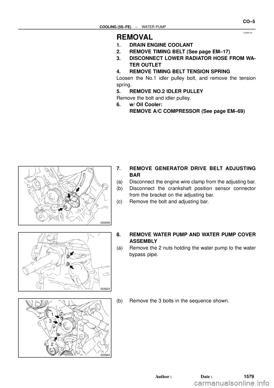
REMOVAL
1. DRAIN ENGINE COOLANT
2. REMOVE TIMING BELT (See page EM±17)
3. DISCONNECT LOWER RADIATOR HOSE FROM WA-
TER OUTLET
4. REMOVE TIMING BELT TENSION SPRING
Loosen the No.1 idler pulley bolt, and remove the tension
spring.
5. REMOVE NO.2 IDLER PULLEY
Remove the bolt and idler pulley.
6. w/ Oil Cooler:
REMOVE A/C COMPRESSOR (See page EM±69)
7. REMOVE GENERATOR DRIVE BELT ADJUSTING
BAR
(a) Disconnect the engine wire clamp from the adjusting bar.
(b) Disconnect the crankshaft position sensor connector
from the bracket on the adjusting bar.
(c) Remove the bolt and adjusting bar.
8. REMOVE WATER PUMP AND WATER PUMP COVER
ASSEMBLY
(a) Remove the 2 nuts holding the water pump to the water
bypass pipe.
(b) Remove the 3 bolts in the sequence shown.

RH")