Page 4708 of 4770

TRANSMISSION OIL COOLER INSTALLATION ± TC003±97 October 17, 1997
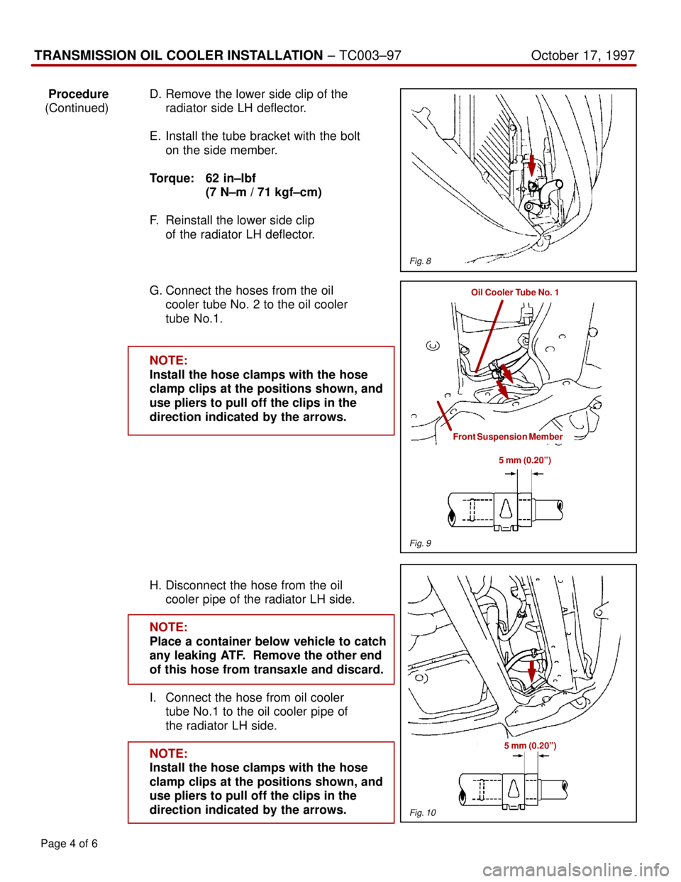
ProcedureD. Remove the lower side clip of the
(Continued) radiator side LH deflector.
E. Install the tube bracket with the bolt
on the side member.
Torque: 62 in±lbf
(7 N±m / 71 kgf±cm)
F. Reinstall the lower side clip
of the radiator LH deflector.
G. Connect the hoses from the oil
cooler tube No. 2 to the oil cooler
tube No.1.
NOTE:
Install the hose clamps with the hose
clamp clips at the positions shown, and
use pliers to pull off the clips in the
direction indicated by the arrows.
H. Disconnect the hose from the oil
cooler pipe of the radiator LH side.
NOTE:
Place a container below vehicle to catch
any leaking ATF. Remove the other end
of this hose from transaxle and discard.
I. Connect the hose from oil cooler
tube No.1 to the oil cooler pipe of
the radiator LH side.
NOTE:
Install the hose clamps with the hose
clamp clips at the positions shown, and
use pliers to pull off the clips in the
direction indicated by the arrows.
Page 4 of 6
Fig. 8
Oil Cooler Tube No. 1
Front Suspension Member
5 mm (0.20º)
Fig. 9
Fig. 10
5 mm (0.20º)
Page 4709 of 4770
Page 5 of 6
TRANSMISSION OIL COOLER INSTALLATION ± TC003±97 October 17, 1997
ProcedureJ. Install the 190 mm (7.48º) hose
(Continued) between the oil cooler tube No.1
and transaxle oil cooler tube.
NOTE:
Install the hose clamps with the hose
clamp clips at the positions shown, and
use pliers to pull off the clips in the
direction indicated by the arrows.
K. Install the oil cooler onto the center
brace and front cross member
using the two bolts and nut as
illustrated in figure 12.
Torque: 65.5 in±lbf
(7.4 N±m/75.5 kgf±cm)
L. Connect the hoses to the pipes.
NOTE:
Install the hose clamps with the hose
clamp clips at the positions shown, and
use pliers to pull off the clips in the
direction indicated by the arrows.
Fig. 11
5 mm (0.20º)
190 mm Hose
5 mm (0.20º) Oil Cooler Tube No. 1
Fig. 13
Page 4710 of 4770

TRANSMISSION OIL COOLER INSTALLATION ± TC003±97 October 17, 1997
Procedure3. Final Assembly:
(Continued)
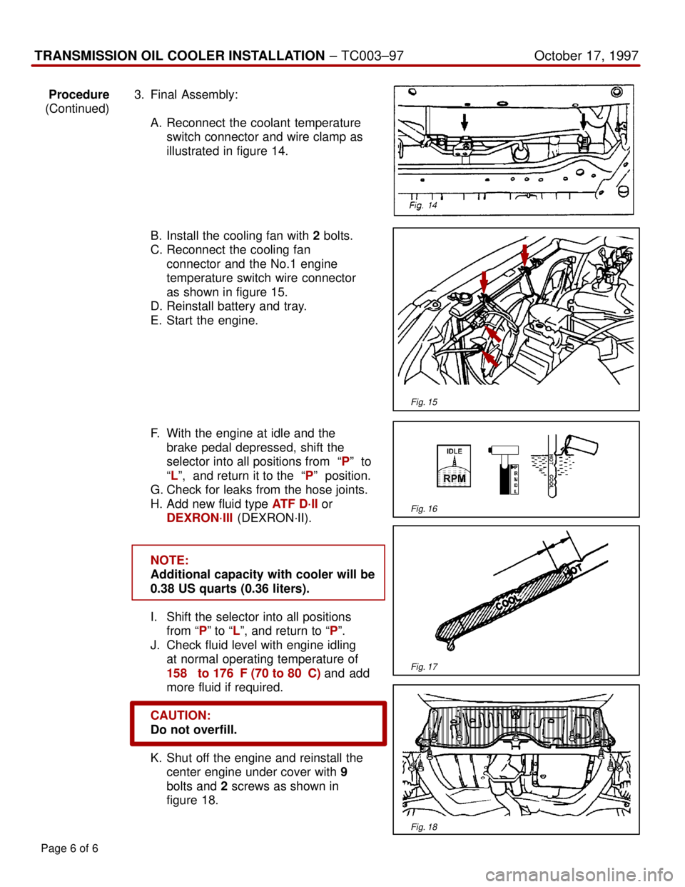
A. Reconnect the coolant temperature
switch connector and wire clamp as
illustrated in figure 14.
B. Install the cooling fan with 2 bolts.
C. Reconnect the cooling fan
connector and the No.1 engine
temperature switch wire connector
as shown in figure 15.
D. Reinstall battery and tray.
E. Start the engine.
F. With the engine at idle and the
brake pedal depressed, shift the
selector into all positions from ªPº to
ªLº, and return it to the ªPº position.
G. Check for leaks from the hose joints.
H. Add new fluid type ATF D´II or
DEXRON´III (DEXRON´II).
NOTE:
Additional capacity with cooler will be
0.38 US quarts (0.36 liters).
I. Shift the selector into all positions
from ªPº to ªLº, and return to ªPº.
J. Check fluid level with engine idling
at normal operating temperature of
158� to 176�F (70 to 80�C) and add
more fluid if required.
CAUTION:
Do not overfill.
K. Shut off the engine and reinstall the
center engine under cover with 9
bolts and 2 screws as shown in
figure 18.
Page 6 of 6
Fig. 15
Fig. 16
Fig. 17
Fig. 18
Page 4763 of 4770

Toyota Supports ASE CertificationPage 1 of 3
EG008-04Title:
M.I.L. ON" 1MZ-FE ENGINE MISFIRE
DTC P0300, P0301, P0302, P0303,
P0304, P0305 OR P0306
Models:
Applicable Avalon, Camry, Sienna & Solara
Technical Service
BULLETIN
April 28, 2004
Some vehicles equipped with 1MZ±FE (V6) engines without VVTi may exhibit a rough
idle and/or a M.I.L. ªONº condition with a diagnostic trouble code or codes for misfire
caused by an improperly operating ignition coil assembly. Production changes have been
implemented to prevent this condition from occuring.
�2001 model year Japan built Camry vehicles equipped with 1MZ±FE engines (V6).
�1998±2001 model year North American built Camry vehicles equipped with
1MZ±FE engines (V6)
�1998 ± 1999 model year Avalon vehicles.
�1998 ± 2000 model year Sienna vehicles.
�1999 ± 2002 model year Solara vehicles equipped with 1MZ±FE engines produced
BEFORE the Production Change Effective VIN shown below.
MODELENGINEPRODUCTION CHANGE EFFECTIVE VIN
Solara1MZ±FE2T1CF2#P*2C578710
OP CODEMODELDESCRIPTIONTIMEOFPT1T2
191011AvalonR & R Ignition Coil (one coil)0.290080±190120273
191011
Camry
SolaraR & R Ignition Coil (one coil)0390080 190120273191011Solara
SiennaR & R Ignition Coil (one coil)0.390080±190120273
Applicable Warranty*:
This repair is covered under the Toyota Federal Emissions Warranty. This warranty is
in effect for 36 months or 36,000 miles, whichever occurs first, from the vehicle's
in-service date.
For California specification vehicles registered and operated in California, Maine,
Massachusetts or Vermont, this repair is covered under the California Emissions
Warranty, which is in effect for 36 months or 50,000 miles, whichever occurs first, from
the vehicle's in-service date.
* Warranty application is limited to correction of a problem based upon a customer's specific complaint.
ENGINE
Introduction
Applicable
Vehicles
Production
Change
Information
Warranty
Information
Page 4764 of 4770

M.I.L. ªONº 1MZ±FE ENGINE MISFIRE DTC P0300 ± P0306 ± EG008-04April 28, 2004
Page 2 of 3
PREVIOUS PART NUMBERCURRENT PART NUMBERPART NAMEQTY
90080±19012SameIgnition Coil Assembly1
SPECIAL SERVICE TOOLS (SSTs)PART NUMBERQUANTITY
Toyota Diagnostic Tester Kit*
010012711
12 Megabyte Diagnostic Tester Program Card
with version 10.2a Software (or later)*01002593-0051
* Essential SSTs.
NOTE:
Additional Diagnostic Tester Kits, Program Cards or other SSTs may be ordered by
calling SPX/OTC at 1-800-933-8335.
TOOLS & MATERIALQUANTITY
Digital Volt Ohmmeter (DVOM)1
1. Confirm if vehicle is currently misfiring, running rough or hesitating.
If YES ± Go to Step 2.
If NO ± Review Freeze Frame Data and attempt to operate vehicle under similar
driving conditions ± see notes below for information that makes it more likely to
duplicate misfire.
NOTE:
The following activities will turn off misfire detection:
�Changing engine RPM greater than 150 RPM.
�Changing throttle position quickly.
Misfire duplication can be duplicated most readily when the engine speed and throttle
angle are held nearly constant for at least 2 minutes.
A
IGNITION 41
CYL #1 0%
CYL #2 0%
CYL #3 0%
CYL #4 Above 50%
CYL #5 0%
CYL #6 0%
MISFIRE RPM 0rpm
MISFIRE LOAD 0.00g/rev
# CODES 1
CHECK MODE OFF
MISFIRE TEST COMPL
B
IGNITION 205
CYL #1 0%
CYL #2 0%
CYL #3 0%
CYL #4 Above 50%
CYL #5 0%
CYL #6 0%
MISFIRE RPM 0rpm
MISFIRE LOAD 0.00g/rev
# CODES 1
CHECK MODE OFF
MISFIRE TEST COMPL
NOTE:
When misfire monitor is active, ignition value will change on Data List.
When pending misfire DTC is set, ªMISFIRE RPMº and ªMISFIRE LOADº will show values.
Values Will Change
From Zero
Parts
Information
Required
SSTs
Required
Tools &
Material
Repair
Procedure
Page 4765 of 4770

M.I.L. ªONº 1MZ±FE ENGINE MISFIRE DTC P0300 ± P0306 ± EG008-04April 28, 2004
Page 3 of 3
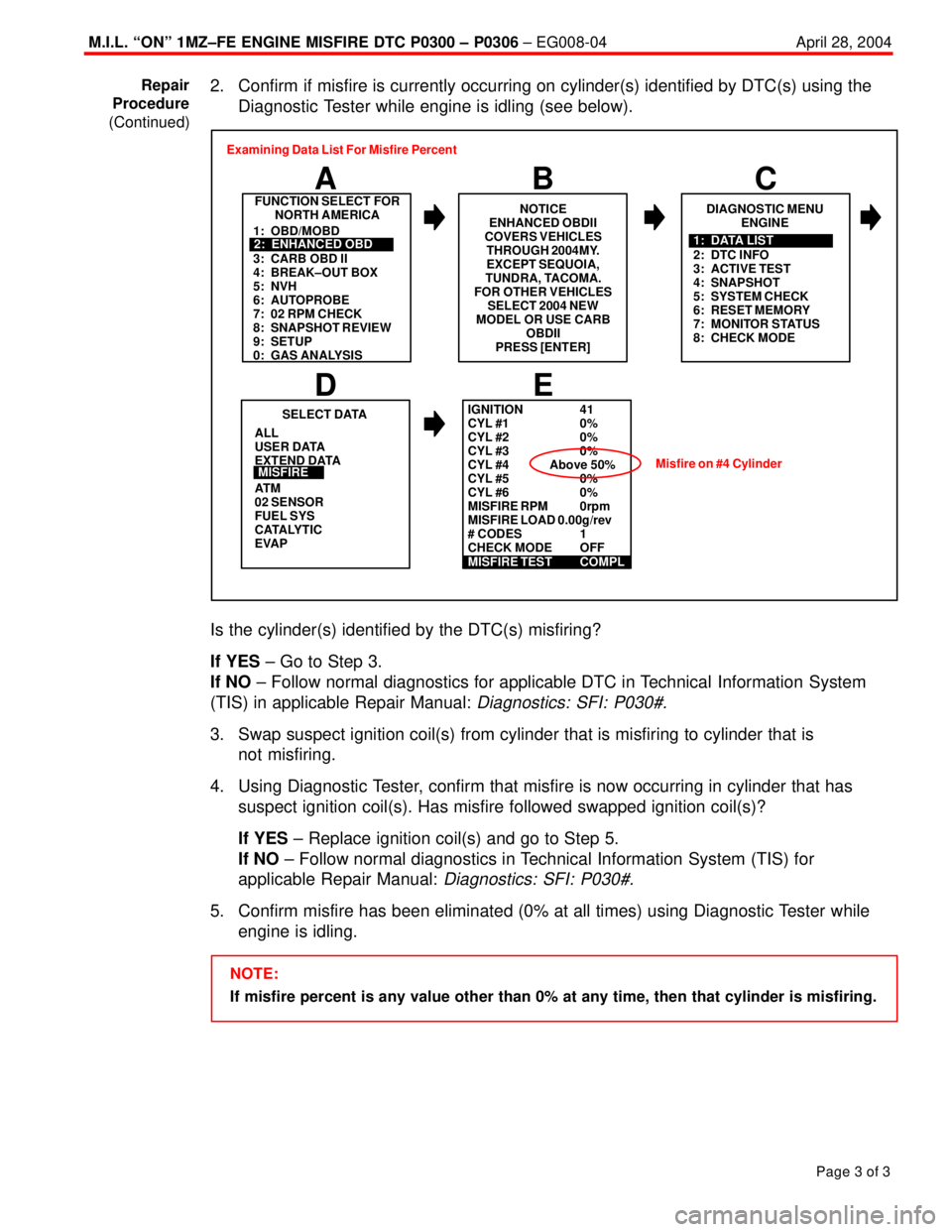
2. Confirm if misfire is currently occurring on cylinder(s) identified by DTC(s) using the
Diagnostic Tester while engine is idling (see below).
FUNCTION SELECT FOR
NORTH AMERICA
B A
DIAGNOSTIC MENU
ENGINE
C
ALL
USER DATA
EXTEND DATA
AT M
02 SENSOR
FUEL SYS
CATALYTIC
EVAP
E
SELECT DATA
D
MISFIRE
1: OBD/MOBD
3: CARB OBD II
4: BREAK±OUT BOX
5: NVH
6: AUTOPROBE
7: 02 RPM CHECK
8: SNAPSHOT REVIEW
9: SETUP
0: GAS ANALYSIS2: ENHANCED OBD
2: DTC INFO
3: ACTIVE TEST
4: SNAPSHOT
5: SYSTEM CHECK
6: RESET MEMORY
7: MONITOR STATUS
8: CHECK MODE1: DATA LIST Examining Data List For Misfire Percent
NOTICE
ENHANCED OBDII
COVERS VEHICLES
THROUGH 2004MY.
EXCEPT SEQUOIA,
TUNDRA, TACOMA.
FOR OTHER VEHICLES
SELECT 2004 NEW
MODEL OR USE CARB
OBDII
PRESS [ENTER]
IGNITION 41
CYL #1 0%
CYL #2 0%
CYL #3 0%
CYL #4 Above 50%
CYL #5 0%
CYL #6 0%
MISFIRE RPM 0rpm
MISFIRE LOAD 0.00g/rev
# CODES 1
CHECK MODE OFF
MISFIRE TEST COMPL
Misfire on #4 Cylinder
Is the cylinder(s) identified by the DTC(s) misfiring?
If YES ± Go to Step 3.
If NO ± Follow normal diagnostics for applicable DTC in Technical Information System
(TIS) in applicable Repair Manual:
Diagnostics: SFI: P030#.
3. Swap suspect ignition coil(s) from cylinder that is misfiring to cylinder that is
not misfiring.
4. Using Diagnostic Tester, confirm that misfire is now occurring in cylinder that has
suspect ignition coil(s). Has misfire followed swapped ignition coil(s)?
If YES ± Replace ignition coil(s) and go to Step 5.
If NO ± Follow normal diagnostics in Technical Information System (TIS) for
applicable Repair Manual:
Diagnostics: SFI: P030#.
5. Confirm misfire has been eliminated (0% at all times) using Diagnostic Tester while
engine is idling.
NOTE:
If misfire percent is any value other than 0% at any time, then that cylinder is misfiring. Repair
Procedure
(Continued)