Page 4659 of 4770

SUSPENSION BALL JOINT INSPECTION ± PG027-02December 4, 2002
Page 7 of 8
2. Inspect Upper Ball Joint Free Play
A. Move the upper arm by hand
(models with the LOWER control
arm linked by a torsion bar, and
all models using a coil spring).
a. Remove the front tire.
b. Inspect the free play while
moving the upper arm up and
down at a force of 67 lbf
(294 N, 30 kgf).
B. Move the tire with a lever (models
with the UPPER control arm
linked by a torsion bar).
a. Lift up the vehicle.
b. Place the lever under the tire,
and inspect the free play while
lifting the tire using a wooden
stick, etc., as a fulcrum.
3. Inspect the Suspension Arm Ball
Joint Free Play
A. Lift up the vehicle.
B. Inspect the free play while moving
the control arm by hand.
(Reference)
Free Play Inspection Method
(Gauge Installation)
�Position the dial gauge between the
arm (upper or lower) and the knuckle,
and measure free play.
(This illustration shows how to
measure free play for vehicles with
double wishbone type suspension
with coil spring.)
4. Inspect Ball Joint Dust Cover
Check for cracks and grease leaks on
the dust cover (boots).On±Vehicle
Inspection
(Continued)
Page 4690 of 4770
TOYOTA MOTOR SALES U.S.A., INC.
Beginning in 1996, Toyota will be standardizing the size of many of its oil filters to the three inch
industry standard. This new filter size is slightly larger than the existing 75mm diameter filter
presently used on many Toyota models. This larger filter will require a three inch oil filter wrench
for easy removal.
Three inch oil filter wrenches are readily available from parts stores and tool dealers, however, for
your convenience, OTC will make this new filter wrench available under P/N 00002±17001. Dealer
cost is $5.75. To order, please call OTC at 1±800±933±8335.
NEW OIL FILTER WRENCHPage 1 of 1
NOVEMBER 10, 1995
SPECIAL SERVICE
TOOLS
SS95±004
ALL MODELS
Page 4698 of 4770

Toyota Supports ASE CertificationPage 1 of 1
SU001±00Title:
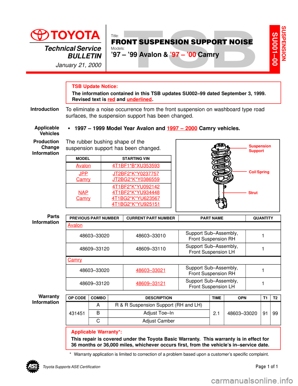
FRONT SUSPENSION SUPPORT NOISE
Models:
'97 ± '99 Avalon & '97 ± '00 Camry
Technical Service
BULLETIN
January 21, 2000
TSB Update Notice:
The information contained in this TSB updates SU002±99 dated September 3, 1999.
Revised text is red
and underlined.
To eliminate a noise occurrence from the front suspension on washboard type road
surfaces, the suspension support has been changed.
�1997 ± 1999 Model Year Avalon and 1997 ± 2000
Camry vehicles.
The rubber bushing shape of the
suspension support has been changed.
MODELSTARTING VIN
Avalon4T1BF1*B*XU353593
JPP
Camry
JT2BF2*K*Y0237757
JT2BG2*K*Y0386559
NAP
Camry
4T1BF2*K*YU092142
4T1BF2*K*YU934448
4T1BG2*K*YU623567
4T1BG2*K*YU925151
PREVIOUS PART NUMBERCURRENT PART NUMBERPART NAMEQUANTITY
Avalon
48603±3302048603±33010Support Sub±Assembly,
Front Suspension RH1
48609±3312048609±33110Support Sub±Assembly,
Front Suspension LH1
Camry
48603±3302048603±33021Support Sub±Assembly,
Front Suspension RH1
48609±3312048609±33121Support Sub±Assembly,
Front Suspension LH1
OP CODECOMBODESCRIPTIONTIMEOPNT1T2
AR & R Suspension Support (RH and LH)
431451BAdjust Toe±In2.148603±330209199
CAdjust Camber
Applicable Warranty*:
This repair is covered under the Toyota Basic Warranty. This warranty is in effect for
36 months or 36,000 miles, whichever occurs first, from the vehicle's in±service date.
* Warranty application is limited to correction of a problem based upon a customer's specific complaint.
SUSPENSION
Introduction
Applicable
Vehicles
Production
Change
Information
Suspension
Support
Coil Spring
Strut
Parts
Information
Warranty
Information
Page 4701 of 4770

Toyota Supports ASE CertificationPage 1 of 1
SU002±99Title:
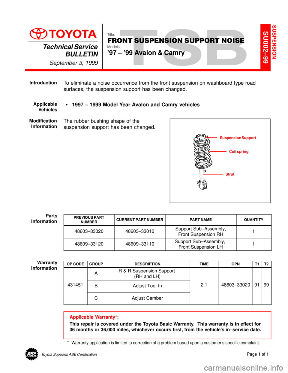
FRONT SUSPENSION SUPPORT NOISE
Models:
'97 ± '99 Avalon & Camry
Technical Service
BULLETIN
September 3, 1999
To eliminate a noise occurrence from the front suspension on washboard type road
surfaces, the suspension support has been changed.
�1997 ± 1999 Model Year Avalon and Camry vehicles
The rubber bushing shape of the
suspension support has been changed.
PREVIOUS PART
NUMBERCURRENT PART NUMBERPART NAMEQUANTITY
48603±3302048603±33010Support Sub±Assembly,
Front Suspension RH1
48609±3312048609±33110Support Sub±Assembly,
Front Suspension LH1
OP CODEGROUPDESCRIPTIONTIMEOPNT1T2
AR & R Suspension Support
(RH and LH)
431451BAdjust Toe±In2.148603±330209199
CAdjust Camber
Applicable Warranty*:
This repair is covered under the Toyota Basic Warranty. This warranty is in effect for
36 months or 36,000 miles, whichever occurs first, from the vehicle's in±service date.
* Warranty application is limited to correction of a problem based upon a customer's specific complaint.
SUSPENSION
Introduction
Applicable
Vehicles
Modification
Information
Suspension Support
Coil spring
Strut
Parts
Information
Warranty
Information
Page 4702 of 4770

Toyota Supports ASE CertificationPage 1 of 1
SU002±00Title:
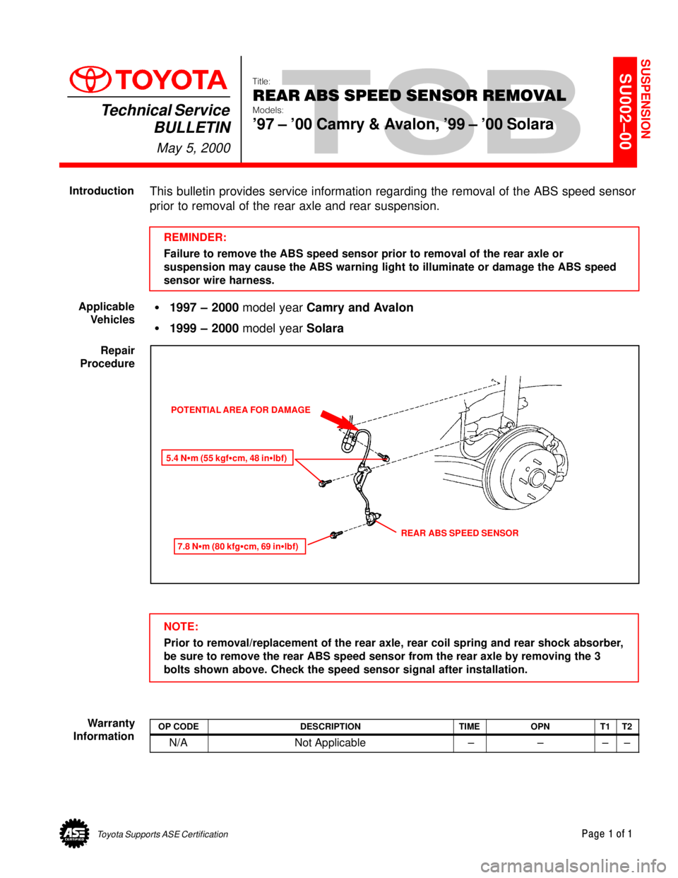
REAR ABS SPEED SENSOR REMOVAL
Models:
'97 ± '00 Camry & Avalon, '99 ± '00 Solara
Technical Service
BULLETIN
May 5, 2000
This bulletin provides service information regarding the removal of the ABS speed sensor
prior to removal of the rear axle and rear suspension.
REMINDER:
Failure to remove the ABS speed sensor prior to removal of the rear axle or
suspension may cause the ABS warning light to illuminate or damage the ABS speed
sensor wire harness.
�1997 ± 2000 model year Camry and Avalon
�1999 ± 2000 model year Solara
POTENTIAL AREA FOR DAMAGE
5.4 N�m (55 kgf�cm, 48 in�lbf)
7.8 N�m (80 kfg�cm, 69 in�lbf)
REAR ABS SPEED SENSOR
NOTE:
Prior to removal/replacement of the rear axle, rear coil spring and rear shock absorber,
be sure to remove the rear ABS speed sensor from the rear axle by removing the 3
bolts shown above. Check the speed sensor signal after installation.
OP CODEDESCRIPTIONTIMEOPNT1T2
N/ANot Applicable ±±±±
SUSPENSION
Introduction
Applicable
Vehicles
Repair
Procedure
Warranty
Information
Page 4705 of 4770

TSB
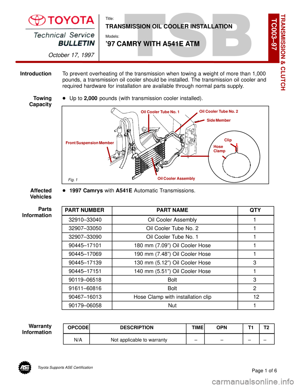
IntroductionTo prevent overheating of the transmission when towing a weight of more than 1,000
pounds, a transmission oil cooler should be installed. The transmission oil cooler and
required hardware for installation are available through normal parts supply.
Towing�Up to 2,000 pounds (with transmission cooler installed).
Capacity
Affected�1997 Camrys with A541E Automatic Transmissions.
Vehicles
Parts
Information
Warranty
Information
TRANSMISSION & CLUTCH
October 17, 1997
Title:
TRANSMISSION OIL COOLER INSTALLATION
Models:
'97 CAMRY WITH A541E ATM
Page 1 of 6
TC003±97
Clip
Hose
Clamp
Oil Cooler Assembly
Front Suspension Member
Oil Cooler Tube No. 1Oil Cooler Tube No. 2
Side Member
PART NUMBER PART NAME QTY
32910±33040 Oil Cooler Assembly 1
32907±33050 Oil Cooler Tube No. 2 1
32907±33090 Oil Cooler Tube No. 1 1
90445±17101 180 mm (7.09º) Oil Cooler Hose 1
90445±17069 190 mm (7.48º) Oil Cooler Hose 1
90445±17139 130 mm (5.12º) Oil Cooler Hose 3
90445±17151 140 mm (5.51º) Oil Cooler Hose 1
90119±06518 Bolt 3
91611±60816 Bolt 2
90467±16013 Hose Clamp with installation clip 12
90179±06058 Nut 1
OPCODE DESCRIPTION TIME OPN T1 T2
N/A Not applicable to warranty ± ± ± ±
Fig. 1
Toyota Supports ASE Certification
Page 4706 of 4770
TRANSMISSION OIL COOLER INSTALLATION ± TC003±97 October 17, 1997
Procedure1. Parts removal in preparation for cooler
installation:
A. Remove the 9 bolts, 2 screws and
the center engine under cover.
B. Remove the engine coolant
temperature switch connector and
the wire clamp.
C. Remove battery and tray.
D. Disconnect the cooling fan
connector.
E. Disconnect the No.1 engine coolant
temperature switch wire connector.
F. Remove the 2 bolts and then the
cooling fan.
Page 2 of 6
Fig. 2Center Engine Under Cover
Fig. 3ClampSwitch
Fig. 4
Page 4707 of 4770
Page 3 of 6
TRANSMISSION OIL COOLER INSTALLATION ± TC003±97 October 17, 1997
Procedure2. Cooler Installation:
(Continued)
A. Install the 140 mm (5.51º) hose to
the oil cooler tube No. 1 as shown.
NOTE:
Install the hose clamp with the hose
clamp clip at the position shown, and
use pliers to pull off the clip in the
direction indicated by the arrow.
B. Install the tube bracket onto the left
side of the front suspension
member with the 2 bolts as shown.
Torque: 62 in±lbf
(7 N±m / 71 kgf±cm)
C. Install the 130 mm (5.12º) hoses
and the 180 mm (7.09º) hose to the
oil cooler tube No. 2 as shown.
NOTE:
Install the hose clamps with the hose
clamp clips at the positions shown,
and use pliers to pull off the clips in
the direction indicated by the arrows.
Fig. 5
Oil Cooler Tube No. 1
140 mm Hose
5 mm (0.20º)
Fig. 6
Fig. 7
5 mm (0.20º)
180 mm Hose Oil Cooler Tube No. 2
130 mm Hose