Page 4380 of 4770
SA07T±04
F06530
Suspension Support
Spring Bumper
Link Stabilizer Bar
Shock
Absorber
ABS Speed Sensor
Wire Harness ClampFront Drive Shaft with Coil SpringUpper Seat Bearing
Lower
Insulator
Lower Suspension Arm Lower Suspension
Bushing StopperBrake CaliperInsulator UpperSpring Support No. 2Suspension
Shock Absorber
Coil Spring
Tie Rod End
� Dust
Deflector
� Cotter Pin
� Cotter Pin� Cotter
Pin
Lower Ball jointDisc
Lock Cap ABS Speed Sensor
N´m (kgf´cm, ft´lbf): Specified torque
� Non±reusable part�
80 (820, 59)49 (500, 36)
39 (400, 29)
211 (2,150, 156)
107 (1,090, 79)
29 (300, 22)
123 (1,250, 90)49 (500, 36)
8.0 (82, 71 in.´lbf)
294 (3,000, 217)
206 (2,100, 152)
206 (2,100, 152)
206 (2,100, 152)
127 (1,300, 94)
127 (1,300, 94)
SA±40
± SUSPENSION AND AXLEFRONT LOWER SUSPENSION ARM
1991 Author�: Date�:
FRONT LOWER SUSPENSION ARM
COMPONENTS
Page 4383 of 4770
SA07X±05
F06530
Suspension Support
Spring Bumper
Link Stabilizer Bar
Shock
Absorber
ABS Speed Sensor
Wire Harness ClampFront Drive Shaft with Coil SpringUpper Seat Bearing
Lower
Insulator
Lower Suspension Arm Lower Suspension
Bushing StopperBrake CaliperInsulator UpperSpring Support No. 2Suspension
Shock Absorber
Coil Spring
Tie Rod End
� Dust
Deflector
� Cotter Pin
� Cotter Pin� Cotter
Pin
Lower Ball jointDisc
Lock Cap ABS Speed Sensor
N´m (kgf´cm, ft´lbf): Specified torque
� Non±reusable part�
80 (820, 59)49 (500, 36)
39 (400, 29)
211 (2,150, 156)
107 (1,090, 79)
29 (300, 22)
123 (1,250, 90)49 (500, 36)
8.0 (82, 71 in.´lbf)
294 (3,000, 217)
206 (2,100, 152)
206 (2,100, 152)
206 (2,100, 152)
127 (1,300, 94)
127 (1,300, 94)
± SUSPENSION AND AXLEFRONT LOWER BALL JOINT
SA±43
1994 Author�: Date�:
FRONT LOWER BALL JOINT
COMPONENTS
Page 4393 of 4770

A
B
A
W03211
R11165
± SUSPENSION AND AXLEREAR AXLE HUB
SA±53
2004 Author�: Date�:
(c) w/ Drum brake:
Remove the bolt, and disconnect the flexible hose from
the shock absorber.
Torque: 29 N´m (300 kgf´cm, 22 ft´lbf)
(d) Support the backing plate securely.
6. w/ ABS:
REMOVE ABS SPEED SENSOR
Torque: 8.0 N´m (82 kgf´cm, 71 in.´lbf)
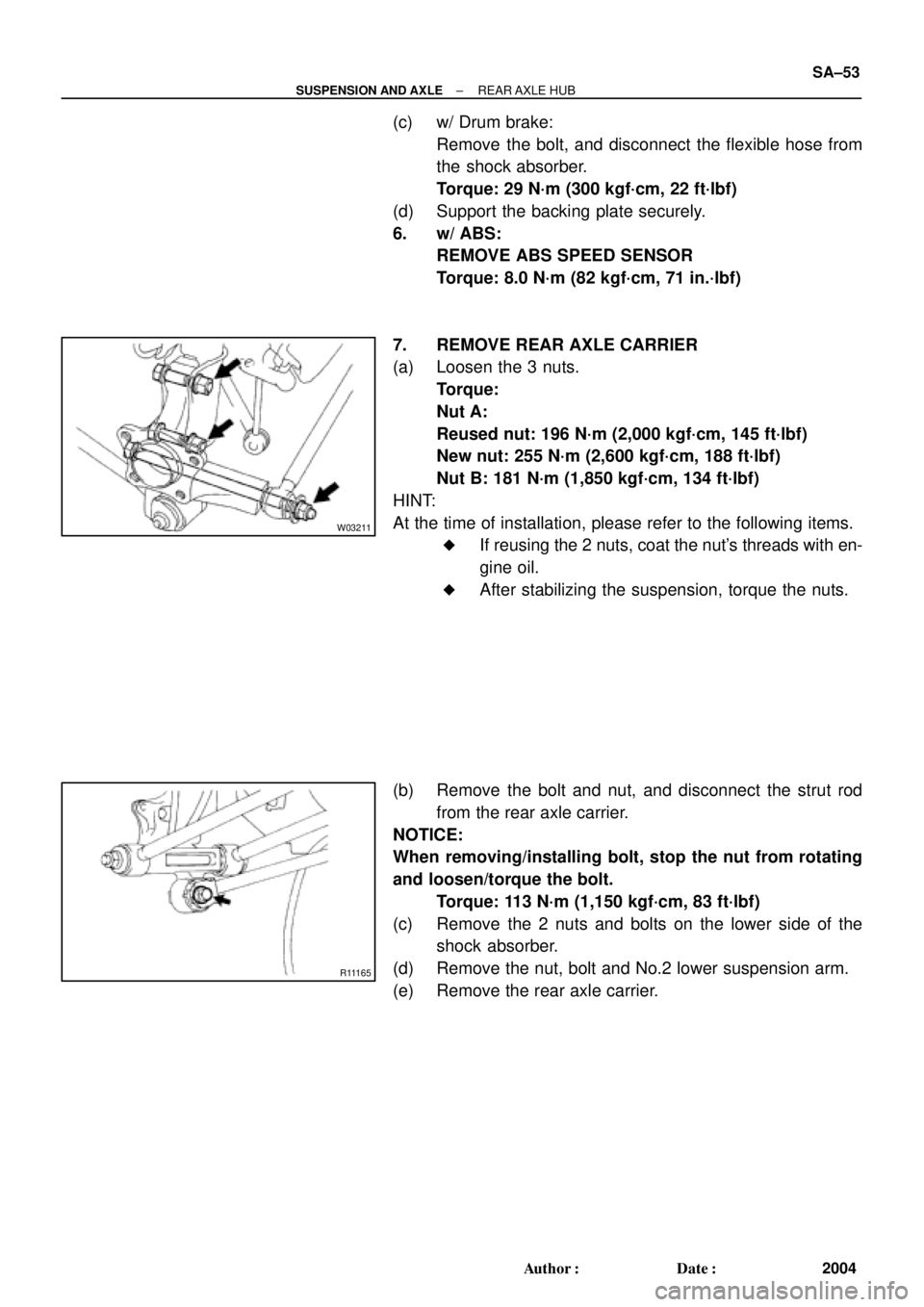
7. REMOVE REAR AXLE CARRIER
(a) Loosen the 3 nuts.
Torque:
Nut A:
Reused nut: 196 N´m (2,000 kgf´cm, 145 ft´lbf)
New nut: 255 N´m (2,600 kgf´cm, 188 ft´lbf)
Nut B: 181 N´m (1,850 kgf´cm, 134 ft´lbf)
HINT:
At the time of installation, please refer to the following items.
�If reusing the 2 nuts, coat the nut's threads with en-
gine oil.
�After stabilizing the suspension, torque the nuts.
(b) Remove the bolt and nut, and disconnect the strut rod
from the rear axle carrier.
NOTICE:
When removing/installing bolt, stop the nut from rotating
and loosen/torque the bolt.
Torque: 113 N´m (1,150 kgf´cm, 83 ft´lbf)
(c) Remove the 2 nuts and bolts on the lower side of the
shock absorber.
(d) Remove the nut, bolt and No.2 lower suspension arm.
(e) Remove the rear axle carrier.
Page 4396 of 4770
SA089±01
W03212
Spring Bumper
Lower Insulator
N´m (kgf´cm, ft´lbf): Specified torque
� Non±reusable partSuspension
Support
Coil Spring
Stabilizer Bar link
Assembly Shock Absorber Rear Side Seatback
Cap
Shock Absorber
ABS Wire Harness
Flexible Hose
49 (500, 36)
5.5 (56, 49 in.´lbf)
39 (400, 29)
29 (300, 22)
39 (400, 29)
Reused nut : 196 (2,000, 145)
New nut : 255 (2,600, 188)
18 (185, 13) SA±56
± SUSPENSION AND AXLEREAR SHOCK ABSORBER
2007 Author�: Date�:
REAR SHOCK ABSORBER
COMPONENTS
Page 4397 of 4770

SA08A±01
R00749
R10288
W03213
± SUSPENSION AND AXLEREAR SHOCK ABSORBER
SA±57
2008 Author�: Date�:
REMOVAL
1. REMOVE REAR SIDE SEATBACK
(See page BO±113 or BO±118)
2. REMOVE REAR WHEEL
Torque: 103 N´m (1,050 kgf´cm, 76 ft´lbf)
3. REMOVE FLEXIBLE HOSE AND ABS SPEED SEN-
SOR WIRE HARNESS (w/ ABS) FROM SHOCK AB-
SORBER
Remove the 2 bolts, flexible hose bracket and ABS wire har-
ness clamp.
Torque:
Flexible hose: 29 N´m (300 kgf´cm, 22 ft´lbf)
ABS wire: 5.5 N´m (56 kgf´cm, 49 in.´lbf)
4. DISCONNECT STABILIZER BAR LINK FROM SHOCK
ABSORBER (See page SA±70)
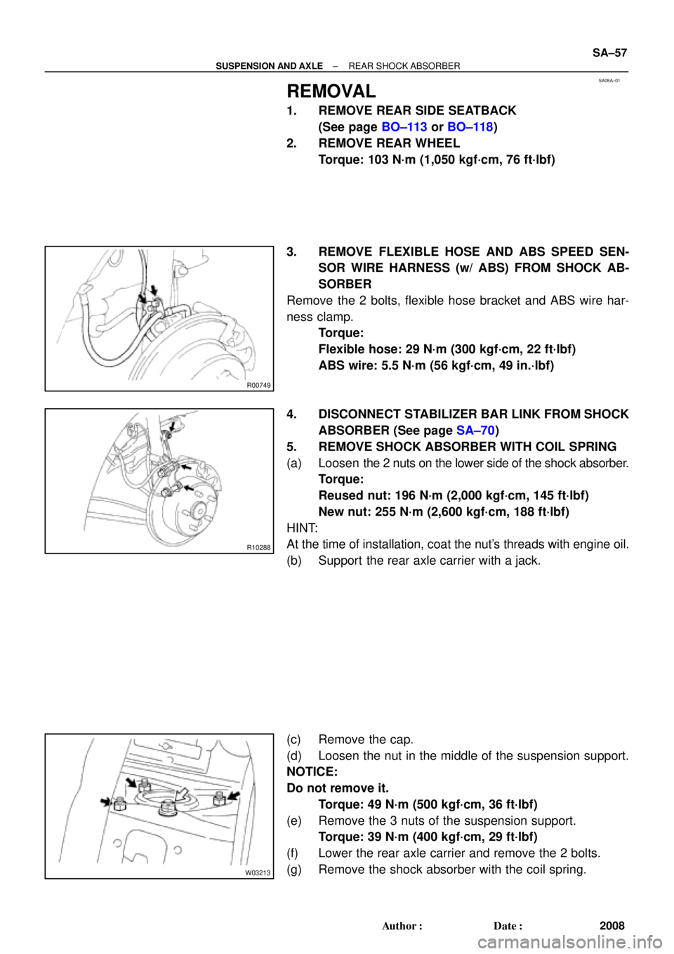
5. REMOVE SHOCK ABSORBER WITH COIL SPRING
(a) Loosen the 2 nuts on the lower side of the shock absorber.
Torque:
Reused nut: 196 N´m (2,000 kgf´cm, 145 ft´lbf)
New nut: 255 N´m (2,600 kgf´cm, 188 ft´lbf)
HINT:
At the time of installation, coat the nut's threads with engine oil.
(b) Support the rear axle carrier with a jack.
(c) Remove the cap.
(d) Loosen the nut in the middle of the suspension support.
NOTICE:
Do not remove it.
Torque: 49 N´m (500 kgf´cm, 36 ft´lbf)
(e) Remove the 3 nuts of the suspension support.
Torque: 39 N´m (400 kgf´cm, 29 ft´lbf)
(f) Lower the rear axle carrier and remove the 2 bolts.
(g) Remove the shock absorber with the coil spring.
Page 4398 of 4770
SA08B±01
W03214
SST SA±58
± SUSPENSION AND AXLEREAR SHOCK ABSORBER
2009 Author�: Date�:
DISASSEMBLY
REMOVE COIL SPRING
(a) Install 2 nuts and a bolt to the bracket at the lower part of
the shock absorber and secure it in a vise.
(b) Using SST, compress the coil spring.
NOTICE:
Do not use an impact wrench. It will damage the SST.
SST 09727±30021
(c) Remove the suspension support nut.
(d) Remove these parts from the shock absorber:
�Suspension support
�Coil spring
�Lower insulator
�Spring bumper
Page 4401 of 4770
SA08E±01
R00911
SST
R00912
R00823
Outside I
± SUSPENSION AND AXLEREAR SHOCK ABSORBER
SA±61
2012 Author�: Date�:
REASSEMBLY
1. INSTALL LOWER INSULATOR
2. INSTALL SPRING BUMPER TO PISTON ROD
3. INSTALL COIL SPRING
(a) Using SST, compress the coil spring.
SST 09727±30021
NOTICE:
Do not use an impact wrench. It will damage the SST.
(b) Install the coil spring to the shock absorber.
HINT:
Fit the lower end of the coil spring into the gap of the spring low-
er seat.
4. INSTALL SUSPENSION SUPPORT
(a) Install the suspension support to the piston rod and tem-
porarily tighten a new nut.
(b) Rotate the suspension support and set it in the direction
shown in the illustration.
(c) Remove the SST.
SST 09727±30021
HINT:
After removing SST, again check the direction of the suspen-
sion support.
Page 4414 of 4770

W03303
Matchmarks SR±12
± STEERINGTILT STEERING COLUMN
2097 Author�: Date�:
2001 CAMRY (RM819U)
3. REMOVE UPPER AND LOWER COLUMN COVERS
(a) Remove the lower No.2 cover from the lower cover.
(b) Remove the 3 screws, upper and lower column covers.
4. REMOVE FRONT DOOR INSIDE SCUFF PLATE
5. REMOVE COWL SIDE TRIM
Remove the clip and cowl side trim.
6. REMOVE No.1 LOWER INSTRUMENT PANEL
(a) Remove the 2 screws.
(b) Disconnect the hood lock control cable.
(c) Remove the No.1 lower instrument panel.
7. REMOVE LH LOWER INSTRUMENT PANEL
Remove the 4 bolts and LH lower instrument panel.
8. REMOVE LOWER INSTRUMENT FINISH PANEL
9. REMOVE COMBINATION SWITCH WITH SPIRAL
CABLE
(a) Disconnect the 3 connectors.
(b) Disconnect the airbag connector.
(c) Remove the 3 screws and combination switch with spiral
cable.
10. REMOVE SPIRAL CABLE (See page BE±23)
NOTICE:
Do not disassemble the cable or apply oil to it.
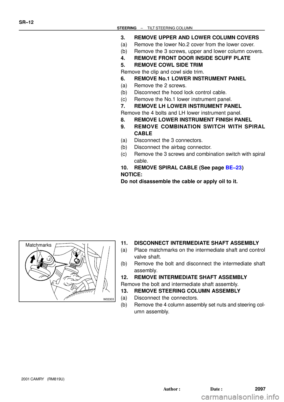
11. DISCONNECT INTERMEDIATE SHAFT ASSEMBLY
(a) Place matchmarks on the intermediate shaft and control
valve shaft.
(b) Remove the bolt and disconnect the intermediate shaft
assembly.
12. REMOVE INTERMEDIATE SHAFT ASSEMBLY
Remove the bolt and intermediate shaft assembly.
13. REMOVE STEERING COLUMN ASSEMBLY
(a) Disconnect the connectors.
(b) Remove the 4 column assembly set nuts and steering col-
umn assembly.