Page 4302 of 4770
 Remove the lower No.2 cover from the lower cover.
(b) Remove the 3 screws.
4.")
W03303
Matchmarks SR±12
± STEERINGTILT STEERING COLUMN
2107 Author�: Date�:
3. REMOVE UPPER AND LOWER COLUMN COVERS
(a) Remove the lower No.2 cover from the lower cover.
(b) Remove the 3 screws.
4. REMOVE FRONT DOOR INSIDE SCUFF PLATE
5. REMOVE COWL SIDE TRIM
Remove the clip.
6. REMOVE No.1 LOWER INSTRUMENT PANEL
(a) Remove the 2 screws.
(b) Disconnect the hood lock control cable.
7. REMOVE LH LOWER INSTRUMENT PANEL
Remove the 4 bolts.
8. REMOVE LOWER INSTRUMENT FINISH PANEL
9. REMOVE COMBINATION SWITCH WITH SPIRAL
CABLE
(a) Disconnect the 3 connectors.
(b) Disconnect the airbag connector.
(c) Remove the 3 screws.
10. REMOVE SPIRAL CABLE
(See page BE±23)
NOTICE:
Do not disassemble the cable or apply oil to it.
11. DISCONNECT INTERMEDIATE SHAFT ASSEMBLY
(a) Place matchmarks on the intermediate shaft and control
valve shaft.
(b) Remove the bolt.
12. REMOVE INTERMEDIATE SHAFT ASSEMBLY
Remove the bolt.
13. REMOVE STEERING COLUMN ASSEMBLY
(a) Disconnect the connectors.
(b) Remove the 4 column assembly set nuts.
Page 4303 of 4770

SR06J±01
W03333
Screw Extractor
W03334
± STEERINGTILT STEERING COLUMN
SR±13
2108 Author�: Date�:
DISASSEMBLY
NOTICE:
When using a vise, do not overtighten it.
1. w/ ENGINE IMMOBILISER SYSTEM:
REMOVE TRANSPONDER KEY COIL WITH KEY CYL-
INDER LAMP ASSEMBLY
Remove the screw.
2. w/ ENGINE IMMOBILISER SYSTEM:
REMOVE KEY CYLINDER LAMP ASSEMBLY
Remove the lamp assembly from the key coil.
3. w/o ENGINE IMMOBILISER SYSTEM:
REMOVE KEY CYLINDER LAMP ASSEMBLY
Remove the screw.
4. REMOVE COLUMN UPPER BRACKET AND COLUMN
UPPER CLAMP
(a) Using a centering punch, mark the center of the 2 ta-
pered±head bolts.
(b) Using a 3±4 mm (0.12±0.16 in.) drill, drill into the 2 bolts.
(c) Using a screw extractor, remove the 2 bolts.
5. REMOVE TURN SIGNAL BRACKET
Remove the 2 bolts.
6. REMOVE TILT LEVER RETURN SPRING
7. REMOVE COLUMN TUBE SUPPORT
(a) Remove the bolt and washer.
(b) Remove the tube support with lower column tube attach-
ment.
(c) Remove the tube attachment from the tube support.
8. REMOVE 2 ENERGY ABSORBING PLATES
(a) Using pliers, remove the energy absorbing clip.
(b) Remove the energy absorbing plate, energy absorbing
plate guide.
Page 4304 of 4770

SR06K±01
W03335
Ignition Key
W03336
SR±14
± STEERINGTILT STEERING COLUMN
2109 Author�: Date�:
INSPECTION
1. INSPECT STEERING LOCK OPERATION
Check that the steering lock mechanism operates properly.
2. IF NECESSARY, REPLACE KEY CYLINDER
(a) Place the ignition key at the ACC position.
(b) Push down the stop pin with a screwdriver, and pull out
the cylinder.
(c) Install a new cylinder.
HINT:
Make sure the key is at the ACC position.
3. INSPECT IGNITION SWITCH
(See page BE±14)
4. IF NECESSARY, REPLACE IGNITION SWITCH
(a) Remove the 2 screws.
(b) Install a new switch with the 2 screws.
5. INSPECT KEY UNLOCK WARNING SWITCH
(See page BE±14)
6. IF NECESSARY, REPLACE KEY UNLOCK WARNING
SWITCH
(a) Slide out the switch.
(b) Install a new switch.
7. A/T:
INSPECT KEY INTERLOCK SOLENOID
(A140E: See page AX±13)
(A541E: See page AX±17)
8. A/T:
IF NECESSARY, REPLACE KEY INTERLOCK SOLE-
NOID
(a) Remove the 2 screws.
(b) Install a new solenoid with the 2 screws.
9. w/ ENGINE IMMOBILISER SYSTEM:
INSPECT TRANSPONDER KEY COIL
(See page BE±128)
10. w/ ENGINE IMMOBILISER SYSTEM:
IF NECESSARY, REPLACE TRANSPONDER KEY
COIL
11. w/ ENGINE IMMOBILISER SYSTEM:
IF NECESSARY, REPLACE TRANSPONDER KEY AM-
PLIFIER
(a) Remove the 2 screws.
(b) Install a new key amplifier with the 2 screws.
Page 4305 of 4770
 Install the en")
SR06L±01
W03347
W03337
± STEERINGTILT STEERING COLUMN
SR±15
2110 Author�: Date�:
REASSEMBLY
NOTICE:
When using a vise, do not overtighten it.
1. INSTALL 2 ENERGY ABSORBING PLATES
(a) Install the energy absorbing plate guide and absorbing
plate.
(b) Install the new energy absorbing clip.
2. INSTALL COLUMN TUBE SUPPORT
(a) Install the tube attachment to the tube support.
(b) Torque the bolt and washer.
Torque: 19 N´m (195 kgf´cm, 14 ft´lbf)
3. INSTALL TILT LEVER RETURN SPRING
4. INSTALL TURN SIGNAL BRACKET
Torque the 2 bolts.
Torque: 7 N´m (70 kgf´cm, 61 in.´lbf)
5. INSTALL COLUMN UPPER BRACKET AND COLUMN
UPPER CLAMP
Tighten the 2 new tapered±head bolts until the bolt heads break
off.
6. w/ ENGINE EMMOBILISER SYSTEM:
INSTALL KEY CYLINDER LAMP ASSEMBLY
Install the lamp assembly to the key coil.
7. w/ ENGINE EMMOBILISER SYSTEM:
INSTALL TRANSPONDER KEY COIL WITH KEY CYL-
INDER LAMP ASSEMBLY
Tighten the screw.
8. w/o ENGINE EMMOBILISER SYSTEM:
INSTALL KEY CYLINDER LAMP ASSEMBLY
Tighten the screw.
Page 4308 of 4770
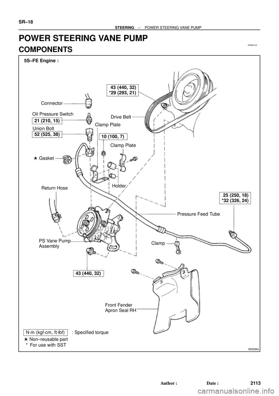
SR06N±03
W03364
Pressure Feed Tube Connector
Oil Pressure Switch
Drive Belt
Clamp Plate
Clamp Plate
Holder
Clamp
Front Fender
Apron Seal RH PS Vane Pump
AssemblyReturn Hose � Gasket Union Bolt 5S±FE Engine :
21 (210, 15)
43 (440, 32)
*29 (293, 21)
10 (100, 7)
25 (250, 18)
*32 (326, 24)
43 (440, 32)
52 (525, 38)
N´m (kgf´cm, ft´lbf) : Specified torque
� Non±reusable part
For use with SST * SR±18
± STEERINGPOWER STEERING VANE PUMP
2113 Author�: Date�:
POWER STEERING VANE PUMP
COMPONENTS
Page 4309 of 4770
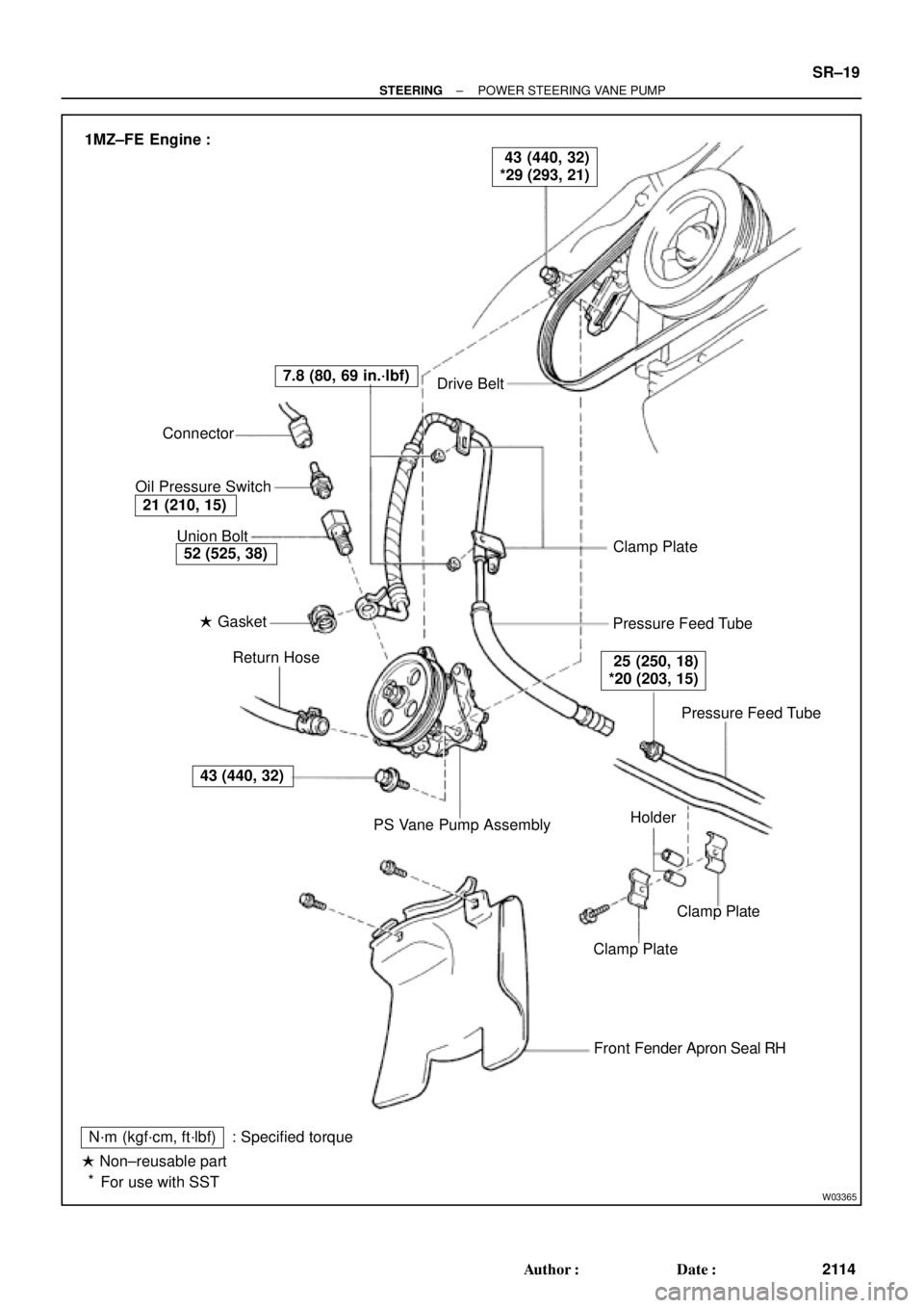
W03365
Drive Belt
Clamp Plate
Pressure Feed Tube
Pressure Feed Tube
Clamp Plate
Clamp Plate
Front Fender Apron Seal RH
N´m (kgf´cm, ft´lbf)
� Non±reusable part
For use with SST: Specified torquePS Vane Pump Assembly Return Hose � Gasket Union Bolt Connector
Oil Pressure Switch
43 (440, 32)
52 (525, 38)
21 (210, 15)
7.8 (80, 69 in.´lbf)
25 (250, 18)
*20 (203, 15)
43 (440, 32)
*29 (293, 21) 1MZ±FE Engine :
Holder
*
± STEERINGPOWER STEERING VANE PUMP
SR±19
2114 Author�: Date�:
Page 4310 of 4770
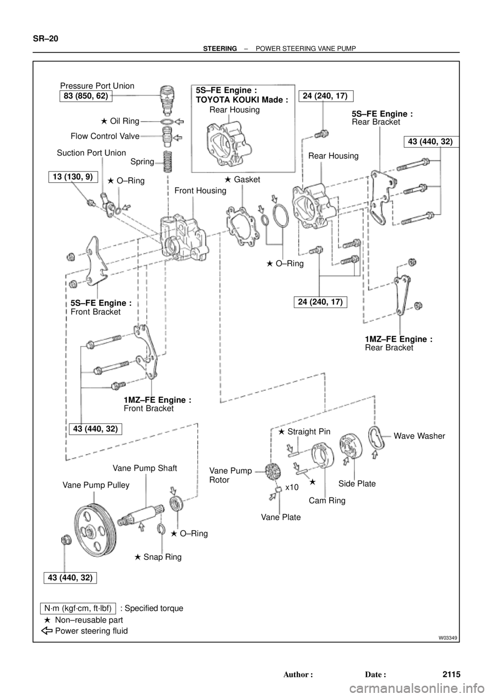
W03349
Pressure Port Union
� Oil Ring
Flow Control Valve
Suction Port Union
Spring
� O±Ring
Front Housing� Gasket Rear Housing
Rear Bracket
Rear Housing
� O±Ring
Rear Bracket
Wave Washer
�
Cam Ring � Straight Pin
Vane Plate Rotor
Side Plate Vane Pump
x10
� O±Ring
� Snap Ring
N´m (kgf´cm, ft´lbf)
Non±reusable part
Power steering fluid: Specified torque Vane Pump Shaft
Vane Pump PulleyFront Bracket Front Bracket
�
5S±FE Engine :
TOYOTA KOUKI Made :24 (240, 17)
43 (440, 32)
24 (240, 17)
83 (850, 62)
13 (130, 9)
5S±FE Engine :5S±FE Engine :
1MZ±FE Engine :1MZ±FE Engine :
43 (440, 32)
43 (440, 32) SR±20
± STEERINGPOWER STEERING VANE PUMP
2115 Author�: Date�:
Page 4311 of 4770

SR06O±01
W04220
5S±FE Engine :
1MZ±FE Engine :
Pressure
Feed TubeSST SST
W03360
Example 5S±FE Engine :
A
B
± STEERINGPOWER STEERING VANE PUMP
SR±21
2116 Author�: Date�:
REMOVAL
1. REMOVE FRONT FENDER APRON SEAL RH
Remove the 2 bolts.
2. DISCONNECT RETURN HOSE
NOTICE:
Take care not to spill fluid on the drive belt.
3. DISCONNECT PRESSURE FEED TUBE
(a) 5S±FE Engine:
Remove the clamp plate set bolt and nut.
(b) 5S±FE Engine:
Remove the 2 clamp plates and 2 holders from the tube.
(c) 5S±FE Engine:
Remove the clamp from the tube.
(d) 1MZ±FE Engine:
Remove the 2 clamp plate set nuts.
(e) 1MZ±FE Engine:
Remove the bolt.
(f) 1MZ±FE Engine:
Remove the 2 clamp plates and 2 holders from the tube.
(g) 5S±FE and 1MZ±FE Engines:
Using SST, disconnect the tube.
SST 09631±22020
4. REMOVE DRIVE BELT
Loosen the 2 (A and B) bolts.
5. REMOVE PS VANE PUMP ASSEMBLY WITH PRES-
SURE FEED TUBE
(a) Disconnect the connector from the oil pressure switch.
(b) Loosen bolt A sufficiently so that pump assembly can be
removed.
HINT:
Bolt A cannot be removed.
6. REMOVE PRESSURE FEED TUBE
(a) Remove the oil pressure switch from the union bolt.
NOTICE:
Be careful not to drop the switch.
If the switch is dropped or strongly damaged, replace it with a
new one.
(b) Remove the union bolt and gasket.