Page 4313 of 4770

SR06Q±01
R15196
Caliper Gauge
Micrometer
Vane Pump Shaft
Bushing
Front Housing
N00372
Thickness
Height
Length
R10282
Feeler Gauge
± STEERINGPOWER STEERING VANE PUMP
SR±23
2118 Author�: Date�:
INSPECTION
NOTICE:
When using a vise, do not overtighten it.
1. CHECK OIL CLEARANCE BETWEEN VANE PUMP
SHAFT AND BUSHING
Using a micrometer and caliper gauge, measure the oil clear-
ance.
5S±FE and 1MZ±FE Engines:
Standard clearance:
0.03 ± 0.05 mm (0.0012 ± 0.0020 in.)
Maximum clearance: 0.07 mm (0.0028 in.)
If it is more than the maximum, replace the front housing and
vane pump shaft.
2. INSPECT VANE PUMP ROTOR AND VANE PLATES
(a) Using a micrometer, measure the height, thickness and
length of the plates.
5S±FE and 1MZ±FE Engines:
Minimum height: 8.6 mm (0.339 in.)
Minimum thickness: 1.397 mm (0.0550 in.)
Minimum length: 14.991 mm (0.5902 In.)
(b) Using a feeler gauge, measure the clearance between
the rotor groove and plate.
5S±FE and 1MZ±FE Engines:
Maximum clearance: 0.035 mm (0.0014 in.)
If it is more than the maximum, replace the plate and/or rotor
with one having the same mark stamped on the cam ring.
Page 4315 of 4770
R08702
Calipers
R11290
Vinyl Tape
W03541
Press
SST
Oil Seal
± STEERINGPOWER STEERING VANE PUMP
SR±25
2120 Author�: Date�:
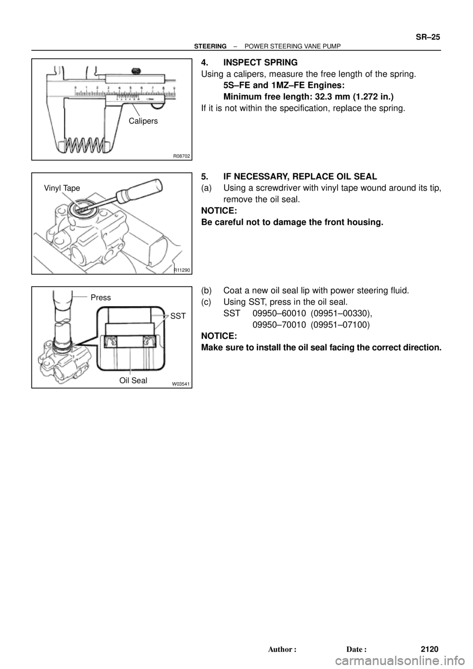
4. INSPECT SPRING
Using a calipers, measure the free length of the spring.
5S±FE and 1MZ±FE Engines:
Minimum free length: 32.3 mm (1.272 in.)
If it is not within the specification, replace the spring.
5. IF NECESSARY, REPLACE OIL SEAL
(a) Using a screwdriver with vinyl tape wound around its tip,
remove the oil seal.
NOTICE:
Be careful not to damage the front housing.
(b) Coat a new oil seal lip with power steering fluid.
(c) Using SST, press in the oil seal.
SST 09950±60010 (09951±00330),
09950±70010 (09951±07100)
NOTICE:
Make sure to install the oil seal facing the correct direction.
Page 4318 of 4770
SR06S±01
W03361
5S±FE Engine :
1MZ±FE Engine :Pressure Feed Tube
Stopper
Pressure
Feed
StopperTube
W03360
Example 5S±FE Engine :
A
B
W03542
5S±FE Engine :
SST
Fulcrum
Length SR±28
± STEERINGPOWER STEERING VANE PUMP
2123 Author�: Date�:
INSTALLATION
1. INSTALL PRESSURE FEED TUBE
(a) Torque the union bolt with a new gasket.
HINT:
Make sure the stopper of the tube is touching the front bracket,
as shown, then torque the union bolt.
5S±FE and 1MZ±FE Engines:
Torque: 52 N´m (525 kgf´cm, 38 ft´lbf)
(b) Install the oil pressure switch to the union bolt.
5S±FE and 1MZ±FE Engines:
Torque: 21 N´m (210 kgf´cm, 15 ft´lbf)
2. INSTALL PS VANE PUMP ASSEMBLY WITH PRESS-
ER FEED TUBE
Temporarily tighten the 2 (A and B) bolts.
3. INSTALL DRIVE BELT
(a) Adjust drive belt tension.
(See page SR±3)
(b) 5S±FE Engine:
Using SST, torque the A bolt.
SST 09249±63010
Torque: 29 N´m (293 kgf´cm, 21 ft´lbf)
HINT:
Use a torque wrench with a fulcrum length of 300 mm (11.81
in.).
Page 4319 of 4770

W03543
1MZ±FE Engine :
Engine Wire Clamp
Fulcrum
Length
SST
W04221
5S±FE Engine :
1MZ±FE Engine :Fulcrum
Length
SST Pressure
Feed Tube
Fulcrum
LengthSST
± STEERINGPOWER STEERING VANE PUMP
SR±29
2124 Author�: Date�:
(c) 1MZ±FE Engine:
Using SST, torque the A bolt.
SST 09249±63010
Torque: 29 N´m (293 kgf´cm, 21 ft´lbf)
HINT:
�Use a torque wrench with a fulcrum length of 300 mm
(11.81 in.).
�Disconnect the clamp with engine wire.
(d) Torque the B bolt.
5S±FE and 1MZ±FE Engines:
Torque: 43 N´m (440 kgf´cm, 32 ft´lbf)
(e) Connect the connector to the oil pressure switch.
NOTICE:
Be careful for oil on the connector.
4. CONNECT PRESSURE FEED TUBE
(a) Using SST, connect the tube.
SST 09631±22020
5S±FE Engine:
Torque: 32 N´m (326 kgf´cm, 24 ft´lbf)
1MZ±FE Engine:
Torque: 20 N´m (203 kgf´cm, 15 ft´lbf)
HINT:
�Use a torque wrench with a fulcrum length of 300 mm
(11.81 in.).
�This torque value is effective in case that SST is parallel
to a torque wrench.
(b) 5S±FE Engine:
Install the clamp to the tube.
(c) 5S±FE Engine:
Install the 2 clamp plates and 2 holders to the tube.
(d) 5S±FE Engine:
Install the clamp plate set bolt.
(e) 5S±FE Engine:
Install the clamp plate set nut.
Torque: 10 N´m (100 kgf´cm, 7 ft´lbf)
(f) 1MZ±FE Engine:
Install the 2 clamp plates and 2 holders to the tube.
(g) 1MZ±FE Engine:
Tighten the bolt.
(h) 1MZ±FE Engine:
Install the 2 clamp plate set nuts.
Torque: 7.8 N´m (80 kgf´cm, 69 in.´lbf)
5. CONNECT RETURN HOSE
Page 4322 of 4770
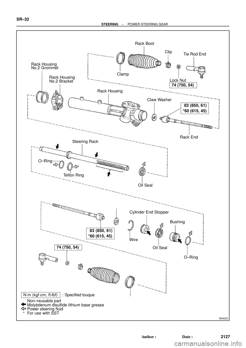
W04225
Rack Housing
No.2 Grommet
Rack Housing
No.2 Bracket
Rack Housing
� Claw Washer
Rack End Lock NutTie Rod End Rack Boot
� ClampClip
Steering Rack
� Teflon Ring
� Oil Seal
Cylinder End Stopper
Bushing
� O±Ring � Oil Seal � Wire �
�
N´m (kgf´cm, ft´lbf) : Specified touque
Power steering fluid
For use with SST Non±reusable part
Molybdenum disulfide lithium base grease �
*
74 (750, 54)
83 (850, 61)
*60 (615, 45)
83 (850, 61)
*60 (615, 45)
74 (750, 54)
� O±Ring SR±32
± STEERINGPOWER STEERING GEAR
2127 Author�: Date�:
Page 4323 of 4770
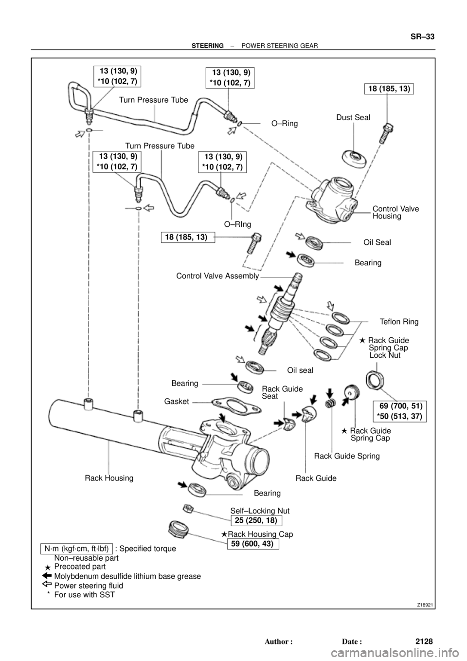
Z18921
Turn Pressure Tube
� O±RingDust Seal
Turn Pressure Tube
� O±RIngControl Valve
Housing
� Oil Seal
� Bearing
� Teflon Ring
� Rack Guide
Spring Cap
Lock Nut
� Rack Guide
Spring Cap
Rack Guide Spring
Rack Guide
� Self±Locking Nut� Bearing
�Rack Housing Cap
N´m (kgf´cm, ft´lbf) : Specified torque
Non±reusable part
Precoated part
Molybdenum desulfide lithium base grease
Power steering fluid
For use with SSTRack Housing� Bearing
� GasketControl Valve Assembly � �
13 (130, 9)
*10 (102, 7) 13 (130, 9)
*10 (102, 7)
18 (185, 13)
69 (700, 51)
*50 (513, 37)
25 (250, 18)
59 (600, 43)
18 (185, 13)
13 (130, 9)
*10 (102, 7) 13 (130, 9)
*10 (102, 7)
�
�
*Rack Guide
Seat� Oil seal
± STEERINGPOWER STEERING GEAR
SR±33
2128 Author�: Date�:
Page 4327 of 4770
 To prevent")
R11554
Vinyl Tape
Shop RagPress
R11649
Matchmarks
R11650
R11651
Cylinder End
StopperWire
SST
± STEERINGPOWER STEERING GEAR
SR±37
2132 Author�: Date�:
12. REMOVE CONTROL VALVE ASSEMBLY
(a) To prevent oil seal lip damage, wind vinyl tape on the ser-
rated part of the valve shaft.
(b) Press out the valve assembly with the oil seal.
NOTICE:
�Place a shop rag between the valve housing and the
blocks.
�Be careful not to drop the valve assembly.
�Be careful not to damage the oil seal lip.
13. REMOVE OIL SEAL
Remove the oil seal from the control valve assembly.
14. REMOVE RACK HOUSING NO.2 BRACKET AND
GROMMET
(a) Place matchmarks on the bracket and rack housing.
(b) Using a screwdriver, pry the clamp of the bracket.
(c) Remove the grommet from the bracket.
15. REMOVE CYLINDER END STOPPER
(a) Using SST, turn the stopper clockwise until the wire end
is visible through the service hole.
SST 09631±10021
(b) Using SST, turn the stopper counterclockwise, and re-
move the wire.
SST 09631±10021
Page 4328 of 4770
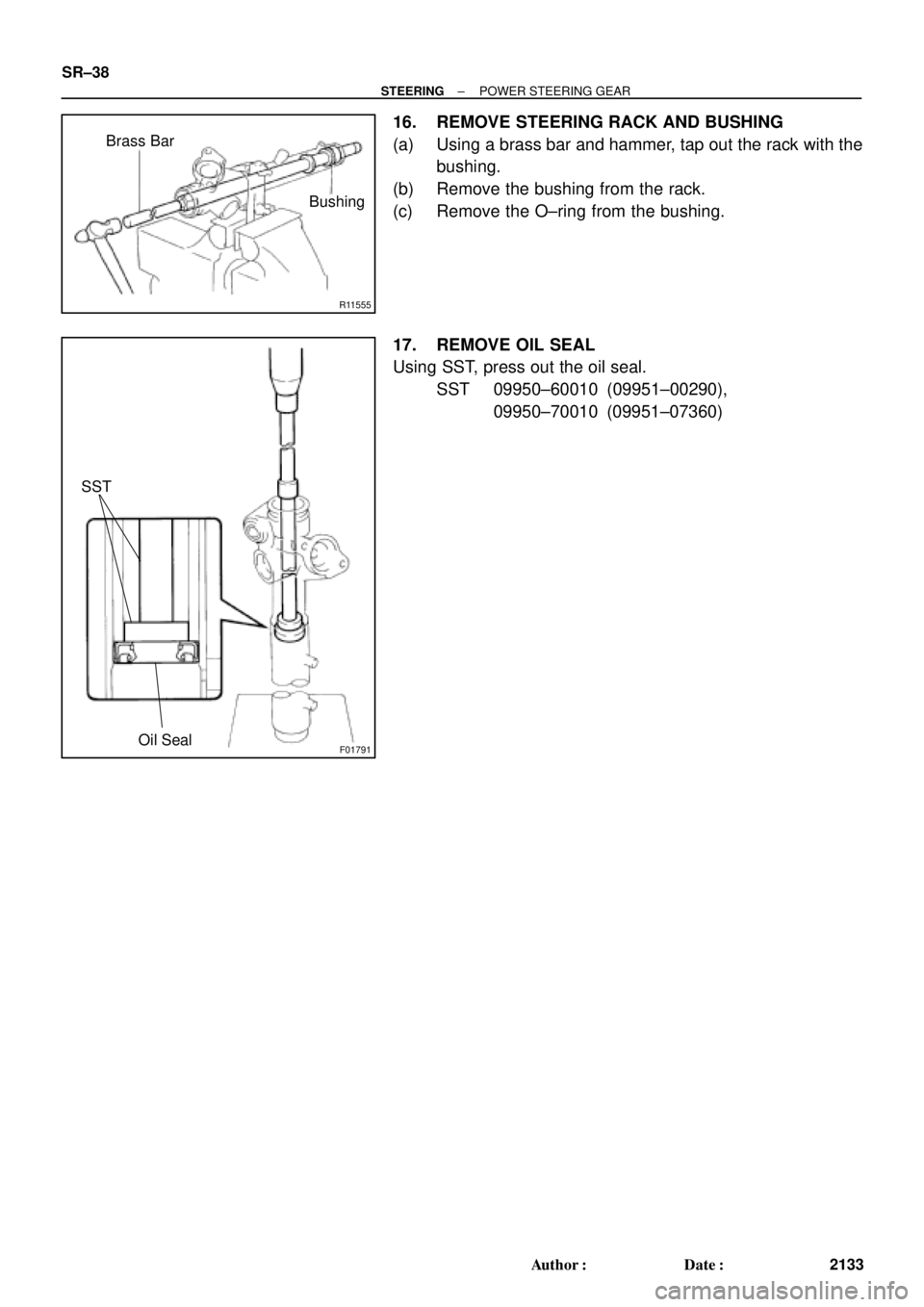
R11555
Brass Bar
Bushing
F01791
SST
Oil Seal
SR±38
± STEERINGPOWER STEERING GEAR
2133 Author�: Date�:
16. REMOVE STEERING RACK AND BUSHING
(a) Using a brass bar and hammer, tap out the rack with the
bushing.
(b) Remove the bushing from the rack.
(c) Remove the O±ring from the bushing.
17. REMOVE OIL SEAL
Using SST, press out the oil seal.
SST 09950±60010 (09951±00290),
09950±70010 (09951±07360)