Page 4278 of 4770
ST01X±03
P10584
Ohmmeter
Continuity
P10585
Ohmmeter
No Continuity
P10586
P10587
ST0040
ST±8
± STARTING (1MZ±FE)STARTER
1735 Author�: Date�:
INSPECTION
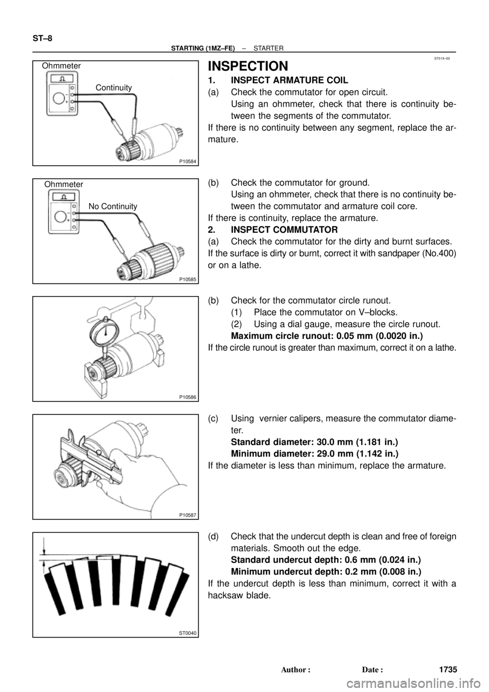
1. INSPECT ARMATURE COIL
(a) Check the commutator for open circuit.
Using an ohmmeter, check that there is continuity be-
tween the segments of the commutator.
If there is no continuity between any segment, replace the ar-
mature.
(b) Check the commutator for ground.
Using an ohmmeter, check that there is no continuity be-
tween the commutator and armature coil core.
If there is continuity, replace the armature.
2. INSPECT COMMUTATOR
(a) Check the commutator for the dirty and burnt surfaces.
If the surface is dirty or burnt, correct it with sandpaper (No.400)
or on a lathe.
(b) Check for the commutator circle runout.
(1) Place the commutator on V±blocks.
(2) Using a dial gauge, measure the circle runout.
Maximum circle runout: 0.05 mm (0.0020 in.)
If the circle runout is greater than maximum, correct it on a lathe.
(c) Using vernier calipers, measure the commutator diame-
ter.
Standard diameter: 30.0 mm (1.181 in.)
Minimum diameter: 29.0 mm (1.142 in.)
If the diameter is less than minimum, replace the armature.
(d) Check that the undercut depth is clean and free of foreign
materials. Smooth out the edge.
Standard undercut depth: 0.6 mm (0.024 in.)
Minimum undercut depth: 0.2 mm (0.008 in.)
If the undercut depth is less than minimum, correct it with a
hacksaw blade.
Page 4279 of 4770
P10588
Ohmmeter
Continuity
P10589
Ohmmeter
No Continuity
Z10079
Brush Holder Side
Field Flame SideLength
Length
ST0019
± STARTING (1MZ±FE)STARTER
ST±9
1736 Author�: Date�:
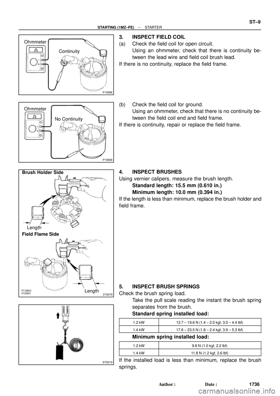
3. INSPECT FIELD COIL
(a) Check the field coil for open circuit.
Using an ohmmeter, check that there is continuity be-
tween the lead wire and field coil brush lead.
If there is no continuity, replace the field frame.
(b) Check the field coil for ground.
Using an ohmmeter, check that there is no continuity be-
tween the field coil end and field frame.
If there is continuity, repair or replace the field frame.
4. INSPECT BRUSHES
Using vernier calipers, measure the brush length.
Standard length: 15.5 mm (0.610 in.)
Minimum length: 10.0 mm (0.394 in.)
If the length is less than minimum, replace the brush holder and
field frame.
5. INSPECT BRUSH SPRINGS
Check the brush spring load.
Take the pull scale reading the instant the brush spring
separates from the brush.
Standard spring installed load:
1.2 kW13.7 ± 19.6 N (1.4 ± 2.0 kgf, 3.0 ± 4.4 lbf)
1.4 kW17.6 ± 23.5 N (1.8 ± 2.4 kgf, 3.9 ± 5.3 lbf)
Minimum spring installed load:
1.2 kW9.8 N (1.0 kgf, 2.2 lbf)
1.4 kW11.8 N (1.2 kgf, 2.6 lbf)
If the installed load is less than minimum, replace the brush
springs.
Page 4280 of 4770
P13481
No Continuity Ohmmeter
B01162
Lock
Free
B01163
Ohmmeter
Terminal 50Terminal C
Continuity
B01164
Ohmmeter
Terminal 50Continuity
ST±10
± STARTING (1MZ±FE)STARTER
1737 Author�: Date�:
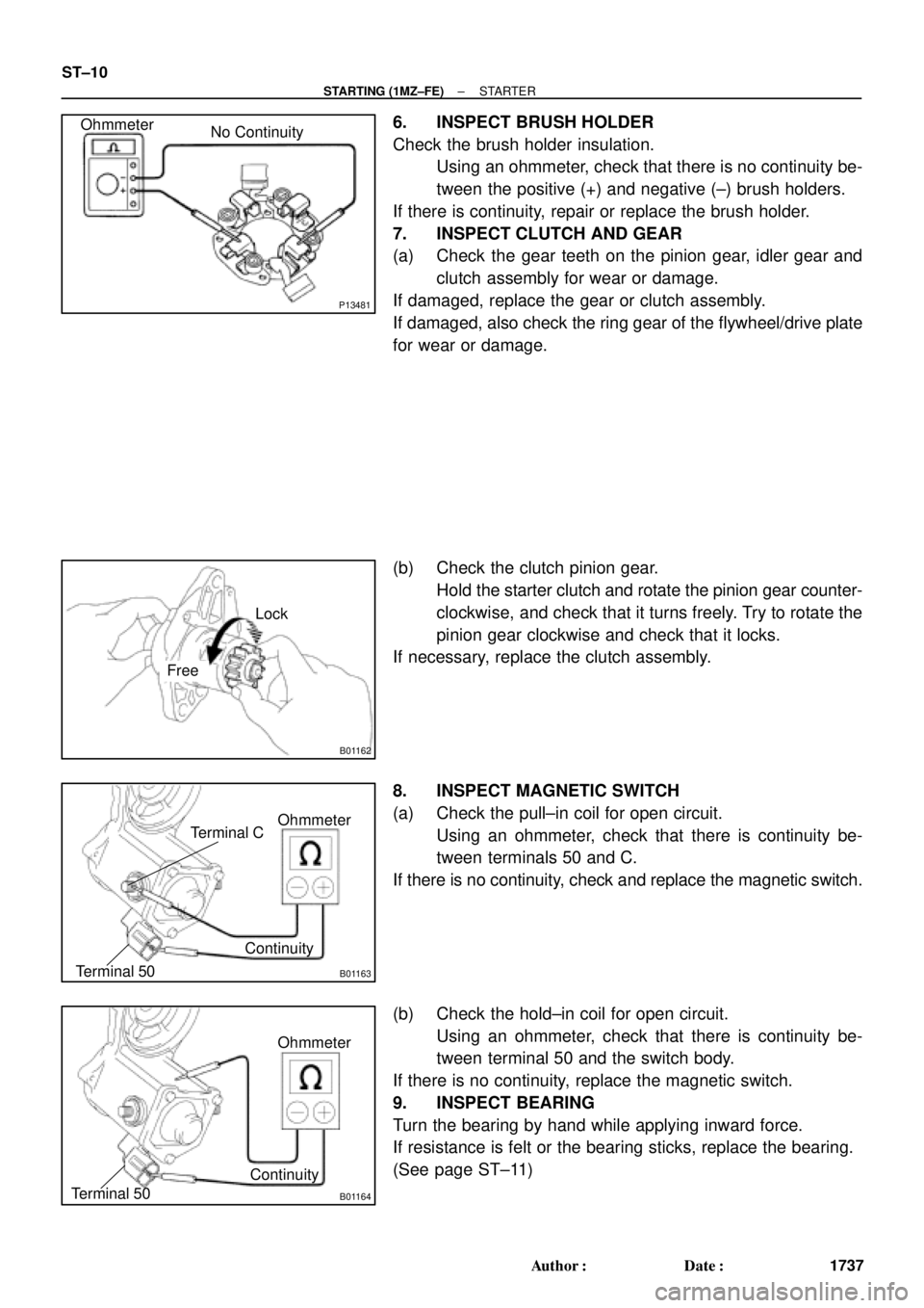
6. INSPECT BRUSH HOLDER
Check the brush holder insulation.
Using an ohmmeter, check that there is no continuity be-
tween the positive (+) and negative (±) brush holders.
If there is continuity, repair or replace the brush holder.
7. INSPECT CLUTCH AND GEAR
(a) Check the gear teeth on the pinion gear, idler gear and
clutch assembly for wear or damage.
If damaged, replace the gear or clutch assembly.
If damaged, also check the ring gear of the flywheel/drive plate
for wear or damage.
(b) Check the clutch pinion gear.
Hold the starter clutch and rotate the pinion gear counter-
clockwise, and check that it turns freely. Try to rotate the
pinion gear clockwise and check that it locks.
If necessary, replace the clutch assembly.
8. INSPECT MAGNETIC SWITCH
(a) Check the pull±in coil for open circuit.
Using an ohmmeter, check that there is continuity be-
tween terminals 50 and C.
If there is no continuity, check and replace the magnetic switch.
(b) Check the hold±in coil for open circuit.
Using an ohmmeter, check that there is continuity be-
tween terminal 50 and the switch body.
If there is no continuity, replace the magnetic switch.
9. INSPECT BEARING
Turn the bearing by hand while applying inward force.
If resistance is felt or the bearing sticks, replace the bearing.
(See page ST±11)
Page 4286 of 4770
B01240
SST
B01241
ST±16
± STARTING (1MZ±FE)STARTER
1743 Author�: Date�: �
If the contact plate is not pressed down with the spe-
cified pressure, the contact plate may tilt due to coil
deformation or the tightening of the nut.
(2) Using SST, tighten the nuts to the specified torque.
SST 09810±38140
Torque: 17 N´m (173 kgf´cm, 13 ft´lbf)
NOTICE:
If the nut is over tightened, it may cause cracks on the in-
side of the insulator.
(h) Clean the contact surfaces of the remaining contact plate
and plunger with a dry shop rag.
(i) Reinstall the plunger, new gasket and end cover with the
3 bolts.
Torque: 2.5 N´m (26 kgf´cm, 23 in.´lbf)
Page 4288 of 4770
ST020±01
B01242Terminal 50Terminal C
Battery
B01243
Terminal C
Battery
Disconnect
B01244
Disconnect
Battery
B01245Terminal 50
Terminal 30
Battery
Ammeter
ST±18
± STARTING (1MZ±FE)STARTER
1745 Author�: Date�:
TEST
NOTICE:
These tests must be done within 3 to 5 seconds to avoid
burning out the coil.
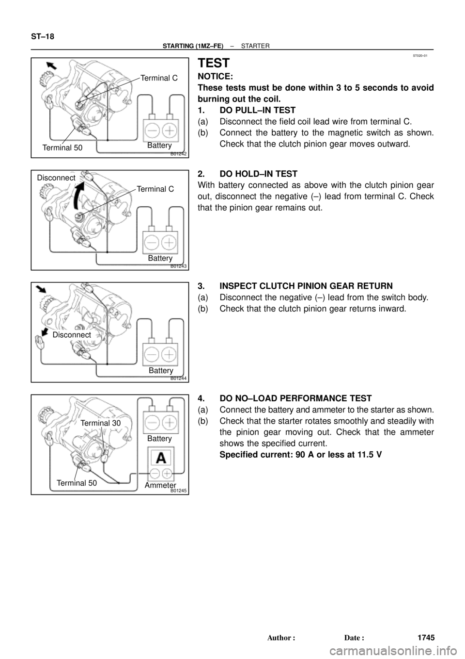
1. DO PULL±IN TEST
(a) Disconnect the field coil lead wire from terminal C.
(b) Connect the battery to the magnetic switch as shown.
Check that the clutch pinion gear moves outward.
2. DO HOLD±IN TEST
With battery connected as above with the clutch pinion gear
out, disconnect the negative (±) lead from terminal C. Check
that the pinion gear remains out.
3. INSPECT CLUTCH PINION GEAR RETURN
(a) Disconnect the negative (±) lead from the switch body.
(b) Check that the clutch pinion gear returns inward.
4. DO NO±LOAD PERFORMANCE TEST
(a) Connect the battery and ammeter to the starter as shown.
(b) Check that the starter rotates smoothly and steadily with
the pinion gear moving out. Check that the ammeter
shows the specified current.
Specified current: 90 A or less at 11.5 V
Page 4295 of 4770
SR06F±01
R00427
R09599
Normal Abnormal
R11562
5 mm (0.2 in.)
or less
Engine Idling Engine Stopped
± STEERINGPOWER STEERING FLUID
SR±5
2100 Author�: Date�:
INSPECTION
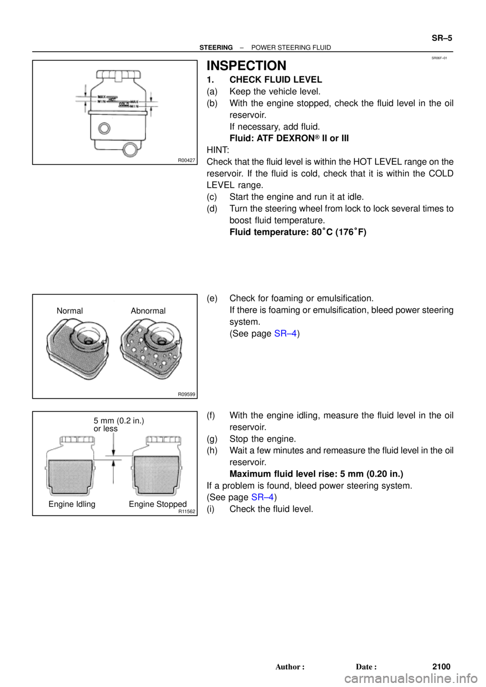
1. CHECK FLUID LEVEL
(a) Keep the vehicle level.
(b) With the engine stopped, check the fluid level in the oil
reservoir.
If necessary, add fluid.
Fluid: ATF DEXRON® II or III
HINT:
Check that the fluid level is within the HOT LEVEL range on the
reservoir. If the fluid is cold, check that it is within the COLD
LEVEL range.
(c) Start the engine and run it at idle.
(d) Turn the steering wheel from lock to lock several times to
boost fluid temperature.
Fluid temperature: 80°C (176°F)
(e) Check for foaming or emulsification.
If there is foaming or emulsification, bleed power steering
system.
(See page SR±4)
(f) With the engine idling, measure the fluid level in the oil
reservoir.
(g) Stop the engine.
(h) Wait a few minutes and remeasure the fluid level in the oil
reservoir.
Maximum fluid level rise: 5 mm (0.20 in.)
If a problem is found, bleed power steering system.
(See page SR±4)
(i) Check the fluid level.
Page 4297 of 4770
Z15498
Oil
PS Gear
Closed
SSTPS Vane
Pump Reservoir
Z15499
Oil
PS Gear
SSTPS Vane
Pump Reservoir
Open
Z15500
Oil
PS Gear
SSTPS Vane
Pump Reservoir
Lock Position
± STEERINGPOWER STEERING FLUID
SR±7
2102 Author�: Date�:
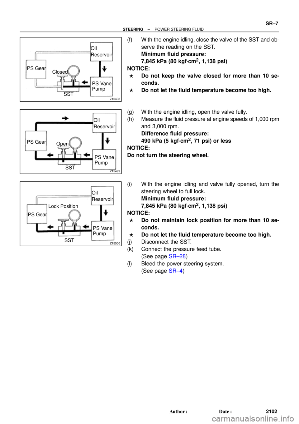
(f) With the engine idling, close the valve of the SST and ob-
serve the reading on the SST.
Minimum fluid pressure:
7,845 kPa (80 kgf´cm
2, 1,138 psi)
NOTICE:
�Do not keep the valve closed for more than 10 se-
conds.
�Do not let the fluid temperature become too high.
(g) With the engine idling, open the valve fully.
(h) Measure the fluid pressure at engine speeds of 1,000 rpm
and 3,000 rpm.
Difference fluid pressure:
490 kPa (5 kgf´cm
2, 71 psi) or less
NOTICE:
Do not turn the steering wheel.
(i) With the engine idling and valve fully opened, turn the
steering wheel to full lock.
Minimum fluid pressure:
7,845 kPa (80 kgf´cm
2, 1,138 psi)
NOTICE:
�Do not maintain lock position for more than 10 se-
conds.
�Do not let the fluid temperature become too high.
(j) Disconnect the SST.
(k) Connect the pressure feed tube.
(See page SR±28)
(l) Bleed the power steering system.
(See page SR±4)
Page 4300 of 4770
F01476
Key Unlock Warning Switch
Column Upper Bracket Ignition Switch
Energy Absorbing PlateTransponder Key Coil Key Cylinder Lamp Assembly
Key
Interlock
Solenoid Key Cylinder
Transponder Key
Amplifier
Energy Absorbing Plate
Guide� Energy Absorbing Clip
Energy Absorbing Plate
Energy Absorbing Plate
Guide
� Energy Absorbing Clip Column TubeTilt Lever
Return Spring
� Tapered±Head Bolt Column Upper Tube Turn Signal Bracket
Lower Column Tube AttachmentColumn Tube Support
7 (70, 61 in.´lbf)
19 (195, 14)
N´m (kgf´cm, ft´lbf): Specified torque
� Non±reusable partw/ ENGINE IMMOBILISER SYSTEM:
A/T: SR±10
± STEERINGTILT STEERING COLUMN
2105 Author�: Date�: