Page 4329 of 4770

SR06W±01
R10072
Dial Indicator
F01792
Press
SST
Oil Seal
Bearing
W03560
Press
SST
SST Bearing
F01793
Press
SST
Bearing
F01794
Brass Bar
Bearing
± STEERINGPOWER STEERING GEAR
SR±39
2134 Author�: Date�:
INSPECTION
NOTICE:
When using a vise, do not overtighten it.
1. INSPECT STEERING RACK
(a) Using a dial indicator, check the rack for runout and for
teeth wear and damage.
Maximum runout: 0.03 mm (0.0118 in.)
(b) Check the back surface for wear and damage.
2. IF NECESSARY, REPLACE OIL SEAL AND BEARING
(a) Using SST, press out the oil seal and bearing from the
control valve housing.
SST 09950±60010 (09951±00250),
09950±70010 (09951±07200)
(b) Coat a new oil seal lip with power steering fluid.
(c) Using SST, press in the oil seal.
SST 09950±60010 (09951±00180, 09951±00320,
09952±06010), 09950±70010 (09951±07200)
NOTICE:
Make sure to install the oil seal facing the correct direction.
(d) Coat a new bearing with molybdenum disulfide lithium
base grease.
(e) Using SST, press in the bearing.
SST 09950±60010 (09951±00340),
09950±70010 (09951±07200)
3. IF NECESSARY, REPLACE 2 BEARINGS
(a) Using a brass bar and hammer, tap out the bearing from
the rack housing.
Page 4330 of 4770
 Usi")
F01795
Press
SST
Bearing
F01796
Bearing SST
Press
F01797
BearingSST Press
F01798Bushing SSTSST
Oil Seal
F01799
Press
Oil Seal
SST
SST
SR±40
± STEERINGPOWER STEERING GEAR
2135 Author�: Date�:
(b) Using SST, press out the bearing from the rack housing.
SST 09950±60010 (09951±00260),
09950±70010 (09951±07200)
(c) Coat a new bearing with molybdenum disulfide lithium
base grease.
(d) Using SST, press in the bearing.
SST 09950±60010 (09951±00310),
09950±70010 (09951±07200)
(e) Coat a new bearing with molybdenum disulfide lithium
base grease.
(f) Using SST, press in the bearing.
SST 09950±60010 (09951±00320),
09950±70010 (09951±07200)
4. IF NECESSARY, REPLACE OIL SEAL
(a) Using SST, remove the oil seal from the bushing.
SST 09527±20011, 09612±24014 (09613±22011)
NOTICE:
Be careful not to damage the bushing.
(b) Coat a new oil seal lip with power steering fluid.
(c) Using SST, press in the oil seal.
SST 09950±60010 (09951±00240, 09951±00400,
09952±06010)
NOTICE:
Make sure to install the oil seal facing the correct direction.
Page 4333 of 4770

SR06X±01
W03561
Press
SST
SST
Oil Seal
W02101
SST Rack Teeth End
R11574
Vinyl Tape
± STEERINGPOWER STEERING GEAR
SR±43
2138 Author�: Date�:
REASSEMBLY
NOTICE:
When using a vise, do not overtighten it.
1. COAT WITH POWER STEERING FLUID OR MOLYBDE-
NUM DISULFIDE LITHIUM BASE GREASE
(See pages SR±31)
2. INSTALL OIL SEAL
(a) Coat a new oil seal lip with power steering fluid.
(b) Using SST, press in the oil seal.
SST 09950±60010 (09951±00240, 09951±00430,
09952±06010), 09950±70010 (09951±07360)
NOTICE:
�Make sure to install the oil seal facing the correct
direction.
�Take care that the oil seal does not get reversed as
you install it.
3. INSTALL STEERING RACK
(a) Install SST to the rack.
SST 09631±33010
HINT:
If necessary, scrape the burrs off the rack teeth end and bur-
nish.
(b) Coat the SST with power steering fluid.
(c) Install the rack into the rack housing.
NOTICE:
Be careful not to damage the oil seal lip.
(d) Remove SST.
4. INSTALL BUSHING
(a) Coat a new O±ring with power steering fluid and install it
to the bushing.
(b) To prevent oil seal lip damage, wind vinyl tape on the
steering rack end, and apply power steering fluid.
(c) Install the bushing.
NOTICE:
�Make sure to install the bushing facing the correct
direction.
�Be careful not to damage the oil seal lip.
Page 4334 of 4770
 Align the installation ho")
R11656
SST
Wire
Cylinder End
Stopper
R00662
SST
R11657
R11658
R11575
Vinyl Tape SR±44
± STEERINGPOWER STEERING GEAR
2139 Author�: Date�:
5. INSTALL CYLINDER END STOPPER
(a) Align the installation hole for the wire of the stopper with
the slot of the rack housing.
(b) Install a new wire into the stopper.
(c) Using SST, turn the stopper clockwise 450 ± 50°.
SST 09631±10021
6. AIR TIGHTNESS TEST
(a) Install SST to the rack housing.
SST 09631±12071
(b) Apply 53 kPa (400 mmHg, 15.75 in.Hg) of vacuum for
about 30 seconds.
(c) Check that there is no change in the vacuum.
If there is change in the vacuum, check the installation of the oil
seals.
7. INSTALL RACK HOUSING NO.2 BRACKET AND
GROMMET
(a) Install the grommet to the bracket.
HINT:
Align the projection of the grommet with the hole of the bracket.
(b) Align the matchmarks on the bracket and rack housing.
(c) Place the bracket in a vise and tighten the vise to fasten
the clamp.
8. INSTALL CONTROL VALVE ASSEMBLY
(a) To prevent oil seal lip damage, wind vinyl tape on the ser-
rated part of the valve shaft.
(b) Coat the teflon rings with power steering fluid.
(c) Install the valve assembly into the valve housing.
NOTICE:
Be careful not to damage the teflon rings and oil seal.
Page 4335 of 4770
 Coat a new oil seal lip with power steering fluid.
(b) Using SST, pr")
W03562Oil Seal SST Press
R11648
SST
R11659
Punch
± STEERINGPOWER STEERING GEAR
SR±45
2140 Author�: Date�:
9. INSTALL OIL SEAL
(a) Coat a new oil seal lip with power steering fluid.
(b) Using SST, press in the oil seal.
SST 09612±22011
NOTICE:
Make sure to install the oil seal facing the correct direction.
10. INSTALL CONTROL VALVE HOUSING WITH CON-
TROL VALVE ASSEMBLY
(a) Place a new gasket on the rack housing.
(b) Align the matchmarks on the valve housing and rack
housing.
(c) Torque the 2 bolts.
Torque: 18 N´m (185 kgf´cm, 13 ft´lbf)
11. INSTALL SELF±LOCKING NUT
Using SST to stop the control valve shaft rotating, torque a new
nut.
SST 09616±00010
Torque: 25 N´m (250 kgf´cm, 18 ft´lbf)
12. INSTALL DUST COVER
13. INSTALL RACK HOUSING CAP
(a) Apply sealant to 2 or 3 threads of the cap.
Sealant:
Part No.08833±00080, THREE BOND 1344,
LOCTITE 242 or equivalent
(b) Torque the cap.
Torque: 59 N´m (600 kgf´cm, 43 ft´lbf)
(c) Using a punch and hammer, stake the 2 parts of the cap.
14. INSTALL RACK GUIDE SEAT, RACK GUIDE, RACK
GUIDE SPRING AND RACK GUIDE SPRING CAP
(a) Install the seat to the guide.
(b) Apply sealant to 2 or 3 threads of the cap.
Sealant:
Part No.08833±00080, THREE BOND 1344,
LOCTITE 242 or equivalent
(c) Temporarily install the cap.
Page 4336 of 4770
W03098
Rack Guide
Spring Cap
SST
W03099
12°
W03100
SST
W03101
Rack GuideSST
SST
Spring Cap SR±46
± STEERINGPOWER STEERING GEAR
2141 Author�: Date�:
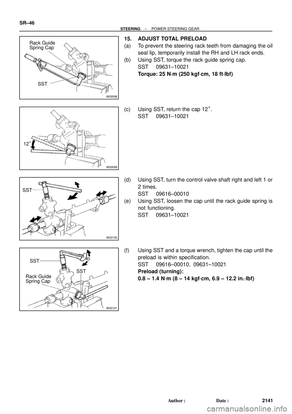
15. ADJUST TOTAL PRELOAD
(a) To prevent the steering rack teeth from damaging the oil
seal lip, temporarily install the RH and LH rack ends.
(b) Using SST, torque the rack guide spring cap.
SST 09631±10021
Torque: 25 N´m (250 kgf´cm, 18 ft´lbf)
(c) Using SST, return the cap 12°.
SST 09631±10021
(d) Using SST, turn the control valve shaft right and left 1 or
2 times.
SST 09616±00010
(e) Using SST, loosen the cap until the rack guide spring is
not functioning.
SST 09631±10021
(f) Using SST and a torque wrench, tighten the cap until the
preload is within specification.
SST 09616±00010, 09631±10021
Preload (turning):
0.8 ± 1.4 N´m (8 ± 14 kgf´cm, 6.9 ± 12.2 in.´lbf)
Page 4343 of 4770
W03084
± SUSPENSION AND AXLETIRE AND WHEEL
SA±3
1954 Author�: Date�:
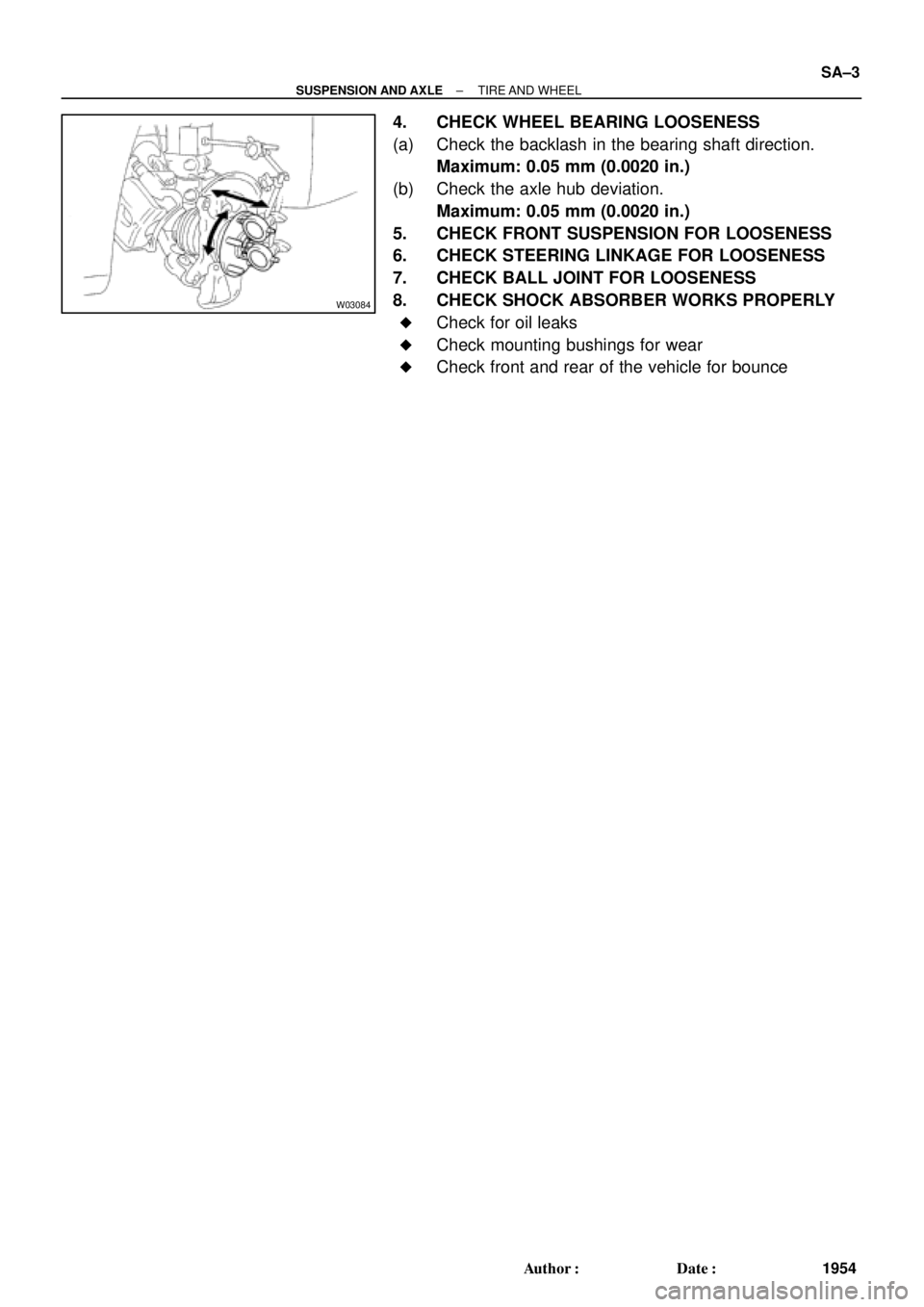
4. CHECK WHEEL BEARING LOOSENESS
(a) Check the backlash in the bearing shaft direction.
Maximum: 0.05 mm (0.0020 in.)
(b) Check the axle hub deviation.
Maximum: 0.05 mm (0.0020 in.)
5. CHECK FRONT SUSPENSION FOR LOOSENESS
6. CHECK STEERING LINKAGE FOR LOOSENESS
7. CHECK BALL JOINT FOR LOOSENESS
8. CHECK SHOCK ABSORBER WORKS PROPERLY
�Check for oil leaks
�Check mounting bushings for wear
�Check front and rear of the vehicle for bounce
Page 4345 of 4770

W03086
F02267
1
2
F01195
Bolt
Adjusting
ValueSet Bolt
15'
30'Adjusting Bolt90105±15001 90105±15004 90105±15005 90105±15006
45'
1°00'
1°15'
1°30'121212121 Dot 2 Dots 3 Dots
± SUSPENSION AND AXLEFRONT WHEEL ALIGNMENT
SA±5
1956 Author�: Date�:
5. ADJUST CAMBER
NOTICE:
After the camber has been adjusted, inspect the toe±in.
(a) Remove the front wheels and speed sensor clamp.
(b) Remove the 2 nuts on the lower side of the shock absorb-
er.
(c) Coat the threads of the nuts with engine oil.
(d) Temporarily install the 2 nuts.
(e) Adjust the camber by pushing or pulling the lower side of
the shock absorber in the direction in which the camber
adjustment is required.
(f) Tighten the nuts.
Torque: 211 N´m (2,150 kgf´cm, 156 ft´lbf)
(g) Install the front wheels.
Torque: 103 N´m (1,050 kgf´cm, 76 ft´lbf)
(h) Check the camber.
HINT:
�Try to adjust the camber to the center value.
�Adjusting value for the set bolts is 6' ± 30' (0.1° ± 0.5°).
If the camber is not within the specification, using the table be-
low, estimate for how much additional camber adjustment will
be required, and select the camber adjusting bolt.
(i) Follow the above mentioned steps again. Between step
(b) and (c), exchange 1 or 2 selected bolts.
HINT:
When exchanging the 2 bolts, exchange 1 bolt for each time.